# Chapter 3. Port Power Requirements
## 3.1. Introduction
Power Requirements define voltages and current ranges that are offered by compliant USB Power Delivery Source Ports and used by compliant USB Power Delivery Sink Ports. Power Requirements enable a collection of interoperable power sources to function with a variety of powered devices in a standard and compliant ecosystem. Power Requirements are generally defined based on a Port's PDP Rating and the Source PDPs (Port Guaranteed PDP, Port Maximum PDP, Port Present PDP) described in Section 6.4.10. The Source Port PDP Rating is the Port Maximum PDP described in Section 6.4.10 and the Sink Port PDP Rating is the maximum PDP the Sink can utilize described in Section 6.5.16. The PDP Rating of a product with multiple Source ports is the highest Port Maximum PDP from the individual Source Ports.
Note: All of the Power Requirements defined in this chapter are for each individual Port.
## 3.2. Source Port Power Requirements
A Source Port is defined as a Guaranteed Capability Port or a Managed Capability Port. For all of the defined requirements, the Capabilities a Source exposes are based on the Port Maximum PDP, or if power constrained, the Port Present PDP.
### 3.2.1. General Source Port Requirements
The following are general Requirements for every Source Port.
1. The Maximum current for a Fixed or Variable PDO is based on the Port Present PDP (x/voltage). The Maximum current **May** be RoundUp or RoundDown to the nearest 10mA.
2. A Source **Shall Not** Advertise a current for a Fixed PDO that would result in the maximum power for that PDO (Voltage × Maximum Current) > maximum power of a higher voltage Fixed PDO.
3. Maximum power for Battery PDOs **Shall** be ≤ PDP Rating and the value can be rounded down.
4. The Maximum current for the SPR Programmable Power Supply (PPS) APDO **Shall** be as defined in Table 3.4.
a. Note: When the PPS Power Limited bit is set in the PPS APDO, the output current is as defined in Table 3.4. However, the Programmable Power Supply **May** limit its output current so that the product of its actual output voltage times the output current does not exceed the Port Present PDP.
b. If a 9V Prog, 15V Prog or 20V Prog Programmable Power Supply APDO is advertised, the maximum current **Shall** be RoundDown (x/Prog Voltage) to the nearest 50mA. When the PPS Power Limited bit is clear, the Source **Shall** provide this current at Maximum Voltage.
5. The first Source Capabilities, when in a Default or Implicit Contract, **Shall** set the Maximum Current of the 5V Fixed PDO ≥ the USB Type-C Current advertised by Rp.
6. The special case of a Source offering no capabilities (0mA or 0W) is described in Section 7.9.1.5.
### 3.2.2. Guaranteed Capability Port
A Guaranteed Capability Port is a Port that, with the exception of a fault condition or a Cable power rating limitation, is always able to provide the Port Maximum PDP. Simple wall chargers, self-powered docks, displays, etc. are typically Guaranteed Capability Ports.
The following Requirements apply to a Guaranteed Capability Port:
1. A Guaranteed Capability Source Port **Shall** set Port Guaranteed PDP = Port Maximum PDP.
2. A Guaranteed Capability Source Port **Shall** set Port Present PDP = Port Maximum PDP except when
a. Port Maximum PDP > 60W and the cable VBUS Current Handling Capability = 3A. In this case, the Port **Shall** set Port Present PDP = 60W.
b. Port Maximum PDP > 100W (EPR Capable) and the Cable is not EPR Capable. In this case, the Port **Shall** set the Port Present PDP ≤ 100W. Note: Margin to 100W (e.g. 95W) is allowed and may be required to comply with safety standards. The actual Port Present PDP is product specific but should be as close to 100W as possible.
### 3.2.3. Managed Capability Port
A Managed Capability Port is a Port that may be constrained such that it does not always provide the Port Maximum PDP. Generally, these types of ports are on products where providing power is not the main function or they are Shared Capacity Ports where power is shared across multiple ports. Portable computers, mobile phones, tablets, shared-capacity docks and displays, etc. are typically Managed Capability Ports.
The following Requirements apply to a Managed Capability Port:
1. A Source **Shall** set Port Guaranteed PDP ≤ Port Maximum PDP.
2. A Source **Shall** set Port Present PDP ≤ Port Maximum PDP.
3. A Source **Shall** provide the PDO/APDOs required for its Port Present PDP as shown in Table 3.2.
4. A Managed Capability Source Port **Shall** limit Port Present PDP when
a. Port Present PDP would be > 60W but the cable VBUS Current Handling Capability = 3A. In this case, the Port **Shall** set Port Present PDP = 60W.
b. Port Present PDP would be > 100W (EPR Capable) and the Cable is not EPR Capable. In this case, the Port **Shall** set the Port Present PDP ≤ 100W.
Note: Margin to 100W is allowed (e.g. 95W) to prevent actual power delivered due to voltage variation to be > 100W. The actual Port Present PDP is product specific but should be as close to 100W as possible.
5. A Source **May** offer Source Capabilities with power less than the Port Present PDP. However, when the Attached Sink has set Mismatch in the Request RDO, the Source **Shall** provide Source Capabilities equivalent to the minimum of either the Source Port Present PDP or the maximum sinking capacity of the Attached Sink found in either Sink Capabilities (PDO) or Extended Sink Capabilities (PDP).
### 3.2.4. Source Voltage and Current Requirements
The following are minimum Requirements for Source Port voltages and currents:
1. The voltages and minimum currents an SPR Source **Shall** support based on the Port Maximum PDP are defined in Table 3.1.
2. The voltages and minimum currents an SPR Source **Shall** support based on the Port Present PDP are defined in Table 3.2.
3. Each SPR PDO and APDO **Shall** only be available if it were required for the Port Maximum PDP as shown in Table 3.1.
Figure 3.1 shows the **Required** voltage and minimum current for each SPR Fixed PDO based on Port Maximum PDP that is described in Table 3.1.
**Figure 3.1. SPR Required Source Power Rule Illustration for Fixed PDOs**
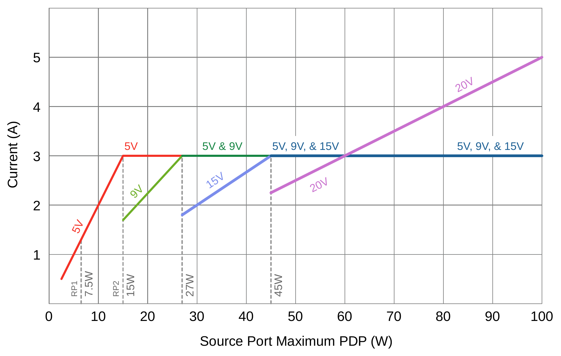
**Table 3.1. SPR Source Voltages and Minimum Currents based on Port Maximum PDP**
| Port Maximum PDP Rating (W) | 5V Fixed (A) | 9V Fixed (A) | 15V Fixed (A) | 20V Fixed (A) | SPR AVS² (A) |
|---|---|---|---|---|---|
| 0.5 ≤ x ≤ 15 | PDP÷5 | - | - | - | - |
| 15 < x ≤ 27 | 3 | PDP÷9 | - | - | - |
| 27 < x ≤ 45 | 3 | 3 | PDP÷15 | - | Max Voltage =15V
Max Current (9-15V) = 15V Fixed PDO Max Current |
| 45 < x ≤ 100 | 3 | 3 | 3 | PDP÷20¹ | Max Voltage = 20V
Max Current (9-15V) = 15V Fixed PDO Max Current
Max Current (15-20V) = 20V Fixed PDO Max Current |
1. Currents > 3A assume the Cable VBUS Current Carrying Capability is capable of the Port Maximum PDP. When it is not, Port Present PDP is limited by the cable. Refer to Table 3.2 for this case.
2. The Sink is allowed to Request up to the 20V Fixed Supply Max Current when the requested voltage from the AVS APDO is 15.0V.
3. '-' indicates PDO or APDO is not allowed.
**Table 3.2. SPR Voltages and Minimum Currents when Port Present PDP < Port Maximum PDP**
| Port Present PDP (W) | 5V Fixed (A) | 9V Fixed (A) | 15V Fixed (A) | 20V Fixed (A) | SPR AVS³,⁴ (A) |
|---|---|---|---|---|---|
| 0.5≤ x ≤ 15 | PDP÷5 | PDP÷9³ | PDP÷15³ | PDP÷20³ | Max Voltage = Max Fixed PDO Voltage¹ |
| 15 < x ≤ 27 | 3 | PDP÷9 | PDP÷15 | PDP÷20 | Max Current (9-15V) = 15V Fixed PDO Max Current
Max Current (15-20V) = 20V Fixed PDO Max Current |
| 27 < x ≤ 45 | 3 | 3 | PDP÷15 | PDP÷20 | Max Current (9-15V) = 15V Fixed PDO Max Current
Max Current (15-20V) = 20V Fixed PDO Max Current |
| 45 < x ≤ 100³ | 3 | 3 | 3 | PDP÷20 | Max Current (9-15V) = 15V Fixed PDO Max Current
Max Current (15-20V) = 20V Fixed PDO Max Current |
1. SPR AVS APDO **Shall** only be available if the 15V Fixed PDO is available.
2. > 60W Port Present PDP requires a 5A cable.
3. This PDO and/or APDO is optional for Port Present PDP ≤ 15W.
4. The Sink is allowed to Request up to the 20V Fixed Supply Max Current when the requested voltage from the AVS APDO is 15.0V
The minimum **Required** Source Capabilities described in Table 3.1 and Table 3.2 can be generalized based on the Port Present PDP by:
- 5V, 9V, and 15V SPR Fixed PDOs
- PDO Maximum Current = Minimum( 3A, Port Present PDP ÷ Fixed PDO Voltage )
- 20V SPR Fixed PDO
- PDO Maximum Current = Minimum( Cable Rating, Port Present PDP ÷ Fixed PDO Voltage )
- SPR AVS
- 9V to 15V maximum current = 15V Fixed PDO Maximum Current
- 15V to 20V maximum Current = 20V Fixed PDO Maximum Current
Table 3.3 shows examples of the SPR Source Capabilities = advertised based on Port Present PDP from Table 3.2.
**Table 3.3. Examples of Required SPR Source Capabilities when Port Present PDP < Port Maximum PDP**
| Port Maximum PDP (W) | Cable Rating (A) | Port Present PDP (W) | Offers: 5V Fixed (A) | Offers: 9V Fixed (A) | Offers: 15V Fixed (A) | Offers: 20V Fixed (A) | Offers: SPR AVS (A) |
|---|---|---|---|---|---|---|---|
| 80 | 5 | 65 | 3 | 3 | 3 | 3.25 | 9V - 15V: 3
15V - 20V: 3.25 |
| 80 | 5 | 40 | 3 | 3 | 2.67 | 2 | 9V - 15V: 2.67
15V - 20V: 2 |
| 80 | 3 | 40 | 3 | 3 | 2.67 | 2 | 9V - 15V: 2.67
15V - 20V: 2 |
| 80 | 5 | 20 | 3 | 2.22 | 1.33 | 1 | 9V - 15V: 1.33
15V - 20V: 1 |
| 80 | 3 | 20 | 3 | 2.22 | 1.33 | 1 | 9V - 15V: 1.33
15V - 20V: 1 |
| 40 | 5 | 20 | 3 | 2.22 | 1.33 | Not offered | 9V - 15V: 1.33 |
| Port Maximum PDP (W) | Cable Rating (A) | Port Present PDP (W) | 5V Fixed (A) | 9V Fixed (A) | 15V Fixed (A) | 20V Fixed (A) | SPR AVS (A) |
| --- | --- | --- | --- | --- | --- | --- | --- |
| 40 | 3 | 20 | 3 | 2.22 | 1.33 | Not offered | 9V - 15V: 1.33 |
| 80 | 3 | 15 | 3 | 1.671 | 11 | 0.751 | 9V - 15V: 11
15V - 20V: 0.752 |
| 40 | 3 | 15 | 3 | 1.671 | 11 | Not offered | 9V - 15V: 11 |
1. This Capability is **Optional** at this Port Present PDP and **May** be offered at this Port Present PDP if the Fixed 15V PDO is offered.
2. This Capability is **Optional** at this Port Present PDP and **May** be offered at this Port Present PDP if the Fixed 20V PDO is offered.
### 3.2.5. Optional Source Voltage/Currents
#### 3.2.5.1. Fixed, Variable and Battery Supply
In addition to the voltages and currents specified in Section 3.2.4, an SPR Source **May** Optionally supply additional voltages and increased currents.
While allowed, the use of **Optional** voltages and currents is strongly discouraged to avoid user confusion. **Optional** voltages or currents allow Sinks that might perform differently with a Source with an **Optional** voltage or current than with a Source with an equivalent Port Maximum PDP but without the **Optional** voltage or current.
The following are Requirements apply to **Optional** Fixed, Variable, and Battery PDOs:
1. A Source **Shall Not** Advertise an optional Fixed PDO voltage > 9V.
2. A Source **Shall** only Advertise a Variable or Battery PDO with a Maximum Voltage ≤ the highest offered Fixed PDO voltage with allowed variance (≤ 1.05 × Fixed PDO Voltage)
3. A Source **Shall Not** Advertise an optional Fixed PDO voltage > the highest **Required** Fixed Voltage PDO in Table 3.1.
4. A Source **May** offer a Variable PDO, a Battery PDO, or a higher Maximum Current in a Fixed PDO than that found in Table 3.1 and Table 3.2. The following Requirements apply:
a. A Source **Shall** not Advertise a Maximum Current for a Fixed PDO > the current defined by the Port Present PDP in Table 3.1 and Table 3.2.
b. A Source **Shall Not** Advertise a Maximum Current for a Fixed PDO that would result in the maximum power for that PDO exceeding the maximum power of the next higher voltage required Fixed PDO (5V, 9V, 15V, or 20V) as specified in Table 3.1 and Table 3.2.
c. A Source **Shall Not** Advertise a Maximum Current for a Variable PDO that would result in the maximum power for that PDO (Maximum Voltage × Maximum Current) exceeding the maximum power (1.05 × Voltage × Maximum Current) of the next higher voltage required Fixed PDO (5V, 9V, 15V, or 20V) as specified in Table 3.1 and Table 3.2. The 1.05 factor accounts for the ±5% voltage tolerance of Fixed PDOs.
d. A Source **Shall Not** Advertise a Maximum Power for a Battery PDO that would result in the maximum power for that PDO exceeding the maximum power (1.05 × Voltage × Maximum Current) of the next higher voltage required Fixed PDO (5V, 9V, 15V, or 20V) as specified in Table 3.1 and Table 3.2. The 1.05 factor accounts for the ±5% voltage tolerance of Fixed PDOs.
5. EPR Capable Sources **Shall Not** implement optional Fixed PDOs.
6. An EPR Capable Source **Shall** only implement a Variable or Battery PDO as an SPR PDO. SPR Variable and Battery PDOs are allowed in EPR Mode.
#### 3.2.5.2. SPR Programmable Power Supply (PPS)
Programmable Power Supply (PPS) is **Optional**. When included, the voltages and currents a PPS **Shall** support are as defined in Table 3.4.
**Table 3.4. SPR PPS APDOs based on the Port Maximum PDP**
| Port Maximum PDP (W) | Prog Voltage = 9V3,4 (A) | Prog Voltage = 15V3,4 (A) | Prog Voltage = 20V3,4 (A) |
| --- | --- | --- | --- |
| x ≤ 15 | - | - | - |
| 15 < x < 27 | PDP÷91 | - | - |
| 27 | 3 | - | - |
| 27 < x < 45 | 32 | PDP÷151 | - |
| 45 | - | 3 | - |
| 45 < x < 60 | - | 32 | PDP÷201 |
| 60 | - | - | 3 |
| 60 < x < 100 | - | - | PDP÷201 |
| 100 | - | - | 5 |
1. The PPS APDOs Maximum Current field **Shall** Advertise RoundDown( PDP ÷ Prog Voltage ) to the nearest 50mA.
2. The PPS APDOs Maximum Current field **Shall** Advertise at least 3A. When the cable VBUS Current Handling Capability = 5A, the Maximum Current field **May** Advertise up to RoundDown( PDP ÷ Prog Voltage ) to the nearest 50mA.
3. See Table 4.2 for the voltage ranges defined for the PPS Prog APDOs.
4. Applies to PPS APDOs regardless of value of the PPS Power Limited bit.
5. '-' indicates APDO is not allowed.
#### 3.2.5.3. Extended Power Range (EPR)
Support of EPR Mode is **Optional**. An EPR Capable Port has a Port Maximum PDP > 100W and ≤ 240W.
Table 3.5 and Table 3.6 define the requirements for EPR Source Ports.
The following Requirements apply to an EPR Capable Source Port (EPR Source Port):
1. An EPR Source Port **May** operate in either SPR Mode or EPR Mode when providing power ≤ 100W.
2. An EPR Source Port **May** be implemented as a Managed Capability Port or Guaranteed Capability Port.
3. An EPR Source Port, operating in SPR Mode, **May** Advertise the SPR 20V Fixed PDO with < 5A (< 100W) to avoid potentially violating external safety regulations. This value should be as close as possible to 100W if not otherwise limited by Port Present PDP.
4. When operating in EPR Mode, an EPR Source Port with a Port Present PDP ≥ 100W **Shall** offer 5A in the 20V Fixed PDO.
5. When the Attached cable is not an EPR Capable cable, an EPR Capable Source **Shall** only operate in SPR Mode.
6. When in EPR Mode, an EPR Source Port that supports PPS **Shall** offer the SPR Fixed 20V PDO and PPS 20V Prog APDO at the Port Present PDP, up to 100W.
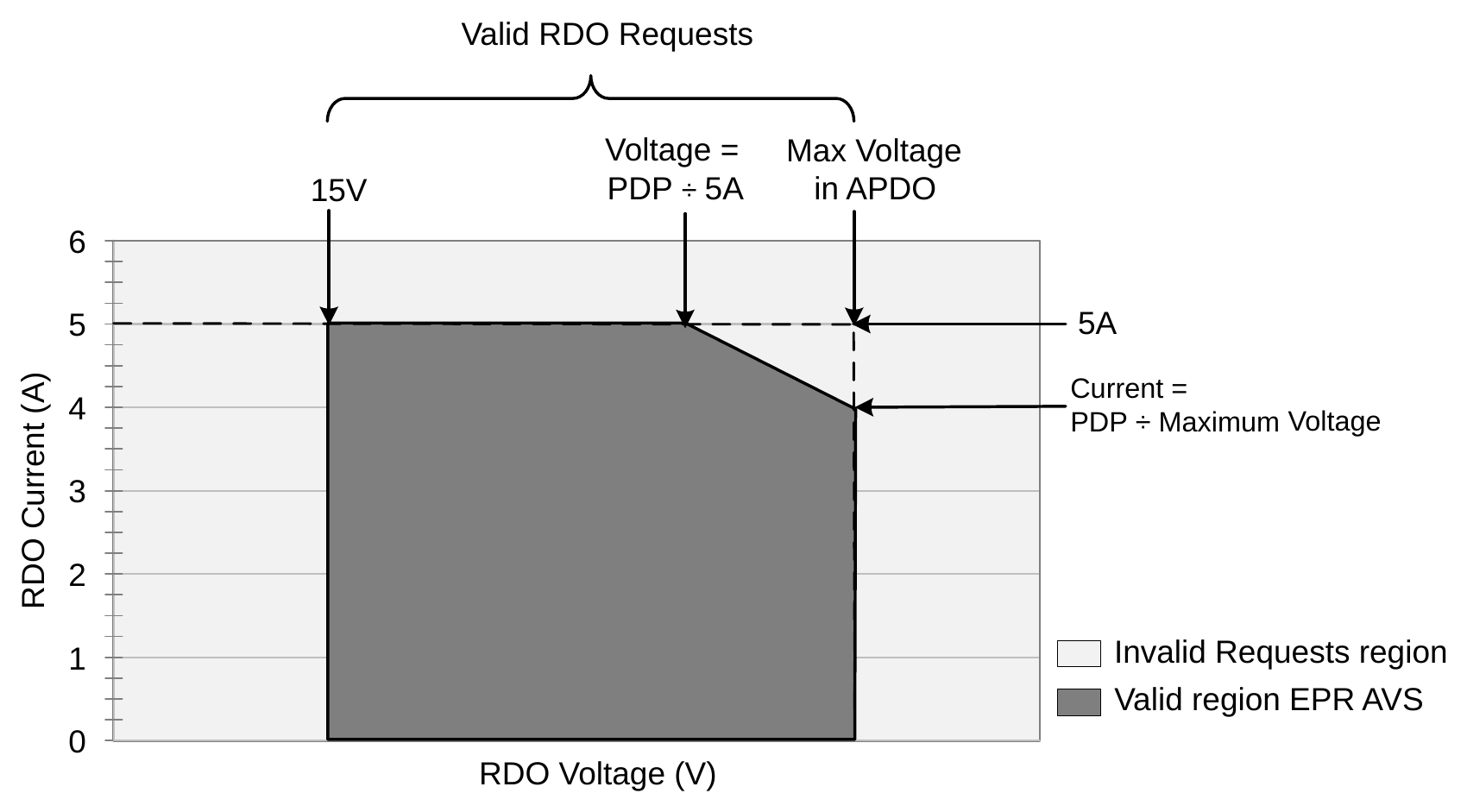
7. An EPR Source Port in an EPR AVS Contract **Shall** stay within the power offered in the PDP Field from the EPR AVS APDO defined in Table 6.16 and **Shall** Reject any Request whose operating current exceeds (PDP ÷ requested voltage) or 5A.
Figure 3.3 shows the definition of the valid operating range for an EPR Source operating in an AVS Explicit Contract based on the PDP Field.
Figure 3.2 combined with Figure 3.1 shows the minimum current that an EPR Source **Shall** support at each EPR Fixed PDO for a given Port Maximum PDP.
**Figure 3.2. EPR Source Power Rule Illustration for Fixed PDOs**
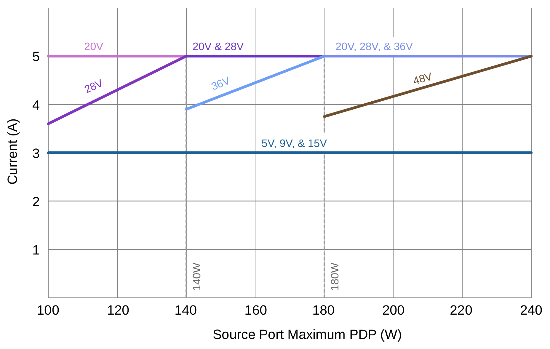
**Table 3.5. EPR Source Capabilities based on the Port Maximum PDP**
| Port Maximum PDP (W) | 28V Fixed (A) | 36V Fixed (A) | 48V Fixed (A) | EPR AVS2 (A) |
| --- | --- | --- | --- | --- |
| 100 < x ≤ 140 | PDP÷28 | - | - | Max Voltage = 28V
Available Current (15-28V) = PDP ÷ AVS voltage (maximum of 5A) |
| 140 < x ≤ 180 | 5 | PDP÷36 | - | Max Voltage = 36V
Available Current (15-36V) = PDP ÷ AVS voltage (maximum of 5A) |
| 180 < x ≤ 240 | 5 | 5 | PDP÷48 | Max Voltage = 48V
Available Current (15-48V) = PDP ÷ AVS voltage (maximum of 5A) |
1. '-' indicates PDO or APDO is not allowed.
2. The current available for a given AVS voltage is as indicated in this column. The current defined here is describing the top edge of the **Valid** Operating Region as illustrated in Figure 3.3. The AVS APDO does not have a Maximum Current field, so the maximum current is calculated from the Port Present PDP.
**Table 3.6. EPR Source Capabilities when Port Present PDP < Port Maximum PDP**
| Port Present PDP (W) | 28V Fixed1 (A) | 36V Fixed1 (A) | 48V Fixed1 (A) | EPR AVS (A) |
| --- | --- | --- | --- | --- |
| 7.5 < x ≤ 27 | PDP÷282 | PDP÷362 | PDP÷482 | Max Voltage = Max Fixed PDO Voltage3
Available Current = PDP ÷ AVS Voltage (maximum of 5A) |
| 27 < x ≤ 45 | PDP÷28 | PDP÷362 | PDP÷482 | Max Voltage = Max Fixed PDO Voltage3
Available Current = PDP ÷ AVS Voltage (maximum of 5A) |
| 45 < x ≤ 60 | PDP÷28 | PDP÷36 | PDP÷482 | Max Voltage = Max Fixed PDO Voltage3
Available Current = PDP ÷ AVS Voltage (maximum of 5A) |
| 60 < x ≤ 75 | PDP÷28 | PDP÷36 | PDP÷48 | Max Voltage = Max Fixed PDO Voltage3
Available Current = PDP ÷ AVS Voltage (maximum of 5A) |
| 75 < x ≤ 100 | PDP÷28 | PDP÷36 | PDP÷48 | Max Voltage = Max Fixed PDO Voltage3
Available Current = PDP ÷ AVS Voltage (maximum of 5A) |
| 100 < x ≤ 140 | PDP÷28 | PDP÷36 | PDP÷48 | Max Voltage = Max Fixed PDO Voltage3
Available Current = PDP ÷ AVS Voltage (maximum of 5A) |
| 140 < x ≤ 180 | 5 | PDP÷36 | PDP÷48 | Max Voltage = Max Fixed PDO Voltage3
Available Current = PDP ÷ AVS Voltage (maximum of 5A) |
| 180 < x ≤ 240 | 5 | 5 | PDP÷48 | Max Voltage = Max Fixed PDO Voltage3
Available Current = PDP ÷ AVS Voltage (maximum of 5A) |
1. Each EPR Fixed PDO is only available if it were required for the Port Maximum PDP as shown in Table 3.5.
2. This PDO is **Optional** for this Port Present PDP.
3. This APDO is **Required** when an EPR Fixed PDO is offered.
EPR Source Capabilities described in Table 3.5 and Table 3.6 can be generalized based on the Port Present PDP by:
- For each Fixed PDO
- PDO Maximum Current = Minimum( 5A, PDP ÷ Fixed PDO Voltage )
- 48V Fixed PDO is not allowed if Port Maximum PDP ≤ 180W and otherwise optional if Port Present PDP ≤ 60W.
- 36V Fixed PDO is not allowed if Port Maximum PDP ≤ 140W and otherwise optional if Port Present PDP ≤ 45W.
- 28V Fixed PDO is optional if Port Present PDP ≤ 27W.
- EPR AVS
- PDO Maximum Voltage = Maximum offered Fixed PDO Voltage
- PDO Minimum Voltage = 15V
- PDO PDP = Port Present PDP
Table 3.7 shows examples of the SPR Source Capabilities = advertised based on Port Present PDP from Table 3.2.
**Table 3.7. Examples of EPR Source Capabilities when Port Present PDP 1 | 0.751 | 48V@36W1 |
| 160 | 36 | 1.29 | 11 | Not offered | 36V@36W1 |
| Port Maximum PDP (W) | Port Present PDP (W) | Offers | | | |
| --- | --- | --- | --- | --- | --- |
| | | 28V Fixed(A) | 36V Fixed(A) | 48V Fixed(A) | EPR AVS max Voltage (V) and Power (W) |
| 120 | 36 | 1.29 | Not offered | Not offered | 28V@36W |
1. These Capabilities are not required but may be offered at this Port Present PDP.
**Figure 3.3. Valid EPR AVS Operating Region**
## 3.3. Dynamic Power Supply (DPS)
The Source power Requirements defined in Section 3.2.4 and Section 3.2.5 **Shall** apply to a DPS Port, together with the following additional Requirements:
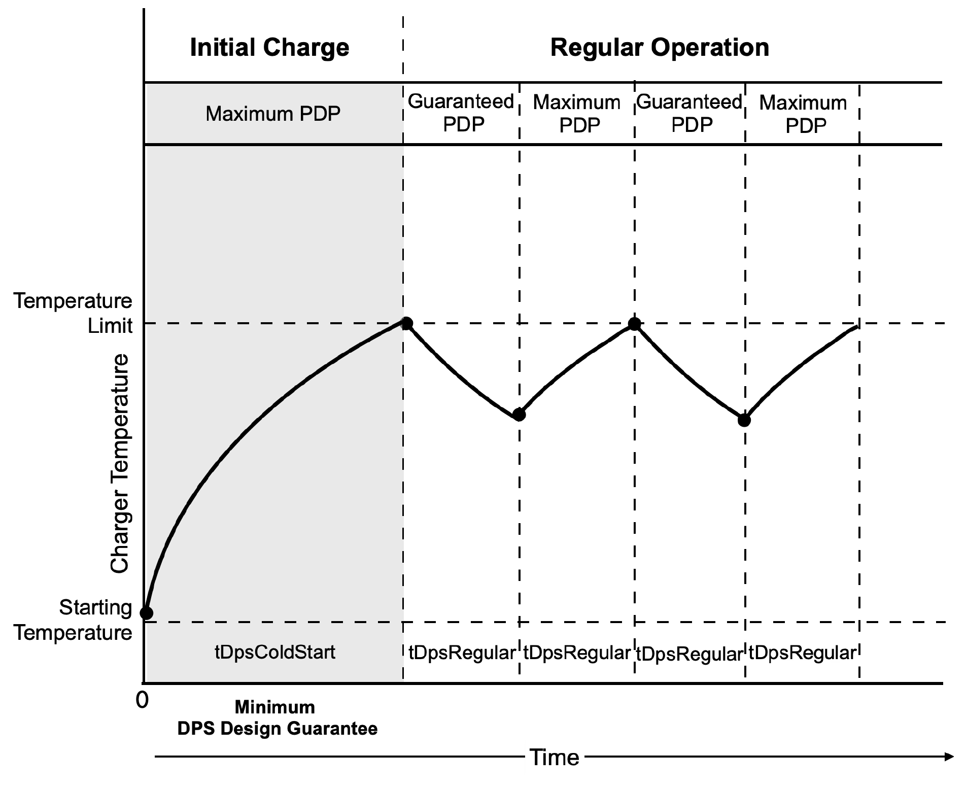
1. A DPS Port **Shall** guarantee tDpsColdStart at Maximum PDP provided the following conditions are met:
a. The unit is starting from a cold start. This means the components inside the unit are at ambient temperature, and the ambient temperature **Should** be around 25°C.
b. The Source Port is not sourced by an internal Battery, per the Source Inputs Field of the Source Capabilities Extended Message.
c. No other events arise that may require the Source to send New Source Capabilities (e.g. a new Request from the Sink).
2. The Source **Should** not send updated Source Capabilities within tDpsRegular or tDpsColdStart, with the following exceptions:
a. If the Source just entered its First Explicit Contract with the Sink, it **May** send an updated Source Capabilities Message, provided the Sink sets the Capability Mismatch bit, and the Source can increase the power offered.
b. The updated Source Capabilities are due to sharing power with another Port when the Source is a shared capability Port.
c. Events arise that may require the Source to send New Source Capabilities (e.g. a new Request from the Sink).
d. Parameters other than the temperature affect the Source Capabilities.
**Figure 3.4. Example of a DPS temperature profile**
A DPS Source uses Alert Message, Status Message, and Source Info Message fields to inform a Sink about changes in its Capabilities. See Section 7.14 and Section 7.26 for additional details on requirements for these fields.
## 3.4. Sink Power Requirements
### 3.4.1. Sink Power Rule Considerations
The Sink Power Requirements are designed to ensure the best possible user experience when a given Sink is powered by a compliant Source that only supplies the **Required** voltages and currents.
Sinks are designed to use Sources with a matching or higher PDP Rating. The Sink Power Requirements are based on the following considerations:
- Low power Sources (e.g., 5V) are expected to be very common and will be used with Sinks designed for a higher PDP.
- Optimizing the user experience when Sources with a higher PDP Rating are used with low power Sinks.
- Preventing Sinks that only function well (or at all) when using **Optional** voltages and currents.
### 3.4.2. Sink Requirements
The following Requirements apply to Sink RDO:
1. A Sink **Shall** set RDO Operational Current or RDO Maximum Power to result in power ≤ Sink Maximum PDP.
2. A Sink **Should** set Capabilities Mismatch when the voltage, current, or power being offered in Source Capabilities is insufficient for optimal operation or charging. A Sink **Shall** not set Capabilities Mismatch otherwise.
3. A Sink **Shall** set RDO Operational Current or Maximum Current as RoundDown to the nearest 10mA for Fixed/Variable/AVS PDO/APDO Supplies and 50mA for PPS APDO.
4. A Sink without a Battery **Shall** set Maximum Power for a Battery Supply RDO to ≤ Sink Operational PDP.
5. A Sink requiring no power from the Source, **Shall** send the 5V RDO with Operational Current set to 0mA.
The following Requirements apply to Sink Capabilities:
1. A Sink **Shall Not** Advertise Fixed PDO maximum voltages and currents that exceed the Sink_Capabilities_Extended Message SPR Sink Maximum PDP when in SPR Mode and EPR Sink Maximum PDP when in EPR Mode.
2. A Sink **Shall Not** Advertise Variable PDO maximum voltages and currents that exceed the Sink_Capabilities_Extended Message SPR Sink Maximum PDP when in SPR Mode and EPR Sink Maximum PDP when in EPR Mode.
3. A Sink **Shall Not** Advertise a Battery PDO maximum allowable power that exceeds the Sink_Capabilities_Extended Message SPR Sink Maximum PDP when in SPR Mode and EPR Sink Maximum PDP when in EPR Mode.
4. A Sink **Shall Not** Advertise a PPS APDO maximum allowable power that exceeds the Sink_Capabilities_Extended Message SPR Sink Maximum PDP when in SPR Mode and EPR Sink Maximum PDP when in EPR Mode.
5. A Sink **Shall Not** Advertise an AVS APDO maximum allowable power that exceeds the Sink_Capabilities_Extended Message SPR Sink Maximum PDP when in SPR Mode and EPR Sink Maximum PDP when in EPR Mode.
## 3.5. Sink with Acessory Support
The following Requirement applies to a Sink with Accessory Support:
1. When sourcing VCONN, a Sink with Accessory Support is considered a Source even though VBUS is not supplied. The Sink with Accessory Support **Shall** offer a single 5V PDO with the Maximum Current field set to 0mA for the purpose of allowing a VPA to enter an Alternate Mode.
## 3.6. PDUSB Device Requirements
A PDUSB Device **Shall** comply with the requirements defined in [PDUSB].