12 KiB
Chapter 1. Introduction
USB Power Delivery (PD) is a power transfer standard that allows USB cables and connectors to deliver higher power levels (up to 240W) for a wide range of devices, including laptops, tablets, smartphones, and peripherals. In addition to power delivery, USB PD supports data protocol negotiations over USB-C, thus making it a versatile solution for both power and data configurations.
Key features of USB PD:
- Negotiable power output – Supports negotiating power up to 240W (48V/5A) to power high-demand devices like laptops, monitors, and gaming consoles.
- Renegotiable power – Powered devices and power sources renegotiate power levels to deliver optimal power based on a particular Device's immediate requirements.
- Bidirectional power – Devices can both provide and consume power, enabling features like Host charging (e.g., powering a laptop from an external monitor).
- Unified connector – Uses the USB-C connector that supports both power and data transfer through a single cable.
- Data protocol Negotiation – USB PD allows a Device to Connect using the default USB2/USB3 data connection or switch to alternate data modes, enabling USB-C to support additional protocols such as DisplayPort, USB4, and Thunderbolt 3 for video output and high-speed data transfer.
In summary, USB PD maximizes the potential of USB-C by providing both flexible power delivery and data protocol negotiations, thus making it a universal solution for modern devices.
1.1. Cable and Connectors
The USB Power Delivery specification assumes the use of certified USB cables and associated detection mechanisms as defined in [USB-C].
1.2. Operational Overview
A USB PD connection is based on the underlying USB-C standard and roles as defined in [USB-C]. The Source Port provides power, and the Sink Port consumes power. Each connection has one Source and one Sink, which are established during the initial connection.
At the point of Attachment, the Source Port functions as both the Downstream Facing Port (DFP) and the VCONN Source, while the Sink Port functions as the Upstream Facing Port (UFP).
Power roles (Source/Sink), data roles (DFP/UFP), and the VCONN Source role can be swapped independently during a connection. These role swaps depend on whether the ports support Dual-Role Power (DRP) or Dual-Role Data (DRD) Capabilities. Ports with dual-role Capabilities can switch between providing and consuming power or acting as the data Host or Device, depending on the Negotiation.
1.3. USB PD Roles
1.3.1. Source Port
The Source Port is typically associated with devices like chargers, power banks, notebooks, and docks that power other devices and provide the power in a USB PD connection. The Source defaults to being the DFP at initial connection. It supplies power to a Connected Sink Port and is responsible for initiating power negotiations to determine the appropriate voltage and current levels needed by the connection.
1.3.2. Sink Port
The Sink Port is the power-consuming Port in a USB PD connection and is typically associated with devices like smartphones, tablets, notebooks, and peripherals that rely on an external power Source to charge. The Sink defaults to being the UFP at initial connection. It draws power from a Connected Source Port and participates in power Negotiation to ensure it receives the appropriate voltage and current levels.
1.3.3. Downstream Facing Port (DFP)
The Downstream Facing Port (DFP) is the Port in a USB-C connection associated with the USB Host role. It is the Initiator in Data Role negotiations and handles most downstream data communications. See [USB2] and [USB3] for more information about Downstream ports.
1.3.4. Upstream Facing Port (UFP)
The Upstream Facing Port (UFP) is the Port in a USB-C connection that is associated with the USB Peripheral role. It is the Responder in Data Role Negotiation and handles most upstream data communication. See [USB2] and [USB3] for more information about Upstream ports.
1.3.5. Dual-Role Power (DRP) Ports
Dual-Role Power Ports can operate as either a Source or a Sink and swap between the two Power Roles as needed.
1.3.6. Dual-Role Data (DRD) Ports
Dual-Role Data Ports have the ability to operate as either a DFP or a UFP and to swap between the two Data Roles. Products can be Dual-Role Data Ports without being Dual-Role Power Ports. This means that they can switch logically between DFP and UFP Data Roles, even if they are Source-only or Sink-only for power.
1.3.7. VCONN Source
The VCONN Source is the Port that provides power to Cable Plugs. The VCONN Source is typically the Downstream Facing Port (DFP) and supplies power to enable Active Cable circuitry and support cable identification and management in USB PD connections. To commuunicate with Cable Plugs, a Port must be the VCONN Source. For more information about a USB Type-C Source Port's requirements regarding VCONN, see [USB-C].
1.3.8. Cable Plugs
In the context of USB PD, Cable Plug refers to embedded USB PD communication-capable circuitry within a cable, plug, or accessory that is typically associated with a single plug end of a cable or a captive plug on a Device. This circuitry consists of the embedded electronic marker (e-marker) chip and/or any active circuitry within the Cable.
Cable Plugs are powered when VCONN is present but are generally not aware of the status of the Contract between the two Connected ports. They do not initiate communication and only respond to messages that are addressed to them.
The Source or Sink communicates with the Cable Plug circuitry to retrieve information about the Attached cable or accessory, such as current-carrying capability or supported data rates, or to direct the plug to enter a specific data Mode.
1.4. Power Delivery Operational Contracts
A PD Source and Sink will be in one of three Contracts:
- Default Contract – A non-Negotiated power Contract established at the initial connection, as defined in [USBC], withadefault voltageof5V. The Sink mightdraw uptotheadvertised USB-C current. The Sourceremains in the Default Contract until the Sink disconnects or both ports Negotiate and establish an Explicit Contract.
- Explicit Contract – The State of the Source and Sink after any PD Power Negotiation has taken place. This is the normal operational State for PD and must be entered before other USB PD messaging can occur. A Source offers power contracts to a Sink using USB PD messaging, and the Sink requests a Contract, which is then accepted by the Source. Data connections and modes other than USB2 and USB3 might be established in an Explicit Contract.
- Implicit Contract – A transitory power Contract that follows a Power Role Swap or Fast Role Swap. The available voltage, similar to a Default Contract, is 5V, with current defined by the advertised USB-C current. The Source in an Implicit Contract will immediately Negotiate with the Sink to establish an Explicit Contract. All data connections and modes are maintained during an Implicit Contract.
1.5. Source and Sink Operation in USB PD
In a USB PD connection, the Source and Sink engage in a series of Message exchanges to Negotiate power contracts, data roles, and Mode implementation (such as Alternate Mode or USB4 Mode). This process ensures both ports operate with compatible power levels and functional Capabilities.
1.5.1. General Source-to-Sink Initial Interaction
-
Initial Connection (Attach) – Defined by [USB-C].
- The Source asserts Rp (pull-up resistor or pull-up current) on the CC line, and the Sink asserts Rd (pulldown resistor) to establish the connection.
- The Source provides a Default Contract at the advertised Rp current at 5V upon connection.
-
Power Discovery.
- The Source advertises its available power options through its Source Capabilities. These messages define voltage (e.g., 5V, 9V, 15V, 20V) and current levels the Source can supply.
-
Power Negotiation and Explicit Contract. The Sink requests the preferred power option based on its requirements.
- The Source accepts the Request to establish the Explicit Contract.
- The Source then indicates that it is supplying the agreed power level.
- Once the Explicit Contract is established, both ports enter a stable power State and might establish a Data Role change or Mode Entry.
-
Data Role and Mode Entry.
- When a role change is desired, the Source and Sink exchange Data Role messages to determine the DFP (Downstream Facing Port) and UFP (Upstream Facing Port) roles.
- The Source might Request the Sink to send capability information and to confirm data Mode compatibility.
- The Source might initiate USB4 Mode Entry, if supported.
- The Source can initiate Alternate Mode Entry by asking the Sink to Advertise its supported modes.
- If a compatible Alternate Mode is found (e.g., DisplayPort), the Source requests to enter the Mode.
-
Ongoing Communication and Role Swaps
- During the connection, the Source and Sink can continue to exchange Control and Data messages to renegotiate power levels, switch roles, etc.
- Both ports can perform a Power Role Swap, where the Source becomes the Sink, and vice versa.
- A Data Role Swap can also occur, changing which Port acts as the DFP (Host) or UFP (Peripheral) for data transfer.
1.6. Common PD Device Types
USB PD devices fall into a few general categories, such as:
- Dedicated power sources – wall chargers (bricks), power banks, etc.
- Host systems – computers (desktop, portable), mobile phones, tablets, etc.
- Peripherals – mice, keyboards, displays, hard drives, cameras, speakers, headsets, etc.
- Data routers – hubs, docks.
Some devices can be combinations such as a display/dock or cameras that can function as a Host or Device. With USB PD, these can also be power Sources or power Sinks, or both, depending on what they are Attached to. For example, a Host computer can be a power Sink and be charged when Connected to a wall Charger, but it might then be a power Source to a downstream Peripheral such as a hard drive.
1.7. USB-PD Architectural Overview
This section describes the logical architecture of the USB Power Delivery (USB PD) specification. The architecture overview presented here is conceptual and not intended to prescribe a specific implementation. Rather, it provides a high-level framework that is referenced throughout this specification.
USB PD defines a bus protocol specifying voltage levels, current limits, Signaling, timing, and other interface parameters that are Negotiated between two ports. It does not define how these requirements must be implemented in a particular Device. Implementation details are left to the product designer and are outside the scope of this specification.
At a high level, USB PD is structured as a hierarchy of control layers, where each layer communicates with its adjacent layers. From lowest to highest, these layers are:
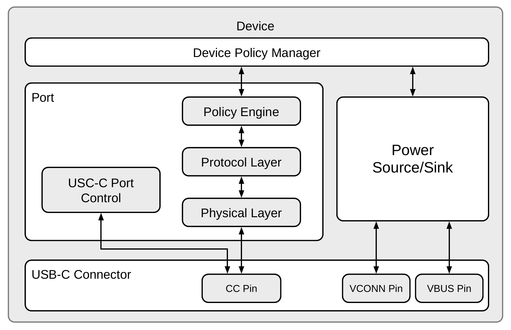
Device Policy Manager: Coordinates USB PD behavior across the Device by managing one or more ports based on the Device's overall power and data Policy.Policy Engine: Enforces local power and data Policy for an individual Port.Protocol Layer: Constructs and interprets USB PD messages exchanged between ports.Physical Layer: Handles bit-level transmission and reception on the physical connector and performs error detection on messages using a CRC mechanism.USB-C Port Control: Provides mechanisms to execute USB-C State machines and informing the other layers of Attach/Detach events, plug orientation, and set and detect Type-C current advertisements.
Each Port includes its own USB-C Port Control, Physical Layer, Protocol Layer, and Policy Engine. The Device Policy Manager is a single entity that manages all ports within the Device.
USB PD operates over a USB-C connector; as such, the State machines defined in [USB-C] reside within or closely interact with the USB PD control layers. Similarly, voltage and current control for power delivery interface tightly with these layers. Figure 1.1 illustrates these architectural elements.
Figure 1.1. USB PD Capable Device High Level Architecture