
161 KiB
Chapter 6. PD Communications Protocol Message Definitions
6.1. Overview
This chapter defines the different types of PD Messages and provides details on how they are constructed.
Refer to Chapter 7 for details on Message usage.
6.1.1. Message Types
This specification defines three types of Messages:
- Control Messages that contain the 16-bit Message Header.
- Data Messages that contain a 16-bit Message Header, followed by between one and seven 32-bit data objects.
- Extended Messages that contain the 16-bit Message Header, followed by the 16-bit Extended Message Header and between 1 and 260 bytes of data.
Note: Data messages are word-oriented while extended messages are byte-oriented.
6.1.2. Message ID
All messages are sent with a Message Header that contains the 3-bit MessageID field. The MessageID is a 3-bit counter that is used to ensure duplicate messages are handled properly. Ports **Shall** keep a different MessageID counter for each supported SOP*.
Instead of using the MessageID counter, the MessageID field for GoodCRC Message **Shall** match the MessageID field of the received Message that the GoodCRC Message is acknowledging.
6.1.3. Specification Revision
To ensure interoperability with existing PDUSB products, all PDUSB products **Shall** support every PD Specification Revision starting from [PD2] for SOP*; the only exception to this is a VPD which **Shall** ignore Messages sent with PD Specification Revision 2.0 and earlier. In order to facilitate compatibility, the Message Header of all messages contains a field describing the Revision of the USBPD Specification it supports.
After an Attach, a Port discovers the lowest common Specification Revision level between itself and its Port Partner and/or the Cable Plug(s), and **Shall** use this Specification Revision level until a Detach, Hard Reset, or Error Recovery occurs.
After determining the Specification Revision to be used, all PD communications **Shall** comply completely with the relevant Revision of the PD specification.
The 2-bit Specification Revision field of a GoodCRC Message does not carry any meaning. The value received could be 00b, 01b, 10b, or 11b and **Shall** be ignored by the recipient of the Message. The sender of a GoodCRC Message **Shall** set the Specification Revision field to 01b (Revision 2.0) when responding to a Message that contains 01b in the Specification Revision field of the Message Header. The sender of a GoodCRC Message May set the Specification Revision field to 01b or 10b when responding to a Message that contains 10b (Revision 3.x) in the Specification Revision field of the Message Header.
All data in all Messages **Shall** be consistent with the definition from the USB-PD spec Version indicated in the Specification Revision field in the Message Header for that particular Message.
6.1.3.1. SOP Specification Revision Detection Process
An Attach event (or a Hard Reset) **Shall** cause the detection of the applicable Specification Revision to be implemented for Ports according to the rules stated below:
- The Source Port sends a Source_Capabilities Message to the Sink Port setting the Specification Revision field to the highest Revision of the Power Delivery Specification the Source Port supports.
- The Sink Port responds with a Request Message that sets the Specification Revision field to the highest Revision of the Power Delivery Specification the Sink Port supports that is equal to or lower than the Specification Revision received from the Source Port.
- The Source and Sink Ports
**Shall**use the Specification Revision in the Request Message from the Sink in step 2 in all subsequent communications until a Detach, Hard Reset, or Error Recovery occurs.
6.1.3.2. SOP' Specification Revision Detection Process
After Attach, and prior to a VCONN Swap, the initial VCONN Source **Shall** use the following steps to establish a Specification Revision level for Cable Plugs according to the rules stated below:
- The VCONN Source sends a Discover Identity REQ to the Cable Plug (SOP') that sets the Specification Revision field in the Message to the highest Revision of the Power Delivery Specification the VCONN Source supports.
- The Cable Plug responds with a Discover Identity ACK that sets the Specification Revision field in the Message to the highest Revision of the Power Delivery Specification it supports that is equal to or lower than the Specification Revision it received from the Source Port.
- The Cable Plug and VCONN Source
**Shall**communicate using the lower of the two revisions until an Explicit Contract has been established. - Table 6.1 shows the Specification Revision that
**Shall**be used between the Port Partners and the Cable Plugs when the Specification Revision has been discovered and an Explicit Contract is in place.
After a VCONN Swap, the new VCONN Source, that intends to communicate directly with the Cable Plug(s), **Shall** use the following steps to establish a Specification Revision level:
- The new VCONN Source sends the required Soft_Reset Message to synchronize its SOP' State machine with the Cable Plug, setting the Specification Revision field in the Message Header to the highest Revision of the Power Delivery specification it supports.
- The Cable Plug responds with an Accept Message, setting the Specification Revision field in the Message to the highest Revision of the Power Delivery Specification it supports that is equal to or lower than the Specification Revision it received from the Source Port.
Notes:
- A VCONN Source that does not communicate directly with the Cable Plug(s) may skip the above procedure.
- When a Cable Plug does not respond to a Revision 3.x Discover Identity REQ with a Discover Identity ACK or BUSY, the VCONN Source may repeat steps 1–4 using a Revision 2.0 Discover Identity REQ in step 1 before establishing that there is no Cable Plug to communicate with.
- This process is closely linked to PD Capability discovery as described in Section 8.6.1.2.1.
A VCONN Source that supports Revision 3.x of the Power Delivery Specification May communicate with a Cable Plug also supporting Revision 3.x using Revision 3.x Compliant Communications regardless of the Specification Revision of its Port Partner while no Explicit Contract exists. After an Explicit Contract has been established the Port Partners and Cable Plug(s) **Shall** use Table 6.1 to determine the Revision to be used.
A Cable Plug **Shall Not** save the State of the agreed Specification Revision. A Cable Plug **Shall** respond with the highest Specification Revision it supports that is equal to or lower than the Specification Revision contained in the Message received from the VCONN Source.
Cable Plugs **Shall** operate using the same Specification Revision for both SOP' and SOP''. Cable assemblies with two Cable Plugs **Shall** operate using the same Specification Revision for both Cable Plugs.
See Table 6.1 for details of how various Revisions **Shall** inter-operate.
Table 6.1. Revision Interoperability during an Explicit Contract
| Port 1 Revision | Cable Plug Revision | Port 2 Revision | Port to Port Operating Revision | Port to Cable Plug Operating Revision |
|---|---|---|---|---|
| 2 | 2 | 2 | 2 | 2 |
| 2 | 2 | 3 | 2 | 2 |
| 2 | 3 | 2 | 2 | 2 |
| 2 | 3 | 3 | 2 | 2 |
| 3 | 2 | 2 | 2 | 2 |
| 3 | 2 | 3 | 3 | 2 |
| 3 | 3 | 2 | 2 | 2 |
| 3 | 3 | 3 | 3 | 3 |
6.1.4. Chunking
With USBPD Revision 2, the longest PD Message that can be transferred is 7 data objects, totaling 28 bytes.
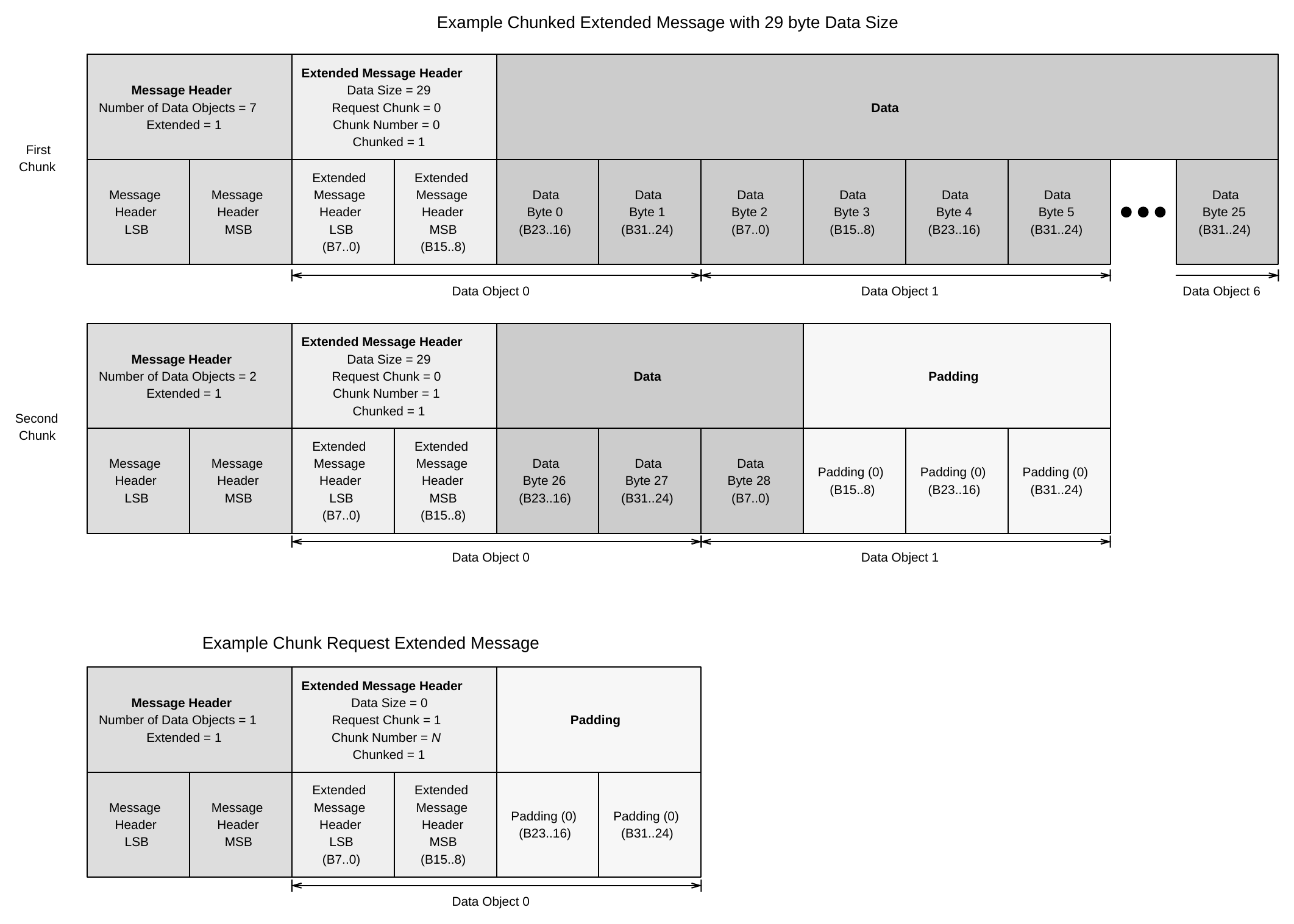
The Extended Message Type was introduced in USBPD Revision 3.0 V1.0, and may transfer up to 260 bytes per Message. Since Extended Messages may be longer than Data Messages, Chunking allows USBPD devices with older PHY hardware to send and receive Extended Messages. Chunking splits an Extended Message into "chunks" that can be sent and received similarly to Data Messages. Each Chunk is no longer than MaxExtendedMsgChunkLen bytes long. See Section 6.5.1.1.
Figure 6.1. Construction of Chunked Extended and Chunk Request Messages
6.1.5. Vendor and Product IDs
Vendor IDs (VID) and Product IDs (PID) are 16-bit values used by USBPD to identify an individual Device. Vendor IDs are assigned by USB-IF and Product IDs are assigned by the Vendor.
Multiple Messages contain VID/PID fields that may either describe the Device Port itself, or a Battery Attached to the Device. USBPD Messages describing the VID/PID associated with the Device Port **Shall** all respond with the same values. Messages that describe VID/PID include:
- Discover Identity Message Response.
- Source_Capabilities_Extended Message.
- Sink_Capabilities_Extended Message.
- Manufacturer_Info Message.
For USB Devices or Hubs which support USB Communications, the USB Vendor ID field **Shall** be identical to the Vendor ID field defined in the product's USB Device Descriptor (see [USB2] and [USB3]).
If the vendor does not have a VID, VID fields in Messages **Shall** be set to FFFFh. If the VID field is FFFFh, a PID field in the same Message **Shall** be set to 0000h.
Vendor Defined Messages contain an SVID field that is similar to VID. However, the SVID field is used to describe the contents of the Vendor Defined Message and may not match the VID of the Device Port that is transmitting the Message.
6.2. Message Construction
All Messages **Shall** begin with a Message Header and May be followed by a variable length (including zero) data portion. The following figure illustrates the three different messages types as they exist inside a PD Packet.
Figure 6.2. Format of PD Packets for Different Message Types
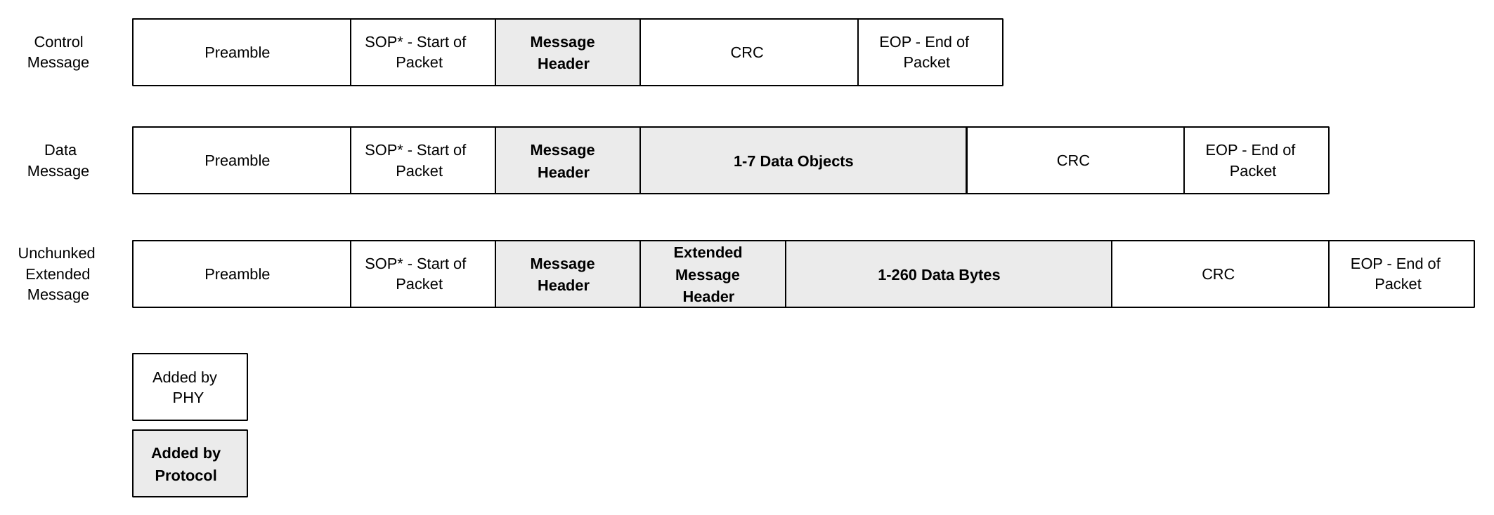
The 16-bit Message Header, 16-bit Extended Message Header, and all 32-bit Data Objects are transmitted least-significant byte first.
6.2.1. Message Header
Each PD Message starts with a 16-bit Message Header as defined in Table 6.2.
Table 6.2. Message Header
| Bit(s) | Field Name | Applicable SOP | Description |
|---|---|---|---|
| 15 | Extended | All | 0 - Indicates a Control or Data Message 1 - Indicates an Extended Message. |
| 14...12 | Number of Data Objects | All | See Section 6.2.2. |
| 11...9 | MessageID | All | Value generated by a rolling counter maintained by the originator of the Message. |
| 8 | Port Power Role | SOP | Present Power Role of the Port that is sending this Message: 0 - Sink 1 - Source Shall Not be verified by the receiver and therefore Shall Not lead to Soft Reset, Hard Reset or Error Recovery if it is incorrect. At Attachment or Hard Reset, this field is set to 0 for the Port presenting Rd and set to 1 for the Port presenting Rp. |
| 8 | Cable Plug | SOP'/SOP'' | Indicates Message sender type: 0 - Port (DFP/UFP) 1 - Cable Plug or VPD |
| 7...6 | Specification Revision | All | 00b - Revision 1.0 (Deprecated, receiver Shall interpret as Revision 2.0).01b - Revision 2.010b - Revision 3.x11b - Reserved. |
| 5 | Port Data Role | SOP | Present Data Role of the Port that is sending this Message: 0 - UFP 1 - DFP At Attachment or Hard Reset, this field is set to 0 for the Port presenting Rd and set to 1 for the Port presenting Rp. If a USB Type-C Port receives a Message with the Port Data Role field set to the same Data Role as its current Data Role, except for the GoodCRC Message, USB Type-C Error Recovery actions as defined in [USB-C] Shall be performed. |
| 5 | Reserved | SOP'/SOP'' | Reserved, receiver ignores this field. |
| 4...0 | Message Type | All | Indicates type of Message being sent. To determine the exact Message type: • If Extended is set, refer to Section 6.5. • Otherwise, if Number of Data Objects is greater than 0, refer to Table 6.5. • Otherwise, refer to Table 6.4. |
6.2.2. Number of Data Objects
This field specifies the number of 32-bit data objects in the Message.
Table 6.3. Number of Data Objects
| Message Header: Extended bit1 | Extended Message Header: Chunked bit2 | Number of Data Objects |
|---|---|---|
| 0 | X | For Control Messages: Shall be 0 For Data Messages: The number of 32-bit Data Objects |
| 1 | 0 | Reserved, receiver Shall ignore |
| 1 | 1 | Number of 32-bit data objects in the Message, created by padding the number of bytes sent in this Message to the 4-byte boundary. This includes the 16-bit Extended Message Header.[ ( \text{Number of Bytes in this Message, including 16-bit Extended Message Header} ) + 3 ] \div 4.See Figure 6.1. |
6.3. Control Message
A Control Message has the Extended and Number of Data Objects fields in the Message header set to zero. The Control Message consists only of a Message Header and a CRC.
The following table shows the Control Message Types:
Table 6.4. Control Message Types
| Value | Message Type |
|---|---|
00000b |
Reserved, receiver Shall respond with Not_Supported Message. |
00001b |
GoodCRC |
00010b |
GotoMin (Deprecated) |
00011b |
Accept |
00100b |
Reject |
00101b |
Ping (Deprecated) |
00110b |
PS_RDY |
00111b |
Get_Source_Cap |
01000b |
Get_Sink_Cap |
01001b |
DR_Swap |
01010b |
PR_Swap |
01011b |
VCONN Swap |
01100b |
Wait |
01101b |
Soft_Reset |
01110b |
Data_Reset |
01111b |
Data_Reset_Complete |
10000b |
Not_Supported |
10001b |
Get_Source_Cap_Extended |
10010b |
Get_Status |
10011b |
FR_Swap |
| Value | Message Type |
|---|---|
10100b |
Get_PPS_Status |
10101b |
Get_Country_Codes |
10110b |
Get_Sink_Cap_Extended |
10111b |
Get_Source_Info |
11000b |
Get_Revision |
11001b..11111b |
Reserved, receiver Shall respond with Not_Supported |
6.3.1. GoodCRC Message
The GoodCRC Message acknowledges that the previous Message was correctly received. The GoodCRC sender **Shall** set the MessageID value to that of the received Message, so the sender can determine that the correct Message is being acknowledged.
Usage: Section 7.6.1
6.3.2. GotoMin Message (Deprecated)
The GotoMin Message has been Deprecated. This Message Type is no longer Valid and **Shall** be responded to by a Not_Supported Message.
6.3.3. Accept Message
The Accept Message is used as a positive acknowledgment by a receiver
This Message is used in the following sequences:
- Source Capabilities
- Request
- EPR Source Capabilities
- EPR Request
- Soft Reset
- Data Reset
- Power Role Swap
- Fast Role Swap
- Data Role Swap
- VCONN Swap
- Enter USB
Usage: Section 7.4
6.3.4. Reject Message
The Reject Message is used as a negative acknowledgment by a receiver
This Message is used in the following sequences:
- Source Capabilities
- Request
- EPR Source Capabilities
- EPR Request
- Power Role Swap
- Data Role Swap
- VCONN Swap
- Enter USB
- EPR Get Source Capabilities
- EPR Get Sink Capabilities
Note: The Reject Message is not a Valid response when a Message is not supported. In this case the Not_Supported Message is returned.
Usage: Section 7.4
6.3.5. Ping Message (Deprecated)
The Ping Message has been Deprecated. This Message Type is no longer Valid.
A Port that receives a Ping (Deprecated) Message May respond with a Not_Supported Message or Ignore the Ping (Deprecated) Message. A Cable Plug that receives a Ping (Deprecated) Message Shall Ignore the Ping (Deprecated) Message.
6.3.6. PS_RDY Message
The PS_RDY (Power Supply Ready) Message indicates the Source's power supply has reached the desired operating condition.
This Message is used in the following sequences:
- Source Capabilities
- Request
- EPR Source Capabilities
- EPR Request
- Data Reset
- Power Role Swap
- Fast Role Swap
- VCONN Swap
Usage: See relevant AMS section
6.3.7. Get_Source_Cap Message
The Get_Source_Cap (Get Source Capabilities) Message is used by a Port to Request the Source Capabilities of its Port Partner.
This Message is used in the following sequences:
- Get Source Capabilities
Usage: Section 7.17
6.3.8. Get_Sink_Cap Message
The Get_Sink_Cap (Get Sink Capabilities) Message is used by a Port to Request the Sink Capabilities of its Port Partner.
This Message is used in the following sequences:
- Get Sink Capabilities
Usage: Section 7.18
6.3.9. DR_Swap Message
The DR_Swap (Data Role Swap) Message is used to exchange DFP and UFP operations between Dual Role Data (DRD) Port Partners. The Source of VBUS and VCONN Source Shall remain unchanged as well as the Rp/Rd resistors on the CC wire during the Data Role Swap process.
This Message is used in the following sequences:
- Data Role Swap
Usage: Section 7.12
6.3.10. PR_Swap Message
The PR_Swap (Power Role Swap) Message is used to Request an exchange of Power Roles.
The DFP (Host), UFP (Device) Data Roles, and VCONN Source Shall remain unchanged by the Power Role Swap process. During the Power Role Swap process, the Initial Sink does not disconnect even though VBUS drops below vSafe5V .
This Message is used in the following sequences:
- Power Role Swap
Usage: Section 7.10
6.3.11. VCONN_Swap Message
The VCONN_Swap Message is used to Request an exchange of VCONN Source ownership.
This Message is used in the following sequences:
- VCONN Swap
Usage: Section 7.13
6.3.12. Wait Message
The Wait Message is a response used to Request the Port Partner to wait and (optionally) retry its Message later.
This Message is used in the following sequences:
- Source Capabilities
- Request
- EPR Source Capabilities
- EPR Request
- Power Role Swap
- Data Role Swap
- VCONN Swap
- Enter USB
Usage: Section 7.4
6.3.13. Soft_Reset Message
The Soft_Reset Message is used by a Port to recover from Protocol Layer errors; putting the Message counters and Policy Engine into a known State.
This Message is used in the following sequences:
- Soft Reset
Usage: Section 7.7
6.3.14. Data_Reset Message
The Data_Reset Message is used by a Port to reset the USB data connection and exit all Alternate Modes with its Port Partner while preserving the power on VBUS. USB4 Mode capable ports Shall support the Data_Reset Message and other ports May support the Data_Reset Message.
This Message is used in the following sequences:
- Data Reset
Usage: Section 7.8
6.3.15. Data_Reset_Complete Message
The Data_Reset_Complete Message is used to indicate the completion of the Data Reset process.
This Message is used in the following sequences:
- Data Reset
Usage: Section 7.8
6.3.16. Not_Supported Message
The Not_Supported Message Shall be sent by a Port or Cable Plug in response to any Message it does not support or is unable to interpret. Returning a Not_Supported Message is assumed in this specification and has not been called out explicitly except in Section 7.5 which defines cases where the Not_Supported Message is returned.
This Message is used in the following sequences:
- Unsupported Sequence
6.3.17. Get_Source_Cap_Extended Message
The Get_Source_Cap_Extended Message is sent by a Port to Request additional information about a Port's Source Capabilities.
This Message is used in the following sequences:
- Get Source Capabilities Extended
Usage: Section 7.19.1
6.3.18. Get_Status Message
The Get_Status Message is sent by a Port using SOP to Request the Port Partner's present status.
The Get_Status Message May also be sent to an Active Cable to get its present status using SOP'/SOP''. Passive cables are allowed to respond to a Get_Status message with a Status message as well.
This Message is used in the following sequences:
- Get Status
- Alert
Usage: Section 7.15
6.3.19. FR_Swap Message
The FR_Swap Message is sent by the New Source as a part of the Fast Role Swap sequence to re-synchronize the State machines with the Port Partner. See Chapter 10 for complete details.
This Message is used in the following sequences:
- Fast Role Swap
Usage: Section 7.11
6.3.20. Get_PPS_Status
The Get_PPS_Status Message is used by a Sink Port to Request additional information about a Source's PPS Status.
This Message is used in the following sequences:
- Get PPS Status
Usage: Section 7.16
6.3.21. Get_Country_Codes
The Get_Country_Codes Message is used by a Port to Request the alpha-2 country codes its Port Partner supports as defined in [ISO 3166].
This Message is used in the following sequences:
- Get Country Codes
Usage: Section 7.23.1
6.3.22. Get_Sink_Cap_Extended Message
The Get_Sink_Cap_Extended Message is used by a Port to Request additional information about a its Port Partner's Sink Capabilities.
This Message is used in the following sequences:
- Get Sink Capabilities Extended
Usage: Section 7.19.3
6.3.23. Get_Source_Info Message
The Get_Source_Info Message is used by a Port to Request the Port type, maximum Capabilities, and present Capabilities of its Port Partner when operating as a Source.
This Message is used in the following sequences:
- Get Source Information
Usage: Section 7.26
6.3.24. Get_Revision Message
The Get_Revision Message is sent by a Port to Request the Revision and Version of the Power Delivery Specification the Port Partner (if SOP is used) or Cable Plug (if SOP'/SOP'' is used) supports.
This Message is used in the following sequences:
- Get Revision
Usage: Section 7.25
6.4. Data Message
A Data Message Shall consist of a Message Header, followed by one to seven Data Objects.
There are many types of Data Objects used to compose Data Messages. Some examples are:
- Power Data Object (PDO) used to expose a Source Port's power Capabilities or a Sink's power requirements.
- Request Data Object (RDO) used by a Sink Port to Negotiate an Explicit Contract.
- Vendor Data Object (VDO) used to convey vendor specific information.
- BIST Data Object (BDO) used for PHY Layer compliance testing.
- Battery Status Data Object (BSDO) used to convey Battery status information.
- Alert Data Object (ADO) used to indicate events occurring on the Source or Sink.
Table 6.5. Data Message Types
| Value | Message Type |
|---|---|
00000b |
Reserved, receiver Shall respond with Not_Supported Message |
00001b |
Source_Capabilities |
00010b |
Request |
00011b |
BIST |
00100b |
Sink_Capabilities |
00101b |
Battery_Status |
00110b |
Alert |
00111b |
Get_Country_Info |
01000b |
Enter_USB |
01001b |
EPR_Request |
01010b |
EPR_Mode |
01011b |
Source_Info |
01100b |
Revision |
01101b ...01110b |
Reserved, receiver Shall respond with Not_Supported Message. |
01111b |
Vendor_Defined |
10000b...11111b |
Reserved, receiver Shall respond with Not_Supported Message |
6.4.1. Capabilities Messages
6.4.1.1. Source_Capabilities Message
The Source_Capabilities Message is used by a Port to describe its power Capabilities when acting as a Source in SPR Mode. This Message Shall contain 1 to 7 Power Data Object (PDOs), ordered as follows:
- The
vSafe5VFixed Supply PDO Shall always be the first PDO. - The remaining Fixed Supply PDOs, if present, Shall be sent in voltage order; lowest to highest.
- The Battery Supply PDOs, if present, Shall be sent in Minimum voltage order; lowest to highest.
- The Variable Supply (non-Battery) PDOs, if present, Shall be sent in Minimum voltage order; lowest to highest.
- The SPR AVS APDO, if present, Shall be sent.
- The Programmable Power Supply APDOs, if present, Shall be sent in Maximum voltage order, lowest to highest.
A Source Shall Not offer multiple PDOs of the same type and the same voltage, but Shall instead offer one PDO with the highest available current or power for that voltage.
This Message is used in the following sequences:
- Source Capabilities
- EPR Mode Exit
- Get Source Capabilities
Usage: Section 7.9.1
6.4.1.2. Sink_Capabilities Message
The Sink_Capabilities Message is used by a Port to describe its power and voltage requirements when acting as a Sink in SPR Mode. Construction of this Message Shall follow the same rules as Source_Capabilities Message.
A Sink Shall Not respond with multiple PDOs of the same type and the same voltage, but Shall instead respond with one PDO with the highest required current or power for that voltage.
This Message is used in the following sequences:
- Get Sink Capabilities
6.4.1.3. Power Data Objects
A Power Data Object (PDO) is formatted differently depending on the capability being described. PDOs are used to describe power Capabilities in the following messages:
- Source_Capabilities
- Sink_Capabilities
- EPR_Request
- EPR_Source_Capabilities
- EPR_Sink_Capabilities
There are three types of Power Data Objects. They contain additional information beyond that encoded in the Message Header to identify each of the three types of Power Data Objects:
- Fixed Supply is used to expose well-regulated fixed voltage power supplies.
- Variable Supply is used to expose very poorly regulated power supplies.
- Battery Supply is used to expose batteries that can be directly Connected to VBUS.
Additionally, there are three types of Augmented Power Data Objects:
- SPR PPS is used to expose a power supply whose output voltage can be programmatically adjusted over the Advertised voltage range and limited by the Source to a programmable Current Limit.
- SPR AVS and EPR AVS are used to expose a power supply whose output voltage can be adjusted over the Advertised voltage range but otherwise is equivalent to a Fixed Supply (AVS does not support a programmable Current Limit).
6.4.1.3.1. PDO Format
Table 6.6. PDO Format
| Bit(s) | Field Name | Static | Description |
|---|---|---|---|
31...30 |
PDO Type | No | 00b - Fixed Voltage01b - Battery10b - Variable (non-Battery)11b - Augmented PDO (APDO) |
29...0 |
PDO Specific | No | This field is described by the PDOs in the following sections. |
6.4.1.3.2. Augmented PDO Format
Table 6.7. Augmented PDO Format
| Bit(s) | Field Name | Static | Description |
|---|---|---|---|
31...30 |
PDO Type | Yes | 11b - Augmented PDO (APDO)Other values are used to describe other PDOs. |
29...28 |
APDO Type | No | 00b - PPS01b - EPR AVS10b - SPR AVS11b - Invalid, receiver Should consider this Power Data Object as Invalid. |
27...0 |
APDO Data | No | Specific Power Capabilities are described by the APDOs in the following sections. |
6.4.1.3.3. Fixed 5V Source PDO Format
Table 6.8. Fixed 5V Source PDO Format
| Bit(s) | Field Name | Static | Description |
|---|---|---|---|
31...30 |
PDO Type | Yes | 00b - Fixed VoltageOther values are used to describe other PDOs. |
29 |
Dual-Role Power | Yes | 0b - Port cannot change Power Role via the PR_Swap Message process1b - Port may change Power Role via the PR_Swap Message processThis bit Shall match the Dual-Role Power bit set in "5V Fixed Voltage PDO - Sink" |
28 |
USB Suspend Supported | Yes | 0b - Sink Shall Not apply the [USB2], [USB3] or [USB4] rules for suspend and May continue to draw the Negotiated power.1b - Sink Shall follow the [USB2], [USB3] or [USB4] rules for suspend and resume. |
27 |
Unconstrained Power | No | 0b - The Source is limiting its available output power based on its own internal power usage.1b - An external Source of power is available that is sufficient to adequately power the Source system while charging external devices, or when the Source's primary function is to charge external devices |
26 |
USB Communications Capable | Yes | 0b - Port is not capable of communication over the USB data lines1b - Port is capable of communication over the USB data lines |
25 |
Dual-Role Data | Yes | 0b - Port cannot change Data Role via the DR_Swap Message process1b - Port may change Data Role via the DR_Swap Message processFor DRP capable devices, this bit Shall match the Dual-Role Data bit set in "5V Fixed Voltage PDO - Sink" |
24 |
Unchunked Extended Messages Supported | Yes | 0b - Port does not support Unchunked Extended Message1b - Port supports both Chunked and Unchunked Extended Message |
23 |
EPR Capable | Yes | 0b - Source will only provide power Capabilities in the Standard Power Range.1b - Source is capable of providing power Capabilities in the Extended Power Range. The Source may enter EPR Mode when requested by an EPR Capable Sink. |
| Bit(s) | Field Name | Static | Description |
|---|---|---|---|
| 22 | Reserved | Yes | Reserved, receiver Shall ignore this field. |
| 21...20 | Peak Current | No | See Section 6.4.1.3.13. |
| 19...10 | Voltage | Yes | Voltage, in 50mV units. 100 - Required voltage value (5V). All other values are Invalid. |
| 9...0 | Maximum Current | No | Maximum amount of current supported at this voltage, in 10mA units. 0..500 - Allowed current values (0 - 5A). All other values are Invalid. |
6.4.1.3.4. Fixed 5V Sink PDO
Table 6.9. Fixed 5V Sink PDO Format
| Bit(s) | Field Name | Static | Description |
|---|---|---|---|
| 31...30 | PDO Type | Yes | 00b - Fixed Voltage Other values are used to describe other PDOs. |
| 29 | Dual-Role Power | Yes | 0b - Port cannot change Power Role via the PR_ Swap process. 1b - Port may change Power Role via the PR_ Swap process. This bit Shall match the Dual-Role Power bit set in "5V Fixed Voltage PDO - Source". |
| 28 | Higher Capability | Yes | 0b - Sink can operate with full functionality at vSafe5V. 1b - Sink requires higher than vSafe5V to operate with full functionality. |
| 27 | Unconstrained Power | No | 0b - The Sink may require power from VBUS on this Port. 1b - The Device's power requirements could be fulfilled by another Source of power (e.g. a different USBC Port, barrel jack, etc). |
| 26 | USB Communications Capable | Yes | 0b - Port is not capable of communication over the USB data lines. 1b - Port is capable of communication over the USB data lines. |
| 25 | Dual-Role Data | Yes | 0b - Port cannot change Data Role via the DR_Swap Message process. 1b - Port may change Data Role via the DR_Swap Message process. For DRP capable devices, this bit Shall match the Dual-Role Data bit set in "5V Fixed Voltage PDO - Source". |
| 24...23 | Fast Role Swap required USB Type-C Current | No | 00b - Fast Role Swap not supported (default) 01b - Default USB Port 10b - 1.5A@5V 11b - 3.0A@5V |
| 22...20 | Reserved | Yes | Reserved, receiver Shall ignore this field. |
| 19...10 | Voltage | Yes | Voltage, in 50mV units. 100 - Required voltage value (5V). Fixed PDOs with Voltages other than 5V are defined in Table 6.10. |
| 9...0 | Maximum Current | No | Maximum amount of current consumed at this voltage, in 10mA units. 0..500 - Allowed current values (0 - 5A). All other values are Invalid. |
6.4.1.3.5. Fixed PDO (>5V)
Table 6.10. Fixed PDO (>5V)
| Bit(s) | Field | Static | Description |
|---|---|---|---|
| 31...30 | PDO Type | Yes | 00b - Fixed Voltage Other values are used to describe other PDOs. |
| 29...22 | Device Flags | No | Reserved, receiver Shall ignore this field. This field is populated for the 5V Fixed PDO in position 1 of the Capabilities Message. See Table 6.8 and Table 6.9 for details. |
| 21...20 | Peak Current | No | When transmitted by Source: See Section 6.4.1.3.13. When transmitted by Sink: Reserved, receiver Shall ignore this field. |
| 19...10 | Voltage | No | Voltage, in 50mV units. See Section 3.2.4 and Section 3.2.5 for allowed values. |
| 9...0 | Maximum/Operational Current | No | Maximum amount of current supported (for Source) or consumed (for Sink) at this voltage, in 10mA units. 0..500 - Allowed current values (0 - 5A). All other values are Invalid; receiver Should consider this Power Data Object as Invalid. |
6.4.1.3.6. Battery PDO
Table 6.11. Battery PDO
| Bit(s) | Field Name | Static | Description |
|---|---|---|---|
| 31...30 | PDO Type | Yes | 01b - Battery Other values are used to describe other PDOs. |
| 29...20 | Maximum Voltage | No | Maximum voltage supported, in 50mV units. See Section 3.2.5.1 for allowed values. |
| 19...10 | Minimum Voltage | No | Minimum voltage supported, in 50mV units. See Section 3.2.5.1 for allowed values. |
| 9...0 | Maximum Power | No | Maximum amount of power supported (for Source) or consumed (for Sink), in 250mW units. 0..400 - Allowed power values (0 - 100W). All other values are Invalid; receiver Should consider this Power Data Object as Invalid. Note: This field describes Power, not Current. |
6.4.1.3.7. Variable PDO
Table 6.12. Variable PDO
| Bit(s) | Field Name | Static | Description |
|---|---|---|---|
| 31...30 | PDO Type | Yes | 10b - Variable (non-Battery) Other values are used to describe other PDOs. |
| 29...20 | Maximum Voltage | No | Maximum voltage supported, in 50mV units. See Section 3.2.5.1 for allowed values. |
| 19...10 | Minimum Voltage | No | Minimum voltage supported, in 50mV units. For a Source, this field Shall Not be less than 80% of the Maximum Voltage field value. See Section 3.2.5.1 for allowed values. |
| 9...0 | Maximum Current | No | Maximum amount of current supported (for Source) or consumed (for Sink) in this voltage range, in 10mA units. 0..500 - Allowed current values (0 - 5A). All other values are Invalid; receiver Should consider this Power Data Object as Invalid. For a Sink, this field May describe either the maximum current the Sink will ever require or the current that would be sufficient to operate the Sink in one of its modes of operations. |
6.4.1.3.8. SPR Programmable Power Supply Source APDO
Table 6.13. SPR Programmable Power Supply Source APDO
| Bit(s) | Field | Static | Description |
|---|---|---|---|
| 31...30 | PDO Type | Yes | 11b - Augmented Power Data Object (APDO) Other values are used to describe other PDOs. |
| 29...28 | APDO Type | Yes | 00b - PPS Other values are used to describe other APDOs. |
| 27 | PPS Power Limited | No | When set to 1, the Source May supply power that exceeds the Source's rated PDP, within its Optional operating area. |
| 26...25 | Reserved | Yes | Reserved, receiver Shall ignore this field. |
| 24...17 | Maximum Voltage | No | Maximum voltage supported, in 100mV increments 110 - Allowed voltage value (11V). 160 - Allowed voltage value (16V). 210 - Allowed voltage value (21V). All other values are Invalid; receiver Should consider this Power Data Object as Invalid. See Table 4.2. |
| 16 | Reserved | Yes | Reserved, receiver Shall ignore this field. |
| 15...8 | Minimum Voltage | No | Minimum voltage supported, in 100mV increments. 33 - Deprecated voltage value (3.3V). 50 - Required voltage value (5V). All other values are Invalid; receiver Should consider this Power Data Object as Invalid. |
| 7 | Reserved | No | Reserved, receiver Shall ignore this field. |
| 6...0 | Maximum Current | No | Maximum amount of current supported in this voltage range, in 50mA units. 0..100 - Allowed current values (0 - 5A). All other values are Invalid; receiver Should consider this Power Data Object as Invalid. |
6.4.1.3.9. SPR Programmable Power Supply Sink APDO
Table 6.14. SPR Programmable Power Supply Sink APDO
| Bit(s) | Field | Static | Description |
|---|---|---|---|
| 31...30 | PDO Type | Yes | 11b - Augmented Power Data Object (APDO) Other values are used to describe other PDOs. |
| 29...28 | APDO Type | Yes | 00b - PPS Other values are used to describe other APDOs. |
| 27...25 | Reserved | Yes | Reserved, receiver Shall ignore this field. |
| 24...17 | Maximum Voltage | No | Maximum voltage supported, in 100mV increments. 50..210 - Allowed voltage values (5 - 21V). All other values are Invalid; receiver Should consider this Power Data Object as Invalid. |
| 16 | Reserved | Yes | Reserved, receiver Shall ignore this field. |
| 15...8 | Minimum Voltage | No | Minimum voltage supported, in 100mV increments. 33 - Deprecated voltage value (3.3V). 50 - Required voltage value (5V). All other values are Invalid; receiver Should consider this Power Data Object as Invalid. |
| 7 | Reserved | Yes | Reserved, receiver Shall ignore this field. |
| 6...0 | Maximum Current | No | Maximum amount of current supported in this voltage range, in 50mA units. 0..100 - Allowed current values (0 - 5A). All other values are Invalid; receiver Should consider this Power Data Object as Invalid. |
6.4.1.3.10. SPR Adjustable Voltage Supply APDO
Table 6.15. SPR Adjustable Voltage Supply APDO
| Bit(s) | Field | Static | Description |
|---|---|---|---|
| 31...30 | PDO Type | Yes | 11b - Augmented Power Data Object (APDO) Other values are used to describe other PDOs. |
| 29...28 | APDO Type | Yes | 10b - SPR AVS Other values are used to describe other APDOs. |
| 27...26 | Peak Current | No | When transmitted by Source: See Section 6.4.1.3.13. When transmitted by Sink: Reserved, receiver Shall ignore this field. |
| 25...20 | Reserved | Yes | Reserved, receiver Shall ignore this field. |
| 19...10 | Maximum Current 15V | No | Maximum current supported when operating from 9-15V, in 10mA increments. 0..500 - Allowed current values (0 - 5A). All other values are Invalid; receiver Should consider this Power Data Object as Invalid. When transmitted by Source, Shall be equal to the "Maximum Current" field in the 15V Fixed PDO. |
| 9...0 | Maximum Current 20V | No | Maximum current supported when operating from 15 - 20V, in 10mA increments. 0..500 - Allowed current values (0 - 5A). All other values are Invalid; receiver Should consider this Power Data Object as Invalid. Shall be 0 if the maximum voltage supported is 15V. When transmitted by Source, Shall be equal to the "Maximum Current" field in the 20V Fixed PDO. |
6.4.1.3.11. EPR Adjustable Voltage Supply Source APDO
Table 6.16. EPR Adjustable Voltage Supply Source APDO
| Bit(s) | Field | Static | Description |
|---|---|---|---|
| 31...30 | PDO Type | Yes | 11b - Augmented Power Data Object (APDO) Other values are used to describe other PDOs. |
| 29...28 | APDO Type | Yes | 01b - EPR AVS Other values are used to describe other APDOs. |
| 27...26 | Peak Current | No | See Section 6.4.1.3.13. |
| 25...17 | Maximum Voltage | No | Maximum voltage supported, in 100mV increments. 280 - Allowed voltage values (28V). 360 - Allowed voltage values (36V). 480 - Allowed voltage values (48V). All other values are Invalid; receiver Should consider this Power Data Object as Invalid. See Table 4.4. |
| 16 | Reserved | Yes | Reserved, receiver Shall ignore this field. |
| 15...8 | Minimum Voltage | No | Minimum voltage supported, in 100mV increments. 150 - Allowed voltage value (15V). All other values are Invalid; receiver Should consider this Power Data Object as Invalid. |
| 7...0 | PDP | No | Port Present PDP, in 1W increments. 0..240 - Allowed power values (0 - 240W). All other values are Invalid; receiver Should consider this Power Data Object as Invalid. See Section 3.2.5.3 and Figure 3.3 for more information regarding how PDP in the AVS APDO relates to maximum available current. |
6.4.1.3.12. EPR Adjustable Voltage Supply Sink APDO
Table 6.17. EPR Adjustable Voltage Supply Sink APDO
| Bit(s) | Field | Static | Description |
|---|---|---|---|
| 31...30 | PDO Type | Yes | 11b - Augmented Power Data Object (APDO) Other values are used to describe other PDOs. |
| 29...28 | APDO Type | Yes | 01b - EPR AVS Other values are used to describe other APDOs. |
| 27...26 | Reserved | Yes | Reserved, receiver Shall ignore this field. |
| 25...17 | Maximum Voltage | No | Maximum voltage supported, in 100mV increments. 150..480 - Allowed voltage values (15 - 48V). All other values are Invalid; receiver Should consider this Power Data Object as Invalid. |
| 16 | Reserved | Yes | Reserved, receiver Shall ignore this field. |
| 15...8 | Minimum Voltage | No | Minimum voltage supported, in 100mV increments. 150..480 - Allowed voltage values (15 - 48V). All other values are Invalid; receiver Should consider this Power Data Object as Invalid. |
| 7...0 | Maximum Power | No | Maximum power consumed, in 1W increments. 0..240 - Allowed power values (0 - 240W). All other values are Invalid; receiver Should consider this Power Data Object as Invalid. Shall be ≤ EPR Sink Maximum PDP field value in Table 6.61 |
6.4.1.3.13. PDO Peak Current
The USB Power Delivery Fixed Supply is only required to deliver the amount of current requested in the Operating Current field (IoC) of an RDO. In some usages however, for example computer systems, where there are short bursts of activity, it might be desirable to overload the Source for short periods. For example, when a computer system tries to maintain average power consumption, the higher the peak current, the longer the low current (see Section 4.2.8) period needed to maintain such average power. The Peak Current field allows a Source to Advertise this additional capability. This capability is intended for direct Port to Port connections only and Shall Not be offered to downstream Sinks via a Hub.
Every Fixed Supply PDO Shall contain a Peak Current field. Supplies that want to offer a set of overload Capabilities Shall Advertise this through the Peak Current field in the corresponding Fixed Supply PDO (see Table 6.18). Supplies that do not support an overload capability Shall set these bits to 00b in the corresponding Fixed Supply PDO.
Supplies that support an extended overload capability specified in the PeakCurrent1...3 fields of the Source_Capabilities_Extended Message (see Section 6.5.2) Shall also set these bits to 00b. Sinks wishing to utilize these Extended Capabilities Shall first send the Get_Source_Cap_Extended Message to determine what Capabilities, if any are supported by the Source.
Table 6.18. PDO Peak Current
| PDO Peak Current Field | Description |
|---|---|
00b |
Peak current equals IoC (default) or look at the Source_Capabilities_Extended Message (send Get_Source_Cap_Extended Message). |
01b |
Overload Capabilities: 1. Peak current equals 150% IoC for 1ms @ 5% duty cycle (low current equals 97% IoC for 19ms). 2. Peak current equals 125% IoC for 2ms @ 10% duty cycle (low current equals 97% IoC for 18ms). 3. Peak current equals 110% IoC for 10ms @ 50% duty cycle (low current equals 90% IoC for 10ms). |
10b |
Overload Capabilities: 1. Peak current equals 200% IoC for 1ms @ 5% duty cycle (low current equals 95% IoC for 19ms). 2. Peak current equals 150% IoC for 2ms @ 10% duty cycle (low current equals 94% IoC for 18ms). 3. Peak current equals 125% IoC for 10ms @ 50% duty cycle (low current equals 75% IoC for 10ms). |
11b |
Overload Capabilities: 1. Peak current equals 200% IoC for 1ms @ 5% duty cycle (low current equals 95% IoC for 19ms). 2. Peak current equals 175% IoC for 2ms @ 10% duty cycle (low current equals 92% IoC for 18ms). 3. Peak current equals 150% IoC for 10ms @ 50% duty cycle (low current equals 50% IoC for 10ms). |
6.4.2. Request Message
A Request Message is used by the Sink to Request a change in VBUS from the Source. A Request Message Shall contain a single Request Data Object (RDO) that Shall identify the Power Data Object being requested.
The Request uses a different format depending on the kind of power that is being requested.
- The Fixed Supply Power Data Object and Variable Supply Power Data Object share a common format shown in Table 6.19.
- The Battery Supply Power Data Object uses the format shown in Table 6.20.
- The PPS Request Data Object's format is shown in Table 6.21.
- The AVS Request Data Object's format is shown in Table 6.22.
This Message is used in the following sequences:
- Source Capabilities
- Request
- Get Source Capabilities
Usage: Section 7.9.2
6.4.2.1. Sink Request Data Objects
Sink Request Data Objects (RDOs) are used to describe a Sink's power Request to the Source in the following messages:
- Request
- EPR_Request
6.4.2.1.1. Fixed and Variable RDO
Table 6.19. Fixed and Variable RDO
| Bit(s) | Field Name | Static | Description |
|---|---|---|---|
31...28 |
Object Position | No | See Section 6.4.2.1.5 . |
27 |
Giveback | No | Deprecated, receiver Shall ignore this field. |
26 |
Capability Missmatch | No | See Section 6.4.2.1.6 . |
25 |
USB Communications Cable | Yes | See Section 6.4.2.1.7 . |
24 |
No USB Suspend | Yes | See Section 6.4.2.1.8 . |
23 |
Unchunked Extended Messages Supported | Yes | See Section 6.4.2.1.9 . |
22 |
EPR Capable | No | See Section 6.4.2.1.10 . |
21...20 |
Reserved | Yes | Reserved, receiver Shall ignore this field. |
19...10 |
Operating Current | No | Operating current, in 10mA units Indicates the highest current the Sink will draw during the Explicit Contract. A new Request / EPR_Request Message, with an updated Operating Current value, Shall be issued whenever the Sink's power needs change. This value Shall Not exceed the value in the Maximum Current field of the Source_Capabilities Message. For EPR AVS, the Operating Current field Shall Not exceed the PDP ÷ Output voltage rounded down to the nearest 50 mA. |
9...0 |
Maximum Operating Current | No | Deprecated, transmitter Shall set this field equal to "Operating Current", receiver should ignore this field. |
6.4.2.1.2. Battery RDO
Table 6.20. Battery RDO
| Bit(s) | Field Name | Static | Description |
|---|---|---|---|
31...28 |
Object Position | No | See Section 6.4.2.1.5 . |
27 |
Giveback | No | Deprecated, receiver Shall ignore this field. |
26 |
Capability Missmatch | No | See Section 6.4.2.1.6 . |
25 |
USB Communications Cable | Yes | See Section 6.4.2.1.7 . |
24 |
No USB Suspend | Yes | See Section 6.4.2.1.8 . |
23 |
Unchunked Extended Messages Supported | Yes | See Section 6.4.2.1.9 . |
22 |
EPR Capable | No | See Section 6.4.2.1.10 . |
21...20 |
Reserved | Yes | Reserved, receiver Shall ignore this field. |
B19...10 |
Operating Power | No | Operating Power, in 250mW units Indicates the highest power the Sink will draw throughout the Explicit Contract. |
B9...0 |
Maximum Operating Power | No | Deprecated, transmitter Shall set this field equal to "Operating Current", receiver should ignore this field. |
6.4.2.1.3. Programmable Power Supply RDO
Table 6.21. Programmable Power Supply RDO
| Bit(s) | Field Name | Static | Description |
|---|---|---|---|
31...28 |
Object Position | No | See Section 6.4.2.1.5 . |
27 |
Giveback | No | Deprecated, receiver Shall ignore this field. |
26 |
Capability Missmatch | No | See Section 6.4.2.1.6 . |
25 |
USB Communications Cable | Yes | See Section 6.4.2.1.7 . |
24 |
No USB Suspend | Yes | See Section 6.4.2.1.8 . |
23 |
Unchunked Extended Messages Supported | Yes | See Section 6.4.2.1.9 . |
22 |
EPR Capable | No | See Section 6.4.2.1.10 . |
21 |
Reserved | Yes | Reserved, receiver Shall ignore this field. |
20...9 |
Output Voltage | No | Requested output voltage at the Source's connector, in 20mV units. Voltage Shall be greater than or equal to the Minimum. Voltage field and less than or equal to the Maximum. Voltage field in the selected APDO. |
8...7 |
Reserved | Yes | Reserved, receiver Shall ignore this field. |
6...0 |
Operating Current | No | Operating current, in 50mA units. Indicates the highest current the Sink will draw during the Explicit Contract. A new Request / EPR_Request Message, with an updated Operating Current value, Shall be issued whenever the Sink's power needs change. This value Shall Not exceed the value in the Maximum Current field of the Source_Capabilities Message. |
6.4.2.1.4. Adjustable Voltage Supply RDO
Table 6.22. Adjustable Voltage Supply RDO
| Bit(s) | Field Name | Static | Description |
|---|---|---|---|
31...28 |
Object Position | No | See Section 6.4.2.1.5 . |
27 |
Giveback | No | Deprecated, receiver Shall ignore this field. |
26 |
Capability Missmatch | No | See Section 6.4.2.1.6 . |
25 |
USB Communications Cable | Yes | See Section 6.4.2.1.7 . |
24 |
No USB Suspend | Yes | See Section 6.4.2.1.8 . |
23 |
Unchunked Extended Messages Supported | Yes | See Section 6.4.2.1.9 . |
22 |
EPR Capable | No | See Section 6.4.2.1.10 . |
21 |
Reserved | Yes | Reserved, receiver Shall ignore this field. |
20...9 |
Output Voltage | No | Requested output voltage at the Source's connector, in 25mV units. Bits 10..9 Shall be set to 00b, making the effective voltage step size 100mV.Voltage Shall be greater than or equal to the Minimum Voltage field and less than or equal to the Maximum Voltage field in the selected APDO. |
8...7 |
Reserved | Yes | Reserved, receiver Shall ignore this field. |
| Bit(s) | Field Name | Static | Description |
|---|---|---|---|
6...0 |
Operating Current | No | Operating current, in 50mA units. Indicates the highest current the Sink will draw during the Explicit Contract. A new Request / EPR_Request Message, with an updated Operating Current value, Shall be issued whenever the Sink's power needs change. This value is limited by the contents of the data object within the received Source_Capabilities Message referenced by the Object Position field. For an SPR AVS, this value Shall Not exceed the value in the Maximum Current field of the Source_Capabilities Message. For EPR AVS, the Operating Current field Shall Not exceed the (PDP field from the Source_Capabilities Message) ÷ (Output voltage from this RDO) rounded down to the nearest 50 mA. |
6.4.2.1.5. Object Position
The value in the Object Position field Shall indicate the corresponding PDO location in the Source_Capabilities Message when responding with a Request Message or the EPR_Source_Capabilities Message when responding with an EPR_Request Message.
The Object Position field values 0001b...0111b Shall only be used to refer to SPR PDOs and APDOs. SPR PDOs and APDOs May be requested by either a Request or an EPR_Request Message. Object positions 1000b...1011b Shall only be used to refer to EPR PDOs and APDOs. EPR PDOs and APDOs Shall only be requested by an EPR_Request Message. If the Object Position field in a Request Message contains a value greater than 0111b, the Source Shall send Hard Reset Signaling.
6.4.2.1.6. Capability Mismatch
A Capability Mismatch occurs when the Source cannot satisfy the Sink's power or voltage requirements based on the Source Capabilities it has offered. In this case the Sink Shall make a Valid Request from the offered Source Capabilities and Shall set the Capability Mismatch bit. When a Capabilities Mismatch condition does not exist, the Sink Shall Not set the Capability Mismatch bit.
6.4.2.1.7. USB Communications Capable
When the USB Communications Capable flag is set to 0b, the Sink does not have USB data lines or is otherwise incapable of communicating using either [USB2], [USB3] or [USB4] protocols.
When USB Communications Capable flag is set to 1b, the Sink has USB data lines and is capable of communicating using either [USB2], [USB3] or [USB4] protocols.
The Source uses this bit to determine operation in certain cases such as USB suspend. If the USB Communications Capable flag has been set to 0b by a Sink, then the Source needs to be aware that USB Suspend rules cannot be observed by the Sink.
6.4.2.1.8. No USB Suspend
When the No USB Suspend flag is set to 0b, the Sink May reduce its power consumption durging USB Suspend.
When set to 1b, it indicates to the Source that this Device is requesting to continue its Explicit Contract during USB Suspend . Sinks setting this flag typically have functionality that can use power for purposes other than USB Communication, e.g., for charging a Battery.
The Source uses this flag to evaluate whether it Should re-issue the Source_Capabilities Message with the USB Suspend Supported flag cleared.
6.4.2.1.9. Unchunked Extended Messages Supported
When the Unchunked Extended Messages Supported bit set to 0b, Port does not support Unchunked Extended Messages.
When the Unchunked Extended Messages Supported bit set to 1b, Port supports both Chunked and Unchunked Extended Messages.
6.4.2.1.10. EPR Capable
When the EPR Capable bit is set to 0b, Sink will only consume power Capabilities in the Standard Power Range. Sink Shall not Request EPR Mode entry with this bit cleared.
When the EPR Capable bit is set to 1b, Sink is capable of consuming power Capabilities in the Extended Power Range. The Sink may Request to enter EPR Mode.
6.4.3. BIST Message
The BIST Message is sent to Request the Port to enter a PHY Layer test Mode (see Section 5.4) that performs one of the following functions:
- Enters a Continuous BIST Mode to send a continuous stream of test data to the Tester.
- Enters and leave a Shared Capacity Port test Mode.
Table 6.23. BIST Modes
| Bit(s) | Field Name | Static | Description |
|---|---|---|---|
B31...28 |
BIST Test Mode | No | 0101b - BIST Carrier Mode1000b - BIST Test Data1001b - BIST Shared Test Mode Entry1010b - BIST Shared Test Mode ExitAll other values are Invalid; receiver Shall ignore this Message. |
B27...0 |
Reserved | Yes | Reserved, receiver Shall ignore this field. |
6.4.3.1. BIST Test Data Mode
Upon receipt of a BIST Message, with a BIST Test Data BIST Data Object, the UUT Shall return a GoodCRC Message and Shall enter BIST Test Data Mode in which it sends no further Messages except for GoodCRC Messages in response to received Messages. The test Shall be ended by sending Hard Reset Signaling to reset the UUT.
6.4.3.2. BIST Shared Capacity Test Mode
A Shared Capacity Port of Ports share a common power Source that is not capable of simultaneously powering all the ports to their full Source Capabilities (see [USB-C]). The BIST Shared Capacity Test Mode Shall only be implemented by ports in a Shared Capacity Port.
The UUT Shared Capacity Port of Ports Shall contain one or more Ports, designated as Master Ports, that recognize both the BIST Shared Test Mode Entry BIST Data Object and the BIST Shared Test Mode Exit BIST Data Object.
6.4.3.3. BIST Shared Test Mode Entry
When any master Port in a Shared Capacity Port receives a BIST Message with a BIST Shared Test Mode Entry BIST Data Object, while in the PE_SRC_Ready State, the UUT Shall enter a compliance test Mode where the
maximum Source Capabilities are always offered on every Port, regardless of the availability of shared power (i.e., all shared power management is disabled).
Ports in the Shared Capacity Port that are not Master Ports Shall Not enter compliance Mode on receiving the BIST Shared Test Mode Entry BIST Data Object.
Upon receipt of a BIST Message, with a BIST Shared Test Mode Entry BIST Data Object, the UUT Shall return a GoodCRC Message and Shall enter the BIST Shared Capacity Test Mode.
On entering this Mode, the UUT Shall send a New Source_Capabilities Message from each Port in the Shared Capacity Port within tBISTSharedTestMode . The Tester will not exceed the shared capacity during this Mode.
6.4.3.4. BIST Shared Test Mode Exit
Upon receipt of a BIST Message, with a BIST Shared Test Mode Exit BIST Data Object, the UUT Shall return a GoodCRC Message and Shall exit the BIST Shared Capacity Test Mode. If any other Message, aside from a BIST Message, with a BIST Shared Test Mode Exit BIST Data Object, is received while in BIST Shared Capacity Test Mode , this Shall Not cause the UUT to exit the BIST Shared Capacity Test Mode.
On exiting the Mode, the UUT May send a New Source_Capabilities Message to each Port in the Shared Capacity Port or the UUT May perform ErrorRecovery on each Port.
Ports in the Shared Capacity Port that are not Master Ports Shall Not exit compliance Mode on receiving the BIST Shared Test Mode Entry BIST Data Object.
Ports in the Shared Capacity Port that are not Master Ports Should Not exit compliance Mode on receiving the BIST Shared Test Mode Exit BIST Data Object.
- The UUT Shall exit BIST Shared Capacity Test Mode when It is powered off.
- The UUT Shall remain in BIST Shared Capacity Test Mode for any PD event (except when a BIST Shared Test Mode Exit BIST Data Object, is received); specifically the UUT Shall remain in BIST Shared Capacity Test Mode when any of the following PD events occurs:
- Hard Reset
- Cable Reset
- Soft Reset
- Data Role Swap
- Power Role Swap
- Fast Role Swap
- VCONN Swap.
- The UUT May leave BIST Shared Capacity Test Mode if the Tester makes a Request that exceeds the Capabilities of the UUT.
6.4.4. Battery_Status Message
Tbe Battery_Status is used to convey current information about a Battery Attached to the system.
This Message is used in the following sequences:
- Get Battery Status
Usage: Section 7.21
Table 6.24. Battery Status Data Object (BSDO)
| Bit(s) | Field Name | Static | Description |
|---|---|---|---|
31...16 |
Battery Present Capacity | No | 0000h-FFFEh - Battery's State of Charge (SoC) in 0.1 WH incrementsFFFFh - Battery's SoC is unknown. |
15...12 |
Reserved | Yes | Reserved, receiver Shall ignore this field. |
11...10 |
Battery Charging Status | No | When Battery Present is 1b :00b - Battery is Charging.01b - Battery is Discharging.10b - Battery is Idle.11b - Invalid, receiver Shall ignore this field.When Battery Present is 0b :Reserved, receiver Shall ignore this field. |
9 |
Battery Present | No | 0b - Battery is not present.1b - Battery is present. |
8 |
Invalid Battery Reference | No | 0b - Get_Battery_Status Message contained a valid Battery reference or slot.1b - Get_Battery_Status Message contained a Battery reference or slot that does not exist. |
7...0 |
Reserved | Yes | Reserved, receiver Shall ignore this field. |
6.4.5. Alert Message
The Alert Message is provided to allow Port Partners to inform each other when there is a status change event.
This Message is used in the following sequences:
- Alert
Usage: Section 7.14
Table 6.25. Alert Data Object (ADO)
| Bit(s) | Field Name | Static | Description |
|---|---|---|---|
31 |
Extended Alert Event | No | When set to 1b, see "Extended Alert Event Type" for more information. |
30 |
OVP Event | No | Shall be set to 1b when the Sink detects its output voltage exceeds its limits triggering its protection circuitry.May be set to 1b when the Source detects its output voltage exceeds its limits triggering its protection circuitry. |
| Bit(s) | Field Name | Static | Description |
|---|---|---|---|
29 |
Source Input Change Event | No | Shall be set to 1b when the Source/Sink's input changes.Examples include: - The AC input is removed, and the Source/Sink continues to be powered from one or more of its batteries. - The AC input returns and the Source/Sink transitions from Battery to AC operation. - The Source/Sink changes operation from one (or more) Battery to another (or more) Battery. |
28 |
Operating Condition Change | No | Shall be set to 1b when a Source or Sink detects its Operating Condition enters or exits either the 'warning' or 'over temperature' temperature states.Shall be set to 1b when the Source operating in the Programmable Power Supply Mode detects it has changed its operating condition between Constant Voltage (CV) and Current Limit (CL). |
27 |
OTP Event | No | Shall be set to 1b when a Source or Sink shuts down due to over-temperature triggering its protection circuitry. |
26 |
OCP Event | No | Shall be set to 1b when a Source detects its output current exceeds its limits triggering its protection circuitry.This bit is Reserved for a Sink. |
25 |
Battery Status Change Event | No | Shall be set to 1b when any Battery's power State changes between charging, discharging, neither.For Hot Swappable Batteries, it Shall also be set to 1b when a Battery is Attached or Detached. |
24 |
Reserved | Yes | Reserved, receiver Shall ignore if this field is set. |
23...20 |
Fixed Batteries | No | When Battery Status Change Event is 1b:xxx1b - Event corresponds with Battery 0.xx1xb - Event corresponds with Battery 1.x1xxb - Event corresponds with Battery 2.1xxxb - Event corresponds with Battery 3.When Battery Status Change Event is 0b:Reserved, receiver Shall ignore this field. |
19...16 |
Hot Swappable Batteries | No | When Battery Status Change Event is 1b:xxx1b - Event corresponds with Battery 4.xx1xb - Event corresponds with Battery 5.x1xxb - Event corresponds with Battery 6.1xxxb - Event corresponds with Battery 7.When Battery Status Change Event is 0b:Reserved, receiver Shall ignore this field. |
15...4 |
Reserved | Yes | Reserved, receiver Shall ignore this field. |
| Bit(s) | Field Name | Static | Description |
|---|---|---|---|
| 3...0 | Extended Alert Event Type | No | When the Extended Alert Event is 1b: 1 - Power State change (DFP only). 2 - Power button press (UFP only). 3 - Power button release (UFP only). 4 - Controller initiated wake e.g., Wake on LAN (UFP only). 5 - Source is about to reduce Source Capabilities (Source Only) All other values Reserved, receiver Shall ignore this value. When the Extended Alert Event is 0b: Reserved, receiver Shall ignore this field. |
6.4.5.1. Power State Change Extended Event
The Power State change event value May be set when the DFP transitions into a new power State. The new power State Shall be communicated via the Power State change byte in the Status Message. This Message Should be sent by the Host in response to any system power State change.
6.4.5.2. Power Button Press Extended Event
The Power button press event value May be set when the power button on the UFP is pressed. The press and release events are separated into two different events so that devices that respond differently to a long button press will see a long button press. On the Host-side, the power button press event typically initiates the same behavior as a power button press of the Host's power button.
6.4.5.3. Power Button Release Extended Event
If a Power button press event was sent, then the Power button release event value Shall be sent by the UFP following the Power button press event. If a physical power button press initiated the Power button press event, then the Power button release event Should be sent when the physical button is released.
6.4.5.4. Controller Initiated Wake Extended Event
The Controller initiated wake is used to communicate a wake event from the UFP to the DPF such as Wake on LAN from a NIC or another controller. This event doesn't need the press/release form of the Power button press, because it only needs to communicate the presence of the event, and not the timing.
6.4.5.5. Source Reducing Capabilities Extended Event
Every Port in the Source role Should send an Alert Message within tReducePowerAlert before transmitting any new, reduced Source Capabilities. Upon sending this Alert Message, the Status and Source Info Message fields Shall also be updated to reflect the Source's new status. If tReducePowerAlert can't be met, the Alert Message Should be sent as soon as possible before the power reduction. This warning allows the Sink to query for more information or otherwise prepare before receiving the reduced Source Capabilities Message.
6.4.6. Get_Country_Info Message
The Get_Country_Info Message Shall be sent by a Port to get country specific information from its Port Partner.
This Message is used in the following sequences:
- Get Country Info
Usage: Section 7.24
Table 6.26. Country Code Data Object (CCDO)
| Bit(s) | Field Name | Static | Description |
|---|---|---|---|
| 31...24 | First Character | No | First character of the Alpha-2 Country Code defined by [ISO 3166]. |
| 23...16 | Second Character | No | Second character of the Alpha-2 Country Code defined by [ISO 3166]. |
| 15...0 | Reserved | Yes | Reserved, receiver Shall ignore this field. |
As an example, if the Request is for China information, then the Country Code Data Object (CCDO) would be CCDO [31:0] = 434E0000h for "CN" country code.
6.4.7. Enter_USB Message
The Enter_USB Message Shall be sent by the DFP to its UFP Port Partner and to the Cable Plug(s) of an Active Cable, when in an Explicit Contract, to enter a specified USB Mode of operation.
This Message is used in the following sequences:
- Enter USB
Usage: Section 7.29
Table 6.27. Enter_USB Data Object (EUDO)
| Bit(s) | Field Name | Static | Description |
|---|---|---|---|
| 31 | Reserved | Yes | Reserved, receiver Shall ignore this field. |
| 30...28 | USB Mode | No | Used by the DFP to direct the USB Mode the Port Partner is to enter. 000b - USB2.0 001b - USB3.2 010b - USB4 All other values are Invalid; receiver Shall treat as 010b (USB4). Entry into USB3.2 and USB4 include entry into USB2.0. |
| 27 | Reserved | Yes | Reserved, receiver Shall ignore this field. |
| 26 | [USB4] DRD¹ | No | Shall be set to 1b when the Host DFP is capable of operating as a [USB4] Device. A [USB4] Host DFP that sets the USB4 DRD field Shall also be capable of operating as a [USB2] Device. |
| 25 | USB3 DRD¹ | No | Shall be set to 1b when the Host DFP is capable of operating as a [USB3] Device. A [USB3] Host DFP that sets the USB3DRD field Shall also be capable of operating as a [USB2] Device. |
| 24 | Reserved | Yes | Reserved, receiver Shall ignore this field. |
| Bit(s) | Field Name | Static | Description |
|---|---|---|---|
| 23...21 | Cable Speed¹ | No | Used to indicate the cable's maximum speed. The value is read from the Cable Plug and interpreted by the DFP. 000b - [USB2]only, no SuperSpeed support. 001b - [USB3] Gen1. 010b - [USB3] Gen2 and [USB4] Gen2. 011b - [USB4] Gen3. 100b - [USB4] Gen4. All other values are Invalid; receiver Shall treat as 100b (USB4 Gen 4). |
| 20...19 | Cable Type¹ | No | The value is read from the Cable Plug and interpreted by the DFP: 00b - Passive. 01b - Active Re-timer. 10b - Active Re-driver. 11b - Optically Isolated. |
| 18...17 | Cable Current¹ | No | Used to indicate the cable's current carrying capability: 00b - VBUS is not supported. 01b - Invalid, receiver Shall treat as 00b (VBUS is not supported). 10b - 3A 11b - 5A |
| 16 | PCIe Support¹ | No | 0b - PCIe tunneling not supported. 1b - [USB4] PCIe tunneling supported by the Host. |
| 15 | DP Support¹ | No | 0b - DP tunneling not supported 1b - [USB4] DP tunneling supported by the Host. |
| 14 | TBT Support¹ | No | 0b - [TBT3] Thunderbolt is not supported 1b - [TBT3] Thunderbolt is supported by the Host's USB4 Connection Manager. |
| 13 | Host Present¹ | 0b - No Host is present 1b - A Host is present at the top of the USB tree. When this bit is set to 1b, PCIe Support, DP Support and TBT Support represent the Host's Capabilities that Shall be propagated down the Hub tree. |
|
| 12...0 | Reserved | Yes | Reserved, receiver Shall ignore this field. |
- Field Shall be ignored when received by a Cable Plug
Cable Speed, Cable Type, and Cable Current Shall be determined by the DFP as defined by [USB-C] in the USB4 Discovery and Entry Section.
6.4.8. EPR_Request Message
The EPR_Request Message Shall return a Request Data Object (RDO) that Shall identify the Power Data Object followed by a copy of the Power Data Object being requested.
This Message is used in the following sequences:
- EPR Source Capabilities
- EPR Request
- EPR Get Source Capabilities
Usage: Section 7.30.3
Figure 6.3. Figure: EPR_Request Message
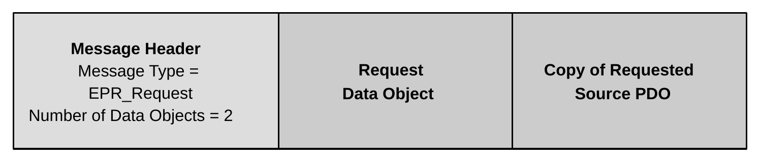
Note: This differs from the Request Message, which only contains a single RDO.
Note: The requested Power Data Object (PDO) May be an EPR PDO or APDO or an SPR PDO or APDO.
6.4.9. EPR_Mode Message
The EPR_Mode Message is used to enter, acknowledge, and exit the EPR Mode.
This Message is used in the following sequences:
- EPR Mode Enter
- EPR Mode Exit
Usage: Section 7.30
Table 6.28. EPR Mode Data Object (EPRMDO)
| Bit(s) | Field Name | Static | Description |
|---|---|---|---|
| 31...24 | Action | No | 01h - Enter EPR Mode (sent by Sink only). 02h - Enter Acknowledged (sent by Source only). 03h - Enter Succeeded (sent by Source only). 04h - Enter Failed (sent by Source only). 05h - Exit EPR Mode (sent by Source/Sink). All other values are Invalid; receiver Should ignore this Message. |
| 23...16 | Data | No | If Action is 01h (Enter EPR Mode): 00h-FFh - EPR Sink Operational PDP (this Shall match the "EPR Sink Operational PDP" field in Sink_Capabilities_Extended Message). If Action is 02h (Enter Acknowledged): Reserved, receiver Shall ignore this field. If Action is 03h (Enter Succeeded): Reserved, receiver Shall ignore this field. If Action is 04h (Enter Failed): 00h - Unknown cause of failure. 01h - Cable not EPR Capable. 02h - Source failed to become VCONN Source. 03h - EPR Capable bit not set in RDO. 04h - Source unable to enter EPR Mode. The Sink May retry entering EPR Mode after receiving this Enter Failed response. 05h - EPR Capable bit not set in PDO. All other values are Invalid; receiver Should ignore this field. If Action is 05h (Exit EPR Mode): Reserved, receiver Shall ignore this field. |
| 15...0 | Reserved | Yes | Reserved, receiver Shall ignore this field. |
6.4.10. Source_Info Message
Used to convey the overall Capabilities of a Port to act as a Source Bit(s) Field Name Static Description. The Source_Info Message contains two Source Information Data Objects (SIDO1 and SIDO2).
This Message is used in the following sequences:
- Get Source Information
Usage: Section 7.26
Table 6.29. Source_Info Data Object 1 (SIDO1)
| Bit(s) | Field Name | Static | Description |
|---|---|---|---|
| 31 | Port Type | Yes | Indicates whether the amount of power the Port can provide is fixed or can change dynamically. 0b - Managed Capability Port. 1b - Guaranteed Capability Port. See Section 3.2 for description of Managed vs Guaranteed Capability. |
| 30...24 | Reserved | Yes | Reserved, receiver Shall ignore this field. |
| 23...16 | Port Maximum PDP | Yes | Maximum power the Port will provide in 1W steps. |
| 15...8 | Port Present PDP | No | Power the Port is presently capable of supplying in 1W steps, including limitations due to Cable Capabilities or abnormal operating conditions (e.g., elevated temperature, low input voltage, etc.). |
| 7...0 | Port Reported PDP | No | Power the Port is offering, in 1W steps, equal to the power offered in the Source_Capabilities Message or EPR_Source_Capabilities Message. Note: Computed as the integer part of, the largest of the products of the voltage times current of the Fixed Supply PDOs returned in the Source_Capabilities Message or EPR_Source_Capabilities Messages. May be Static for Guaranteed Capability Ports. |
Table 6.30. Source_Info Data Object 2 (SIDO2)
| Bit(s) | Field Name | Static | Description |
|---|---|---|---|
| 31 | Port Type | Yes | Indicates whether the amount of power the Port can provide is fixed or can change dynamically. 0b - Managed Capability Port. 1b - Guaranteed Capability Port. See Section 3.2 for description of Managed vs Guaranteed Capability. |
| 30 | DPS Port | Yes | Indicates whether the Source will behave as a Dynamic Power Source. 0b - Non DPS Port 1b - DPS Port (Port Type Shall be set to 0b in both SIDO1 and SIDO2) |
| 29...18 | Reserved | Yes | Reserved, receiver Shall ignore this field. |
| 17...9 | Port Maximum PDP | Yes | Maximum power the Port will provide in 0.5W steps. |
| 8...0 | Port Guaranteed PDP | Yes | Minimum power the Port is guaranteed to always be able to provide in 0.5W steps. |
6.4.11. Revision Message
This Message is used to identify the highest PD Specification Revision at which the Port is capable of operating.
This Message is used in the following sequences:
- Get Revision
Usage: Section 7.25
Table 6.31. Revision Message Data Object (RMDO)
| Bit(s) | Field Name | Static? | Description |
|---|---|---|---|
| 31...28 | Revision Major | Yes | Major Value of PD Revision. |
| 27...24 | Revision Minor | Yes | Minor Value of PD Revision. |
| 23...20 | Version Major | Yes | Major Value of PD Version. |
| 19...16 | Version Minor | Yes | Minor Value of PD Version. |
| 15...0 | Reserved | Yes | Reserved, receiver Shall ignore this field. |
As an example, Revision 3.2, Version 1.2 would be represented as: 0x32120000.
6.4.12. Vendor Defined Message
The Vendor_Defined Message (VDM) is provided to allow vendors to exchange information outside of that defined by this specification.
A Vendor_Defined Message Shall consist of at least one Vendor Data Object (VDO), the VDM Header, and May contain up to a maximum of six additional VDOs.
To ensure vendor uniqueness of Vendor_Defined Messages, all Vendor_Defined Messages Shall contain a Valid USB Standard or Vendor ID (SVID) allocated by USB-IF in the VDM Header.
Two types of Vendor_Defined Messages are defined: Structured VDMs and Unstructured VDMs. A Structured VDM defines an extensible structure designed to support Modal Operation. An Unstructured VDM does not define any structure and Messages May be created in any manner that the vendor chooses.
Vendor_Defined Messages Shall Not be used for direct power Negotiation. They May however be used to alter Local Policy, affecting what is offered or consumed via the normal PD Messages. The Message format Shall be as shown in Figure 6.4.
Figure 6.4. Figure: Vendor Defined Message

The VDM Header Shall be the first 4-byte object in a Vendor Defined Message. The VDM Header provides Command space to allow vendors to customize Messages for their own purposes. Additionally, vendors May make use of the Commands in a Structured VDM.
The fields in the VDM Header for an Unstructured VDM, when the VDM Type Bit is set to zero, Shall be as defined in Table 6.32 . The fields in the VDM Header for a Structured VDM, when the VDM Type Bit is set to one Shall be as defined in Table 6.33 .
This Message is used in the following sequences:
- Discover Identity (SVDM)
- Discover SVIDs (SVDM)
- Discover Modes (SVDM)
- Enter Mode (SVDM)
- Exit Mode (SVDM)
- Structured VDM (Other)
6.4.12.1. Unstructured VDM
The Unstructured VDM does not define the contents of bits 14...0 in the VDM Header. Their definition and use are the sole responsibility of the vendor indicated by the VID. The Port Partners and Cable Plugs Shall exit any states entered using an Unstructured VDM when a Hard Reset appears on PD.
Usage: Section 8.4
Table 6.32. Unstructured VDM Header
| Bit(s) | Parameter | Static | Description |
|---|---|---|---|
| 31...16 | Vendor ID (VID) | Yes | Unique 16-bit unsigned integer. Assigned by the USB-IF to the Vendor. The Vendor ID (VID) field Shall contain the 16-bit Vendor ID value assigned to the vendor by the USB-IF (VID). No other value Shall be present in this field. |
| 15 | VDM Type | Yes | 0 = Unstructured VDM The VDM Type field Shall be set to zero indicating that this is an Unstructured VDM. |
| 14...0 | Available for Vendor Use | No | Content of this field is defined by the vendor. |
6.4.12.2. Structured VDM
Setting the VDM Type field to 1 (Structured VDM) defines the use of bits B14...0 in the Structured VDM Header. The fields in the Structured VDM Header are defined in Table 6.33 .
Usage: Section 8.5
Table 6.33. Structured VDM Header
| Bit(s) | Field Name | Static | Description |
|---|---|---|---|
| 31...16 | Standard or Vendor ID (SVID) | Yes | 16-bit USB Standard ID value (SID) or the 16-bit assigned to the vendor by the USB-IF (VID). No other value Shall be present in this field. SVID values referenced by this specification include 0xFF00 - PD SID allocated to this specification by USB-IF 0xFF01 - DPTC SID allocated to [DPTC] by USB-IF. |
| 15 | VDM Type | Yes | 1 = Structured VDM. |
| 14...13 | Structured VDM Version (Major) | Yes | Version Number (Major) of the Structured VDM (not this specification). This field indicates the expected content for this VDO. 00b - Version 1.0 (Used by USB PD implementations conforming to USB PD Revision 3.0, Version 1.0 - Deprecated for new designs). 01b - Version 2.x (Used by USB PD R3.x implementations starting with USB PD Revision 3.0, Version 1.0a). 10b...11b - Invalid, receiver uses 01b (Version 2.x) |
| Bit(s) | Field Name | Static | Description |
|---|---|---|---|
12...11 |
Structured VDM Version (Minor) | Yes | Version Number (Minor) of the Structured VDM (not this specification). This field indicates the expected content for this VDO. When Command = 0...15: 00b - Version 2.0 (Used for ports implemented prior to USB PD Revision 3.1, Version 1.6).01b - Version 2.1 (Used for ports implemented starting with USB PD Revision 3.1, Version 1.6)10b...11b - Invalid, Shall Not be usedWhen Command = 16...31 : 00b...11b - Defined by the SVID. |
10...8 |
Object Position | No | Shall be used by the Enter Mode, Exit Mode and Attention commands to indicate which VDO (e.g., Alternate Mode) the Command refers to. When Command = 0...3, 7...15: 000b - Shall be used.001b...111b - Invalid; receiver Should ignore this field.When Command = 4...6: 000b = Invalid, Shall Not be used.001b...110b = Index into the list of VDOs to identify the desired Alternate Mode VDO. Values greater than the number of VDOs supplied by Discover Modes ACK are Invalid.111b = Exit all Active Modes (equivalent of a power on reset). Shall only be used with the Exit Mode Command.When Command = 16...31: 000b - 111b - defined by the SVIDSee Table 6.33 . |
7...6 |
Command Type | No | Shall be used to indicate the type of Command Request/response being sent.00b - REQ (Request from Initiator Port)01b - ACK (Acknowledge Response from Responder Port)10b - NAK (Negative Acknowledge Response from Responder Port)11b - BUSY (Busy Response from Responder Port)See Table 6.33 . |
5 |
Reserved | Yes | Reserved, receiver Shall ignore this field. |
| Bit(s) | Field Name | Static | Description |
|---|---|---|---|
4...0 |
Command | No | VDM Command being sent.0 - Invalid; receiver Shall respond with NAK.1 - Discover Identity2 - Discover SVIDs3 - Discover Modes4 - Enter Mode5 - Exit Mode6 - Attention7...15 - Invalid; receiver Shall respond with NAK.16...31 - SVID Specific CommandsSee Table 6.32 . |
6.4.12.2.1. Structured VDM Version
The Structured VDM Version (Major)/Structured VDM Version (Minor) fields indicate the level of functionality supported in the Structured VDM part of the specification. This is not the same Version as the Version of this specification. The Structured VDM Version (Major) Shall be set to 01b to indicate Version 2.x with the Structured VDM Version (Minor) field set as appropriate based on whether the Port is implemented to USB PD Revision 3.1, Version 1.6 (or newer) or a prior Version.
6.4.12.2.2. Object Position
The Object Position field Shall be used by the Enter Mode and Exit Mode Commands. The Discover Modes Command returns a list of zero to six VDOs, each of which describes an Alternate Mode. The value in Object Position field is an index into that list that indicates which VDO (e.g., Alternate Mode) in the list the Enter Mode and Exit Mode Command refers to. The Object Position Shall start with one for the first Alternate Mode in the list.
This field Shall be set to zero in the Request or Response (REQ, ACK, NAK or BUSY) when not required by the specification of the individual Command.
6.4.12.2.3. Command Type
This Command Type field Shall be used to indicate the type of Command Request/response being sent.
An Initiator Shall set the Command Type field to REQ to indicate that this is a Command Request from an Initiator. If Structured VDMs are supported, then the responses are as follows:
- "Responder ACK" is the normal return and Shall be sent to indicate that the Command Request was received and handled normally.
- "Responder NAK" Shall be returned when the Command Request meets one of the following criteria:
- Has an Invalid parameter (e.g., Invalid SVID or Alternate Mode).
- Cannot be acted upon because the configuration is not correct (e.g., an Alternate Mode which has a dependency on another Alternate Mode or a Request to exit an Alternate Mode which is not an Active Mode).
- Is an Unrecognized Message.
- The handling of "Responder NAK" is left up to the Initiator.
- A "Responder BUSY" Shall be sent in the response to a VDM when the Responder is unable to immediately respond to the Command Request, but the Command Request May be retried.
6.4.12.2.4. Command
The Command field contains the value for the VDM Command being sent. The Commands explicitly listed in the Command field are used to identify devices and manage their operational Modes. There is a further range of Command values left for the vendor to use to manage additional extensions.
6.4.12.3. Discover Identity
The Discover Identity Command is provided to enable an Initiator to identify its Port Partner and for an Initiator (VCONN Source) to identify the Responder (Cable Plug or VPD). The Discover Identity Command is also used to determine whether a Cable Plug or VPD is PD-Capable by looking for a GoodCRC Message Response.
If the product is a DRD, the ID Header VDO Shall declare both a Product Type (UFP) and a Product Type (DFP). The Discover Identity ACK Shall contain Product Type VDOs for both UFP and DFP beginning with the UFP VDO, followed by a 32-bit Pad Object (defined as all 0s), followed by the DFP VDO as shown in Figure 6.5.
Figure 6.5. Discover Identity Response Format
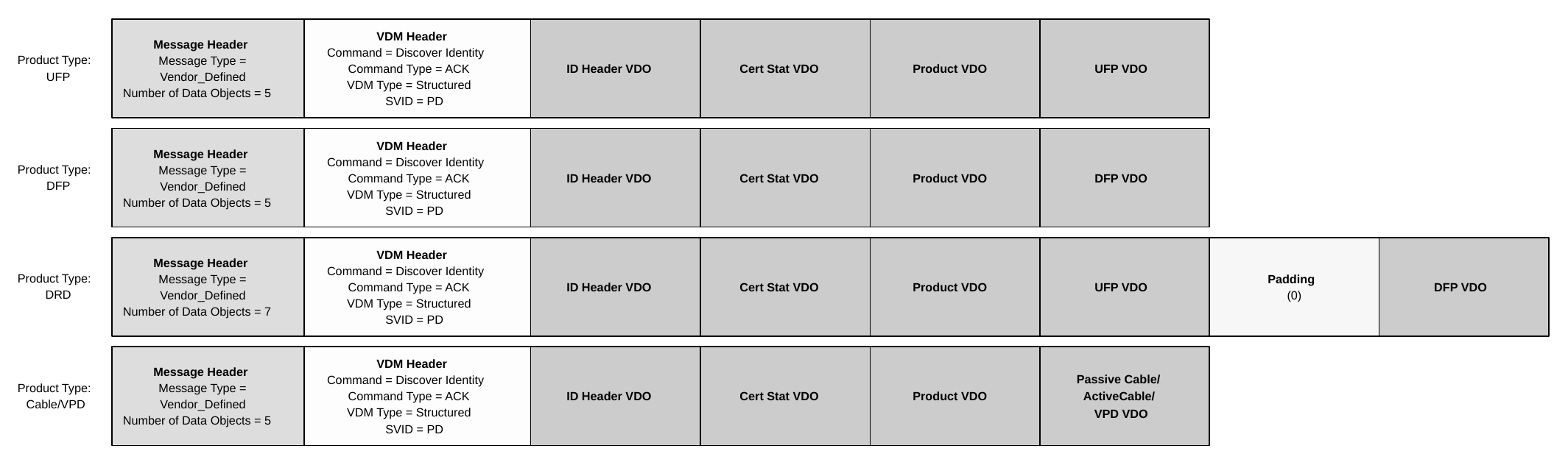
Usage: Section 8.6.1
6.4.12.3.1. ID Header VDO
The ID Header VDO contains information corresponding to the Power Delivery Product.
Table 6.34. ID Header VDO
| Bit(s) | Field Name | Static | Description |
|---|---|---|---|
31 |
Communications Capable as USB Host | Yes | 0b - Product is not capable of enumerating USB Devices.1b - Product is capable of enumerating USB Devices. |
30 |
Communications Capable as USB Device | Yes | 0b - Product is not capable of being enumerated as a USB Device.1b - Product is capable of being enumerated as a USB Device. |
| Bit(s) | Field Name | Static | Description |
|---|---|---|---|
29...27 |
Product Type (UFP/Cable Plug/VPD) | Yes | SOP (UFP):000b - Not a UFP001b - PDUSB Hub010b - PDUSB Peripheral011b - PSD100b - Invalid; receiver Should ignore this field101b - Deprecated, Alternate Mode Adapter (AMA)110b...111b - Invalid; receiver Should ignore this fieldSOP' (Cable Plug/VPD): 000b - Not a Cable Plug/VPD001b...010b - Invalid; receiver Should ignore this field011b - Passive Cable100b - Active Cable101b - Invalid; receiver Should ignore this field110b - VCONN Powered USB Device (VPD)111b - Invalid, Shall Not be use |
26 |
Modal Operation Supported | Yes | Shall indicate whether or not the Product (either a Cable Plug or a Device that can operate in the UFP role) is capable of supporting Modes. A product that supports Modal Operation Shall respond to the Discover SVIDs Command with a list of SVIDs for all of the Modes it is capable of supporting whether or not those Modes can currently be entered.0b - Product is not capable of supporting Modal Operation.1b - Product is capable of supporting Modal Operation.Note: The Modal Operation Supported bit does not describe a DFP's Alternate Mode Controller functionality. |
25...23 |
Product Type (DFP) | Yes | SOP (DFP):000b - Not a DFP001b - PDUSB Hub010b - PDUSB Host011b - Power Brick100b - Deprecated, Alternate Mode Controller (AMC).101b...111b - Invalid, Shall Not be used.SOP': Reserved, Shall Not be used. See Section 6.4.12.3.1 . |
22...21 |
Connector Type | Yes | 00b - Deprecated, Unknown connector type01b - Invalid, Shall Not be used.10b - USB Type-C Receptacle11b - USB Type-C Plug |
| Bit(s) | Field Name | Static | Description |
|---|---|---|---|
20...16 |
Reserved | Yes | Reserved, receiver Shall ignore this field. |
15...0 |
USB Vendor ID | Yes | Vendor ID assigned to the product vendor by USB-IF. For USB Devices or Hubs which support USB Communications the USB Vendor ID field Shall be identical to the Vendor ID field defined in the product's USB Device Descriptor (see [USB2] and [USB3]). See Section 6.1.5. |
6.4.12.3.2. Product Type (UFP/Cable Plug/VPD)
6.4.12.3.2.1. SOP (UFP)
The SOP Product Type (UFP) field indicates the type of Product when in UFP Data Role, whether a VDO will be returned and if so the type of VDO to be returned. The Product Type indicated in the SOP Product Type (UFP) field Shall be the closest categorization of the main functionality of the Product in UFP Data Role or "Undefined" when there is no suitable category for the product. For DRD Products this field Shall always indicate the Product Type when in UFP role regardless of the present Data Role. Table 6.35 defines the Product Type VDOs which Shall be returned.
Table 6.35. Product Types (UFP)
| Field Name | Product Type | Description | VDO |
|---|---|---|---|
| Product Type (UFP/Cable Plug/VPD) | Not a UFP | Shall be used when this is not a UFP. | None |
| Product Type (UFP/Cable Plug/VPD) | PDUSB Hub | Shall be used when the Product is a PDUSB Hub. | UFP VDO |
| Product Type (UFP/Cable Plug/VPD) | PDUSB Peripheral | Shall be used when the Product is a PDUSB Device other than a PDUSB Hub. | UFP VDO |
| Product Type (UFP/Cable Plug/VPD) | PSD | Shall be used with the Product is a PSD (e.g., power bank). | None |
6.4.12.3.2.2. SOP' (Cable Plug/VPD)
The SOP' Product Type (Cable Plug/VPD) field indicates the type of Product when the Product is a Cable Plug or VPD, whether a VDO will be returned and if so the type of VDO to be returned. Table 6.36 defines the Product Type VDOs which Shall be returned.
Table 6.36. Product Types (Cable Plug/VPD)
| Field Name | Product Type | Description | VDO |
|---|---|---|---|
| Product Type (UFP/Cable Plug/VPD) | Not a Cable Plug/VPD | Shall be used where no other Product Type value is appropriate. | None |
| Product Type (UFP/Cable Plug/VPD) | Active Cable | Shall be used when the Product is a cable that incorporates signal conditioning circuits. | Active Cable VDO |
| Product Type (UFP/Cable Plug/VPD) | Passive Cable | Shall be used when the Product is a cable that does not incorporate signal conditioning circuits. | Passive Cable VDO |
| Product Type (UFP/Cable Plug/VPD) | VCONN Powered USB Device | Shall be used when the Product is a PDUSB VCONN Powered USB Device. | VPD VDO |
6.4.12.3.3. Product Type (DFP)
6.4.12.3.3.1. SOP (DFP)
The SOP - Product Type (DFP) field indicates the type of Product when in DFP Data Role, whether a VDO will be returned and if so the type of VDO to be returned. The Product Type indicated in the SOP - Product Type (DFP) field Shall be the closest categorization of the main functionality of the Product in DFP Data Role or "Undefined" when there is no suitable category for the product. For DRD Products this field Shall always indicate the Product Type when in DFP role regardless of the present Data Role. Table 6.37 defines the Product Type VDOs which Shall be returned.
In SOP' Communication (Cable Plugs and VPDs) this bit field is Reserved and Shall be set to zero.
Where there is no Product Type VDO defined for a specific Product Type, no VDOs Shall be sent as part of the Discover Identity Command response.
Table 6.37. Product Type (DFP)
| Field Name | Product Type | Description | VDO |
|---|---|---|---|
| Product Type (DFP) | Not a DFP | Shall be used where no other Product Type value is appropriate. | None |
| Product Type (DFP) | PDUSB Hub | Shall be used when the Product is a PDUSB Hub. | DFP VDO |
| Product Type (DFP) | PDUSB Host | Shall be used when the Product is a PDUSB Host or a PDUSB Host that supports one or more Alternate Modes as and AMC. | DFP VDO |
| Product Type (DFP) | Power Brick | Shall be used when the Product is a Power Brick. | DFP VDO |
6.4.12.3.4. Cert Stat VDO
The Cert Stat VDO Shall contain the XID assigned by USB-IF to the product before certification in binary format. If the vendor does not have an XID, then it Shall return zero in this field.
Table 6.38. Cert Stat VDO
| Bit(s) | Field Name | Static | Description |
|---|---|---|---|
31...0 |
XID | Yes | Value provided by the USB-IF and assigned to the product by the vendor. |
6.4.12.3.5. Product VDO
The Product VDO contains identity information relating to the product.
Table 6.39. Product VDO
| Bit(s) | Field Name | Static | Description |
|---|---|---|---|
31...16 |
USB Product ID | Yes | Product ID assigned to the Port by the Vendor. See Section 6.1.5 |
15...0 |
bcdDevice | Yes | Device Version assigned to the Port by the Vendor |
Manufacturers Should set the USB Product ID field to a unique value identifying the product and Should set the bcdDevice field to a Version number relevant to the release Version of the product.
6.4.12.3.6. UFP VDO
The UFP VDO defined in this section Shall be returned by Ports capable of operating as a UFP including traditional USB peripherals, USB Hub's upstream Port and DRD capable Host Ports. The UFP VDO defined in this section Shall be sent when the Product Type (UFP) field in the ID Header VDO is given as a PDUSB Peripheral or PDUSB Hub.
A [USB4] UFP Shall support the Structured VDM Discover Identity Command.
Table 6.40. UFP VDO
| Bit(s) | Field Name | Static | Description |
|---|---|---|---|
31...29 |
UFP VDO Version | Yes | Version Number of the VDO (not this specification Version). This field indicates the expected content for the UFP VDO.000b - Invalid, Shall Not be used.001b - Deprecated, Version 1.1010b - Deprecated, Version 1.2011b - Version 1.3100b...111b - Invalid, Shall Not be used. |
28 |
Reserved | Yes | Reserved, receiver Shall ignore this field. |
27 |
USB4 Device Capability | Yes | UFP's Capability when operating as either a PDUSB Device or PDUSB Hub.0b - Device is not USB4 capable.1b - Device is USB4 capable. |
26 |
USB 3.2 Device Capability | Yes | UFP's Capability when operating as either a PDUSB Device or PDUSB Hub.0b - Device is not USB 3.2 capable1b - Device is USB 3.2 capable |
25..24 |
USB 2.0 Device Capability | Yes | UFP's Capability when operating as either a PDUSB Device or PDUSB Hub.00b - Device is not USB 2.0 capable.01b - Device is USB 2.0 capable of USB 2.0 as a billboard Device only.10b - Device is capable of USB 2.0.11b - Invalid, receiver Shall assume 00b. |
23...22 |
Connector Type (Legacy) | Yes | Deprecated. Shall be set to 00b, and Shall be Ignored by the receiver.The Connector Type (Legacy) field was previously used for the UFP VDO's Connector Type. The receiver can find this information in the Connector Type field in the ID Header VDO. |
21...11 |
Reserved | Yes | Reserved, receiver Shall ignore this field. |
| Bit(s) | Field Name | Static | Description |
|---|---|---|---|
10...8 |
VCONN Power | Yes | When the VCONN Required field is set to "Yes" the VCONN Power Field indicates the VCONN power needed by the AMA for full functionality:000b - 1W001b - 1.5W010b - 2W011b - 3W100b - 4W101b - 5W110b - 6W111b - Invalid, Shall Not be used.When the VCONN Required field is set to "No" the VCONN Power field is Reserved and Shall be set to zero. |
7 |
VCONN Required | Yes | Indicates whether the AMA requires VCONN in order to Function.0b - No1b - YesWhen the Alternate Mode fields indicate no modes are supported, the VCONN Required field is Reserved and Shall be set to zero. |
6 |
VBUS Required | Yes | Indicates whether the AMA requires VBUS in order to function.0b - Yes1b - NoWhen the Alternate Mode fields indicate no modes are supported, the VBUS Required field is Reserved and Shall be set to zero. |
5 |
No Signal Reconfig. Alternate Mode Support | Yes | Indicates support for Alternate Modes that do not reconfigure the signals on the [USB-C] connector.0b - No1b - Yes |
4 |
Non-[TBT3] Signal Reconfig. Alternate Mode Support | Yes | Indicates support for Alternate Modes that reconfigure the signals on the [USB-C] connector - except for [TBT3]0b - No1b - Yes |
3 |
[TBT3] Alternate Mode Support | Yes | Indicates support for [TBT3] Alternate Mode0b - No1b - Yes |
| Bit(s) | Field Name | Static | Description |
|---|---|---|---|
| 2...0 | USB Highest Speed | Yes | Port's highest speed capability. 000b - [USB2] only, no SuperSpeed support 001b - [USB3] Gen1 010b - [USB3]/[USB4] Gen2 011b - [USB4] Gen3 100b - [USB4] Gen4 101b...111b - Invalid, Shall Not be used. Note: The DFP Shall consider all values, including Invalid, indicated in this field that are higher than the highest value that the DFP recognizes as being Valid and functionally compatible with the highest speed that the DFP supports. |
6.4.12.3.7. DFP VDO
The DFP VDO Shall be returned by Ports capable of operating as a DFP; including those implemented by Hosts, Hubs and Power Bricks. The DFP VDO Shall be returned when the Product Type (DFP) field in the ID Header VDO is given as Power Brick, PDUSB Host or PDUSB Hub.
Table 6.41. DFP VDO
| Bit(s) | Field Name | Static | Description |
|---|---|---|---|
| 31...29 | DFP VDO Version | Yes | Version Number of the VDO (not this specification Version). This field indicates the expected content for the DFP VDO. 000b - Invalid, Shall Not be used. 001b - Deprecated, Version 1.1 010b - Version 1.2 011b...111b - Invalid, Shall Not be used. |
| 28...27 | Reserved | Yes | Reserved, receiver Shall ignore this field. |
| 26 | USB 4 Host Capability | Yes | DFP's Capability when operating as a PDUSB Hub. 0b - Host is not USB 4 capable 1b - Host is USB 4 capable |
| 25 | USB 3.2 Host Capability | Yes | DFP's Capability when operating as a PDUSB Host. 0b - Host is not USB 3.2 capable. 1b - Host is USB 3.2 capable. Power Bricks and PDUSB Hubs Shall set to zero. |
| 24 | USB 2.0 Host Capability | Yes | DFP's Capability when operating as a PDUSB Host. 0b - Device is not USB 2.0 capable. 1b - Device is USB 2.0 capable. Power Bricks and PDUSB Hubs Shall set to zero. |
| 23...22 | Connector Type (Legacy) | Yes | Deprecated. Shall be set to 00b, and Shall be Ignored by the receiver.The Connector Type (Legacy) field was previously used for the UFP VDO's Connector Type. The receiver can find this information in the Connector Type field in the ID Header VDO (Section 6.4.12.3.1). |
| 21...5 | Reserved | Yes | Reserved, receiver Shall ignore this field. |
| 4...0 | Port Number | Yes | Unique number that unambiguously identifies each [USB-C] DFP, including DRPs, on the Device. This number is independent of the USB Port number. |
6.4.12.3.8. Passive Cable VDO
The Passive Cable VDO defined in this section Shall be sent when the Product Type is given as Passive Cable.
A Passive Cable has a USB Plug on each end at least one of which is a Cable Plug supporting SOP' Communication. A Passive Cable Shall Not incorporate data bus signal conditioning circuits and hence has no concept of Super Speed Directionality. A Passive Cable Shall include a VBUS wire and Shall only respond to SOP' Communication. Passive Cables Shall support the Structured VDM Discover Identity Command and Shall return the Passive Cable VDO in a Discover Identity Command ACK.
Table 6.42. Passive Cable VDO
| Bit(s) | Field Name | Static | Description |
|---|---|---|---|
| 31...28 | Hardware Version | Yes | 0000b...1111b - HW Version assigned by the VID owner. |
| 27...24 | Firmware Version | Yes | 0000b...1111b - FW Version assigned by the VID owner. |
| Bit(s) | Field Name | Static | Description |
|---|---|---|---|
| 23...21 | VDO Version | Yes | Version Number of the VDO (not this specification Version). This field indicates the expected content for this VDO. 000b - Version 1.0 001b...111b - Invalid, Shall Not be used. |
| 20 | Reserved | Yes | Reserved, receiver Shall ignore this field. |
| 19...18 | USB Type-C plug to USB Type-C/Captive (Passive Cable) | Yes | Indicates whether the opposite end from the USB Type-C plug is another USB Type-C plug (i.e., a detachable Standard USB Type-C Cable Assembly) or is a Captive Cable Assembly. 00b - Deprecated, USB Type-A 01b - Deprecated, USB Type-B 10b - USB Type-C 11b - Captive |
| 17 | EPR Capable (Passive Cable) | Yes | Indicates when the cable is specifically designed for safe operation when carrying up to 48 volts at 5 amps. 0b - Cable is not EPR Capable 1b - Cable is EPR Capable |
| 16...13 | Cable Latency (Passive Cable) | Yes | Signal latency through the cable which can be used as an approximation for its length. 0000b - Invalid, Shall Not be used 0001b - <10ns (~1m) 0010b - 10ns to 20ns (~2m) 0011b - 20ns to 30ns (~3m) 0100b - 30ns to 40ns (~4m) 0101b - 40ns to 50ns (~5m) 0110b - 50ns to 60ns (~6m) 0111b - 60ns to 70ns (~7m) 1000b - > 70ns (>~7m) 1001b....1111b - Invalid, Shall Not be used |
| 12...11 | Cable Termination Type (Passive Cable) | Yes | Indicates whether the Passive Cable needs VCONN only initially in order to support the Discover Identity Command, after which it can be removed, or the Passive Cable needs VCONN to be continuously applied in order to power some feature of the Cable Plug. 00b - VCONN not required. Cable Plugs that only support Discover Identity Commands Shall set these bits to 00b.01b - VCONN required 10b...11b - Invalid, Shall Not be used. |
| Bit(s) | Field Name | Static | Description |
|---|---|---|---|
| 10...9 | Maximum VBUS Voltage (Passive Cable) | Yes | Maximum voltage that Shall be Negotiated using a Fixed Supply over the cable as part of an Explicit Contract where the maximum voltage that Shall be applied to the cable is vSrcNew max + vSrcValid max. For example, when the Maximum VBUS Voltage (Passive Cable) field is 20V, a Fixed Supply of 20V can be Negotiated as part of an Explicit Contract where the absolute maximum voltage that can be applied to the cable is 21.55V. Similarly, when the Maximum VBUS Voltage (Passive Cable) field is 50V, a Fixed Supply of 48V can be Negotiated as part of an Explicit Contract where the absolute maximum voltage that can be applied to the cable is 50.9V. EPR Sinks with a captive cable Shall report 50V. 00b - 20V 01b..10b - Deprecated, receiver Shall assume 00b (20V).11b - 50V |
| 8...7 | Reserved | Yes | Reserved, receiver Shall ignore this field. |
| 6...5 | VBUS Current Handling Capability (Passive Cable) | Yes | Indicates whether the cable is capable of carrying 3A or 5A. 00b - Invalid; receiver Shall assume 01b (3A).01b - 3A 10b - 5A 11b - Invalid; receiver Shall assume 01b (3A). |
| 4...3 | Reserved | Yes | Reserved, receiver Shall ignore this field. |
| 2...0 | USB Highest Speed (Passive Cable) | Yes | Highest data rate the cable supports. 000b - [USB2] only, no SuperSpeed support. 001b - [USB3] Gen1 010b - [USB3]/[USB4] Gen2 011b - [USB4] Gen3 100b - [USB4] Gen4 101b...111b - Invalid, Shall Not be used. Note: The DFP Shall consider all values, including Invalid, indicated in this field that are higher than the highest value that the DFP recognizes as being Valid and functionally compatible with the highest speed that the DFP supports. |
6.4.12.3.9. Active Cable VDOs
An Active Cable has a USB Plug on each end at least one of which is a Cable Plug supporting SOP' Communication. An Active Cable Shall incorporate data bus signal conditioning circuits and May have a concept of Super Speed Directionality on its Super Speed wires. An Active Cable May include a VBUS wire.
An Active Cable:
- Shall respond to SOP' Communication.
- May respond to SOP'' Communication.
- Shall support the Structured VDM Discover Identity Command.
- In the Discover Identity Command ACK:
- Shall set the Product Type in the ID Header VDO to Active Cable.
- Shall return the Active Cable VDOs.
Table 6.43. Active Cable VDO1
| Bit(s) | Field Name | Static | Description |
|---|---|---|---|
| 31...28 | Hardware Version | Yes | 0000b...1111b - HW Version assigned by the VID owner. |
| 27...24 | Firmware Version | Yes | 0000b...1111b - FW Version assigned by the VID owner. |
| 23...21 | VDO Version | Yes | Version Number of the VDO (not this specification Version). This field indicates the expected content for this VDO. 000b - Deprecated, Version 1.0 001b - Invalid, Shall Not be used. 010b - Deprecated, Version 1.2 011b - Version 1.3 100b...111b - Invalid, Shall Not be used. |
| 20 | Reserved | Yes | Reserved, receiver Shall ignore this field. |
| 19...18 | USB Type-C plug to USB Type-C/Captive (Active Cable) | Yes | Indicates whether the opposite end from the USB Type-C plug is another USB Type-C plug (i.e., a detachable Standard USB Type-C Cable Assembly) or is a Captive Cable Assembly. 00b - Deprecated, USB Type-A 01b - Deprecated, USB Type-B 10b - USB Type-C 11b - Captive |
| 17 | EPR Capable (Active Cable) | Yes | Indicates when the cable is specifically designed for safe operation when carrying up to 48 volts at 5 amps. 0b - Cable is not EPR Capable 1b - Cable is EPR Capable |
| 16...13 | Cable Latency | Yes | Signal latency through the cable which can be used as an approximation for its length. 0000b - Invalid, Shall not be used. 0001b - <10ns (~1m) 0010b - 10ns to 20ns (~2m) 0011b - 20ns to 30ns (~3m) 0100b - 30ns to 40ns (~4m) 0101b - 40ns to 50ns (~5m) 0110b - 50ns to 60ns (~6m) 0111b - 60ns to 70ns (~7m) 1000b - 1000ns (~100m) 1001b - 2000ns (~200m) 1010b - 3000ns (~300m) 1011b ....1111b - Invalid, Shall Not be used. Note: Includes latency of electronics in Active Cable. |
| Bit(s) | Field Name | Static | Description |
|---|---|---|---|
| 12...11 | Cable Termination Type (Active Cable) | Yes | Shall contain a value corresponding to whether the Active Cable has one or two Cable Plugs requiring power from VCONN. 00b...01b - Invalid, Shall Not be used. 10b - One end Active, one end passive, VCONN required. 11b - Both ends Active, VCONN required. |
| 10...9 | Maximum VBUS Voltage (Active Cable) | Yes | Maximum voltage that Shall be Negotiated as part of an Explicit Contract where the maximum voltage that Shall be applied to the cable is vSrcNew max + vSrcValid max. When this field is set to 20V, the cable will safely carry a Programmable Power Supply APDO of 20V where the absolute maximum voltage that can be applied to the cable is 21.55V. Similarly, when the Maximum VBUS Voltage (Active Cable) field is 50V, a Fixed Supply of 48V can be Negotiated as part of an Explicit Contract where the absolute maximum voltage that can be applied to the cable is 50.9V. EPR Sinks with a captive cable Shall report 50V. 00b - 20V 01b..10b - Deprecated, receiver Shall assume 00b (20V).11b - 50V |
| 8 | SBU Supported | Yes | Indicates whether the cable supports the SBUs in the cable. 0b - SBU connections supported. 1b - SBU connections are not supported. |
| 7 | SBU Type | Yes | Indicates whether the SBUs are passive or active (e.g., digital). When SBU Supported = 1 (SBU connections are not supported) this bit Shall be Ignored. When SBU Supported = 0 (SBU connections are supported): 0b - SBU is passive 1b - SBU is active |
| 6...5 | VBUS Current Handling Capability (Active Cable) | Yes | Indicates whether the cable is capable of carrying 3A or 5A. Shall be ignored when VBUS Through Cable = 0 00b - Invalid, Shall Not be used 01b - 3A 10b - 5A 11b - Invalid, Shall Not be used. |
| 4 | VBUS Through Cable | Yes | Indicates whether the cable contains an end-to-end VBUS wire. 0b - No 1b - Yes |
| 3 | SOP'' Controller Present | Yes | Indicates whether one of the Cable Plugs is capable of SOP'' Communication in addition to the Required SOP' Communication. 0b - No SOP'' controller present 1b - SOP'' controller present |
| Bit(s) | Field Name | Static | Description |
|---|---|---|---|
| 2...0 | USB Highest Speed (Active Cable) | Yes | Highest data rate the cable supports. 000b - [USB2] only, no SuperSpeed support 001b - [USB3] Gen1 010b - [USB3]/[USB4] Gen2 011b - [USB4] Gen3 100b - [USB4] Gen4 101b...111b - Invalid, and Shall Not be used Note: The DFP Shall consider all values, including Invalid, indicated in this field that are higher than the highest value that the DFP recognizes as being Valid and functionally compatible with the highest speed that the DFP supports. |
Table 6.44. Active Cable VDO2
| Bit(s) | Field Name | Static | Description |
|---|---|---|---|
| 31...24 | Maximum Operating Temperature | Yes | Maximum allowable operating temperature inside the plug in °C. It may reflect the plug's skin temperature |
| 23...16 | Shutdown Temperature | Yes | Temperature inside the plug, in °C, at which the plug will shut down its active Signaling components. When this temperature is reached, it will be reported in the Active Cable Status Message through the Thermal Shutdown bit. |
| 15 | Reserved | Yes | Reserved, receiver Shall ignore this field. |
| 14...12 | U3/CLd Power | Yes | Power the cable consumes while in [USB3] U3 or [USB4] CLd. 000b - >10mW 001b - 5-10mW 010b - 1-5mW 011b - 0.5-1mW 100b - 0.2-0.5mW 101b - 50-200μW 110b - <50μW 111b - Invalid; receiver Should assume 000b (>10mW) |
| 11 | U3 to U0 transition Mode | Yes | Indicates which U3 to U0 Mode the cable supports. This does not include the power in U3S if supported. 0b - U3 to U0 direct 1b - U3 to U0 through U3S |
| 10 | Physical Connection | Yes | Cable's construction, whether the connection between the active elements is copper or optical. 0b - Copper 1b - Optical |
| 9 | Active Element | Yes | Cable's active element, whether the active element is a re-timer or a re-driver. 0b - Active Re-driver 1b - Active Re-timer |
| Bit(s) | Field Name | Static | Description |
|---|---|---|---|
| 8 | USB4 Supported | Yes | Indicates whether or not the cable supports [USB4] operation. 0b - [USB4] supported 1b - [USB4] not supported. |
| 7...6 | USB 2.0 Hub Hops Consumed | Yes | Number of USB 2.0 'Hub hops' that are lost due to the transmission time of the cable. Shall be set to zero if USB 2.0 not supported. |
| 5 | USB 2.0 Supported | Yes | Indicates whether or not the cable supports [USB2] Signaling. 0b - [USB2] supported 1b - [USB2] not supported. |
| 4 | USB 3.2 Supported | Yes | Indicates whether or not the cable supports [USB3] SuperSpeed Signaling. 0b - [USB3] SuperSpeed supported. 1b - [USB3] SuperSpeed not supported. |
| 3 | USB Lanes Supported | Yes | Indicates whether the cable supports one or two lanes of [USB3] SuperSpeed Signaling. 0b - One lane 1b - Two lanes |
| 2 | Optically Isolated Active Cable | Yes | Indicates whether this cable is an optically isolated Active Cable or not (as defined in [USB-C]). Optically Isolated Active Cables Shall have a re-timer or linear re-driver (LRD) as the active element and do not support [USB2] or carry VBUS. 0b - No 1b - Yes |
| 1 | [USB4] Asymmetric Mode Supported | Yes | Active Cable supports asymmetric Mode as defined in [USB4] and [USB-C]. 0b - No 1b - Yes |
| 0 | USB Gen | Yes | Signaling Gen the cable supports. Gen 1 Shall only be used by [USB3] cables as indicated by the USB 3.2 Supported field. Gen 2 or higher May be used by either [USB3] or [USB4] cables as indicated by their respective supported fields. When Gen 2 or higher is indicated the USB Highest Speed (Active Cable) field in VDO1 Shall indicate the actual Gen supported. 0b - Gen 1 1b - Gen 2 or higher Note: See VDO1 USB Highest Speed for details of Gen supported. |
6.4.12.3.10. Alternate Mode Adapter
The Alternate Mode Adapter (AMA) VDO has been Deprecated. PDUSB Devices which support one or more Alternate Modes Shall set an appropriate Product Type (UFP), and Shall set the Modal Operation Supported bit to '1'.
6.4.12.3.11. VCONN Powered USB Device (VDO)
The VCONN Powered USB Device (VPD) VDO defined in this section Shall be sent when the Product Type is given as VCONN Powered USB Device.
Table 6.45. VCONN Powered USB Device VDO
| Bit(s) | Field Name | Static | Description |
|---|---|---|---|
| 31...28 | HW Version | Yes | 0000b..1111b - HW Version assigned by the VID owner. |
| 27...24 | Firmware Version | Yes | 0000b..1111b - FW Version assigned by the VID owner. |
| 23...21 | VDO Version | Yes | Version Number of the VDO (not this specification Version). This field indicates the expected content for this VDO.000b - Version 1.0001b...111b - Invalid, Shall Not be used. |
| 20...17 | Reserved | Yes | Reserved, receiver Shall ignore this field. |
| 16...15 | Maximum VBUS Voltage | Yes | Maximum voltage that a Sink Shall Negotiate through the VPD Charge Through Port as part of an Explicit Contract.00b - 20V01b..11b - Deprecated, receiver Shall assume 00b (20V). |
| 14 | Charge Through Current Support | Yes | Supported charge through current. When Charge Through Support = 0b, this is Reserved and Shall be set to 0.When Charge Through Support = 1b:0b - 3A capable.1b - 5A capable |
| 13 | Reserved | Yes | Reserved, receiver Shall ignore this field. |
| 12...7 | VBUS Impedance | Yes | Impedance the VPD adds in series between the Source and the Sink. The Sink Shall take this value into account when requesting current so as to not to exceed the VBUS IR Drop limit of 0.5V between the Source and itself. If the Sink can tolerate a larger IR Drop on VBUS it May do so. When Charge Through Support = 0b, this is Reserved and Shall not be used.When Charge Through Support = 1b:VBUS impedance through the VPD in 2 mΩ increments. Values less than 10 mΩ are Reserved and Shall Not be used. |
| 6...1 | Ground Impedance | Yes | Impedance the VPD adds in series between the Source and the Sink. The Sink Shall take this value into account when requesting current so as to not to exceed the Ground IR Drop limit of 0.25V between the Source and itself. When Charge Through Support = 0b, this is Reserved and Shall not be used.When Charge Through Current Support = 1b: Ground impedance through the VPD in 1 mΩ increments. Values less than 10 mΩ are Reserved and Shall Not be used. |
| 0 | Charge Through Support | Yes | Indicates whether the VPD supports Charge Through.0b - the VPD does not support Charge Through.1b - the VPD supports Charge Through. |
6.4.12.4. Discover SVIDs
The Discover SVIDs Command is used by an Initiator to determine the SVIDs for which a Responder has Modes. The Discover SVIDs Command is used in conjunction with the Discover Modes Command in the Discovery Process to determine which Modes a Device supports. The list of SVIDs is always terminated with one or two 0x0000 SVIDs.
The SVID in the Discover SVIDs Command Shall be set to the PD SID (see Table 6.33) by both the Initiator and the Responder for this Command.
The Number of Data Objects field in the Message Header in the Discover SVIDs Command Request Shall be set to 1 since the Discover SVIDs Command Request Shall Not contain any VDOs.
The Discover SVIDs Command ACK sent back by the Responder Shall contain one or more SVIDs. The SVIDs are returned 2 per VDO (see Table 6.46 "). If there are an odd number of supported SVIDs, the Discover SVIDs Command is returned ending with a SVID value of 0x0000 in the last part of the last VDO. If there are an even number of supported SVIDs, the Discover SVIDs Command is returned ending with an additional VDO containing two SVIDs with values of 0x0000. A Responder Shall only return SVIDs for which a Discover Modes Command Request for that SVID will return at least one Alternate Mode.
The Number of Data Objects field in the Message Header in the Discover SVIDs Command NAK and BUSY responses Shall be set to 1 since they Shall Not contain any VDOs.
Figure 6.6. Discover SVIDs Response Format
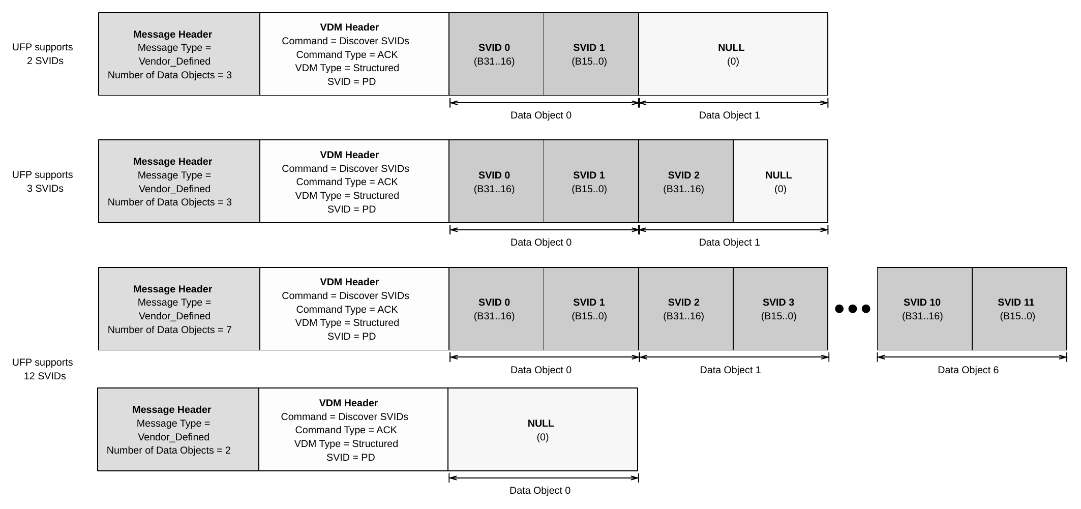
Usage: Section 8.6.2
6.4.12.4.1. Responder VDO
A Device that supports SVIDs Shall return them in the Discover SVIDs Command ACK. The SVIDs are returned 2 per VDO (see Table 6.46 "). If there are an odd number of supported SVIDs, the Discover SVIDs Command is returned ending with a SVID value of 0x0000 in the last part of the last VDO.
Table 6.46. Discover SVIDs Responder VDO
| Bit(s) | Field | Description |
|---|---|---|
| B31...16 | SVID n | 16-bit unsigned integer, assigned by the USB-IF or 0x0000 if this is the last VDO and the Responder supports an even number of SVIDs. |
| B15...0 | SVID n+1 | 16-bit unsigned integer, assigned by the USB-IF or 0x0000 if this is the last VDO and the Responder supports an odd or even number of SVIDs. |
6.4.12.5. Discover Mode
The Discover Modes Command is used by an Initiator to determine the Modes a Responder supports for a given SVID.
The SVID in the Discover Modes Command Shall be set to the SVID for which Modes are being requested by both the Initiator and the Responder for this Command.
The Number of Data Objects field in the Message Header in the Discover Modes Command Request Shall be set to 1 since the Discover Modes Command Request Shall Not contain any VDOs.
The Discover Modes CommandACK sent back by the Responder Shall contain one or more Modes. The Discover Modes Command ACK Shall contain a Message Header with the Number of Data Objects field set to a value of 2 to 7 (the actual value is the number of Alternate Mode objects plus one).
The Number of Data Objects field in the Message Header in the Discover Modes Command NAK and BUSY responses Shall be set to 1 since they Shall Not contain any VDOs.
Figure 6.7 shows an example of a Discover Modes Command response from a Responder which supports three Modes for a given SVID.
Figure 6.7. Example Discover Modes response for a given SVID with 3 Modes

Usage: Section 8.6.3
6.4.12.6. Enter Mode
The Enter Mode Command is used by an Initiator (DFP) to Command a Responder (UFP or Cable Plug) to enter a specified Alternate Mode of operation.
The value in the Object Position field in the VDM Header Shall indicate to which Alternate Mode in the Discover Modes Command the VDO refers. The value 1 always indicates the first Alternate Mode as it is the first object following the VDM Header. The value 2 refers to the next Alternate Mode and so forth.
The Number of Data Objects field in the Message Header in the Command Request Shall be set to either 1 or 2 since the Enter Mode Command Request Shall Not contain more than 1 VDO. When a VDO is included in an Enter Mode Command Request the contents of the 32-bit VDO is defined by the Alternate Mode.
The Number of Data Objects field in the Command response Shall be set to 1 since an Enter Mode Command response (ACK, NAK) Shall Not contain any VDOs.
Usage: Section 8.6.4
6.4.12.7. Exit Mode
The Exit Mode Command is used by an Initiator (DFP) to Command a Responder (UFP or Cable Plug) to exit its Active Mode and return to normal USB operation. Only the DFP Shall initiate the Exit Mode Process.
The value in the Object Position field Shall indicate to which Alternate Mode in the Discover Modes Command the VDO refers and Shall have been used previously in an Enter Mode Command Request for an Active Mode. The value 1 always indicates the first Alternate Mode as it is the first object following the VDM Header. The value 2
refers to the next Alternate Mode and so forth. A value of 111b in the Object Position field Shall indicate that all Active Modes Shall be exited.
The Number of Data Objects field in both the Command Request and Command response (ACK, NAK) Shall be set to 1 since an Exit Mode Command Shall Not contain any VDOs.
Usage: Section 8.6.5
6.4.12.8. Attention
The Attention Command May be used by the Initiator to notify the Responder that it requires service.
The Number of Data Objects field in the Message Header Shall be set to 1 or 2 since the Attention Command Shall Not contain more than 1 VDO. When a VDO is included in an Attention Command the contents of the 32-bit VDO is defined by the Alternate Mode.
The value in the Object Position field Shall indicate to which Alternate Mode in the Discover Modes Command the VDO refers (see Figure 6.7) and Shall have been used previously in an Enter Mode Command Request for an Active Mode. The value 1 always indicates the first Alternate Mode as it is the first object following the VDM Header. The value 2 refers to the next Alternate Mode and so forth. A value of 000b or 111b in the Object Position field Shall Not be used by the Attention Command.
Usage: Section 8.6.6
6.5. Extended Message
An Extended Message Shall contain a Message Header, an Extended Message Header (indicated by the Extended field in the Message Header being set), and be followed by zero or more data bytes. Additional bytes that might be added to existing Messages in future Revision of this specification Shall be Ignored.
Table 6.47. Extended Message Types
| Value | Message Type |
|---|---|
00000b |
Reserved, receiver Shall respond with Not_Supported Message |
00001b |
Source_Capabilities_Extended |
00010b |
Status Message |
00011b |
Get_Battery_Cap |
00100b |
Get_Battery_Status |
00101b |
Battery_Capabilities |
00110b |
Get_Manufacturer_Info |
00111b |
Manufacturer_Info |
01000b |
Security_Request |
01001b |
Security_Response |
01010b |
Firmware_Update_Request |
01011b |
Firmware_Update_Response |
01100b |
PPS_Status |
01101b |
Country_Info |
01110b |
Country_Codes |
01111b |
Sink_Capabilities_Extended |
10000b |
Extended_Control |
10001b |
EPR_Source_Capabilities |
10010b |
EPR_Sink_Capabilities |
| Value | Message Type |
|---|---|
10011b..11101b |
Reserved, receiver Shall respond with Not_Supported Message. |
11110b |
Vendor_Defined_Extended |
11111b |
Reserved, receiver Shall respond with Not_Supported Message. |
6.5.1. Extended Message Header
An Extended Messages (indicated by the Extended field being set in the Message Header) Shall contain an Extended Message Header following the Message Header as shown in Figure 6.2 and defined in Table 6.48.
Table 6.48. Extended Message Header Fields
| Bit(s) | Field Name | Applicable SOP | Description |
|---|---|---|---|
| 15 | Chunked | All | See Section 6.5.1.1 . |
| 14...11 | Chunk Number | All | When Chunked is 0b:Shall be 0 When Chunked is 1b and Request Chunk is 1b:0..9 - Chunk Number being requested. 10..15 - Invalid, receiver Shall ignore this Message. When Chunked is 1b and Request Chunk is 0b:0..9 - Number of Chunk being transmitted. 10..15 - Invalid, receiver Shall ignore this Message. |
| 10 | Request Chunk | All | When Chunked is 0b: Shall be 0When Chunked is 1b:0 - Message contains a data Chunk 1 - Message is requesting a data Chunk Except for Chunk 0, a requested Chunk of a Data Block Shall only be returned as a Chunk response to a corresponding Request for that Chunk. Both the Chunk Request and the Chunk response Shall contain the same value in the Message Type field. |
| 9 | Reserved | All | Reserved, receiver Shall ignore this field. |
| 8...0 | Data Size | All | Indicates total number of bytes of data in the Data Block being returned. The total number of data bytes in the Message Shall Not exceed MaxExtendedMsgLen.If less than MaxExtendedMsgLegacyLen, and the Chunked bit is set, then the Packet Payload Shall be padded to the next 4-byte Data Object boundary with 00h.If greater than the expected size for a given Extended Message Type but less than or equal to MaxExtendedMsgLen, then the expected fields in the Message Shall be processed appropriately, and the additional fields Shall be Ignored.If Request Chunk is 1, Shall be 0. |
6.5.1.1. Chunked
Determination to use Unchunked Extended Messages is accomplished by evaluating the Source_Capabilities Message and Request Messages as part of the initial power Negotiation after an Attach or Hard Reset.
Table 6.49. Chunked
| Source Capabilities 5V PDO: Unchunked Extended Messages Supported | Request RDO: Unchunked Extended Messages Supported | Extended Message Format |
|---|---|---|
| 0 | 0 | Chunked Only |
| 0 | 1 | Chunked Only |
| 1 | 0 | Chunked Only |
| 1 | 1 | Unchunked Only |
When either Port Partner only supports Chunked Extended Messages:
- The Chunked bit in every Extended Message Shall be set to one.
- Every Extended Message of Data Size >
MaxExtendedMsgLegacyLenShall be transmitted between the Port Partners in Chunks - Each Chunk in the series, except for the last Chunk, Shall contain
MaxExtendedMsgChunkLenbytes. The last Chunk in the series Shall contain the remainder of the Data Block and so could be less thanMaxExtendedMsgChunkLenbytes and Shall be padded to the next 4-byte Data Object boundary. - The Number of Data Objects in the Message Header Shall indicate the number of Data Objects in the Message padded to the 4-byte boundary including the Extended Message Header as part of the first Data Object.
When Extended Message Format is Unchunked:
- The Chunked bit in every Extended Message Shall be set to
0b. - Every Extended Message Shall be transmitted between the Port Partners Unchunked.
- The Number of Data Objects in the Message Header is Reserved.
The condition listed above Shall apply until the Port Pair is Detached or there is a Hard Reset.
A Port that supports Extended Messages, (i.e., all Sink devices since Sink_cap_ext is mandatory), Shall support Chunking. When sending Extended Messages to the Cable Plug the VCONN Source Shall only send Chunked Extended Messages. Cable Plugs Shall always send Extended Messages of Data Size > MaxExtendedMsgLegacyLen Chunked and Shall set the Chunked bit in every Extended Message to one.
6.5.2. Source_Capabilities_Extended Message
The Source_Capabilities_Extended Message enables a Source or a DRP to inform the Sink about its Capabilities as a Source.
This Message is used in the following sequences:
- Get Source Capabilities Extended
Usage: Section 7.19.2
Table 6.50. Source Capabilities Extended Data Block (SCEDB)
| Byte(s) | Field Name | Static | Description |
|---|---|---|---|
| 1...0 | VID | Yes | Vendor ID (See Section 6.1.5). |
| 3...2 | PID | Yes | Product ID (See Section 6.1.5). |
| 7...4 | XID | Yes | Value provided by the USB-IF and assigned to the product by the vendor. Shall match XID field in the CertStat VDO. |
| 8 | FW Version | Yes | Firmware Version number assigned by the vendor. |
| 9 | HW Version | Yes | Hardware Version number assigned by the vendor. |
| Byte(s) | Field Name | Static | Description |
|---|---|---|---|
| 10 | Voltage Regulation | Yes | Bits 1..0:00b - 150mA/μs Load Step (default)01b - 500mA/μs Load Step10b..11b - Invalid, receiver Shall assume defaultBit 2: 0b - 25% IoC (default)1b - 90% IoCBits 7..3: Reserved, receiver Shall ignore these bits. |
| 11 | Holdup Time | Yes | 0 - feature not supported 1..255 - Output will stay with regulated limits for this number of milliseconds after removal of the AC from the input. Note: A value of at least 3ms Should be used (see Section 4.1.7.3). |
| 12 | Compliance | Yes | Bits 2..0:xx1b - Indicates LPS compliancex1xb - Indicates PS1 compliance1xxb - Indicates PS2 complianceBits 7..3: Reserved, receiver Shall ignore these bits |
| 13 | Touch Current | Yes | Bits 2..0:xx1b - Indicates low touch current External Power Supply (EPS)x1xb - Indicates ground pin supported1xxb - Indicates ground pin intended for protective earthBits 7..3: Reserved, receiver Shall ignore these bits. |
| 15...14 | Peak Current 1 | Yes | Bits 4..0: Percent Overload 0..25 - Percent overload in 10% increments 26..31 - Invalid, receiver Shall treat as 25 Bits 10..5: Overload Period 0..63 - Period in 20ms increments Bits 14..11: Duty Cycle 0..31 - Duty cycle in 5% increments Bit 15: VBUS Droop 0b - VBUS is provided in the range of vSrcNew when overload conditions occur1b - VBUS may droop an additional 5% during overload conditions |
| 17...16 | Peak Current 2 | Yes | See Peak Current 1 |
| 19...18 | Peak Current 3 | Yes | See Peak Current 1 |
| Byte(s) | Field Name | Static | Description |
|---|---|---|---|
| 20 | Touch Temp | Yes | Indicates the IEC standard used to determine the surface temperature of the Source's enclosure. Safety limits for the Source's touch temperature are set in applicable product safety standards (e.g., [IEC 60950-1] or [IEC 62368-1]). The Source May report when its touch temperature performance conforms to the TS1 or TS2 limits described in [IEC 62368-1]. 0 - [IEC 60950-1] (default) 1 - [IEC 62368-1] TS1 2 - [IEC 62368-1] TS2 All other values Invalid, receiver Shall assume default. |
| 21 | Source Inputs | No | Bit 0:0b - No External Supply present1b - External Supply presentBit 1: 0b - External Supply is constrained.1b - External Supply is unconstrainedBit 1 Shall be Reserved, receiver Shall ignore this bit if Bit 0 is set to 0b.Bit 2: 0b - No internal Battery present1b - Internal Battery presentBits 7..3: Reserved, receiver Shall ignore these bits. |
| 22 | Number of Batteries/Battery Slots | Yes | Bits 3..0: 0..4 - Count of Fixed Batteries 5..15 - Invalid, receiver Shall assume 0 (no fixed batteries). Bits 7..4: 0..4 - Count of Hot Swappable Battery Slots 5..15 - Invalid, receiver Shall assume 0 (no hot swappable batteries). This Field Shall match that reported in the Battery Info field of the Sink_Capabilities_Extended Message. The number assigned to a given Battery Slot Shall Not change between Attach and Detach. |
| 23 | SPR Source PDP Rating | Yes | 0..100 - Integer portion of the PDP Rating of the Port operating in SPR Mode, in watts 101..255 - Invalid, receiver Shall ignore this field. |
| 24 | EPR Source PDP Rating | Yes | 0..240 - Integer portion of the PDP Rating of the Port operating in EPR Mode, in watts 241..255 - Invalid, receiver Shall ignore this field. An SPR Source Shall set this field to 0. |
6.5.2.1. Touch Current Field
The Touch Current field reports whether the Source meets certain leakage current levels and if it has a ground pin.
A Source Shall set the Touch Current bit (bit 0) when their leakage current is less than 65μA rms when Source's maximum capability is less than or equal to 30W, or when their leakage current is less than 100 μA rms when its power capability is between 30W and 100W. The total combined leakage current Shall be measured in accordance with [IEC 60950-1] when tested at 250V AC rms at 50 Hz.
6.5.2.2. Peak Current Fields
The Peak Current1/Peak Current2/Peak Current3 fields Shall contain the combinations of Peak Current that the Source supports (see Section 4.1.6).
Peak Current provides a means for Source report its ability to provide current in excess of the Negotiated amount for short periods. The Peak Current descriptor defines up to three combinations of % overload, duration and duty cycle defined as Peak Current1, Peak Current2 and Peak Current3 that the Source supports. A Source May offer no Peak Current capability. A Source Shall populate unused Peak Current bit fields with zero.
The Duty Cycle Bit fields Should be 5%, 10% and 50% for PeakCurrent1, PeakCurrent2, and PeakCurrent3, respectively.
The Source Should provide VBUS in the range of vSrcNew when overload conditions occur and set the VBUS Droop bit to zero.
6.5.3. Status Message
When sent to SOP the Status Message returns the status of the Port's Port Partner.
All fields contained in this Message are informational.
This Message is used in the following sequences:
- Get Status
Usage: Section 7.15
Table 6.51. SOP Status Data Block (SDB)
| Byte(s) | Field Name | Static | Description |
|---|---|---|---|
| 0 | Internal Temp | No | Source or Sink's internal temperature: 0 - Feature not supported 1 - Temperature is less than 2°C 2..255 - Temperature in °C |
| Byte(s) | Field Name | Static | Description |
|---|---|---|---|
| 1 | Present Input | No | Indicates which supplies are presently powering the Source or Sink. Bit 0: Reserved, receiver Shall ignore this bit Bits 2..1: 00b - Internally Powered 01b - Indicates DC External Power Source is present 10b - Invalid, receiver Shall ignore these bits 11b - Indicates AC External Power Source is present Bit 3: 1b - Internal Power provided by Battery Bit 4: 1b - Internal Power provided by a non-Battery power Source Bits 7..5: Reserved, receiver Shall ignore these bits |
| 2 | Present Battery Input | No | When Present Input Bit 3 is 1b: Indicates which Battery or Batteries are providing power. 1xxxxxxxb - HotSwappable Battery 3 is providing powerx1xxxxxxb - HotSwappable Battery 2 is providing powerxx1xxxxxb - HotSwappable Battery 1 is providing powerxxx1xxxxb - HotSwappable Battery 0 is providing powerxxxx1xxxb - Fixed Battery 3 is providing powerxxxxx1xxb - Fixed Battery 2 is providing powerxxxxxx1xb - Fixed Battery 1 is providing powerxxxxxxx1b - Fixed Battery 0 is providing powerWhen Present Input Bit 3 is 0b: Reserved, receiver Shall ignore this field. |
| Byte(s) | Field Name | Static | Description |
|---|---|---|---|
| 3 | Event Flag | No | Bit 0: Reserved, receiver Shall ignore this bit Bit 1: 1b - Overcurrent Event (OCP) Shall be cleared after sending Status Message Bit 2: 1b - Overtemperature Event (OTP) Shall be cleared after sending Status Message When set to 1b, Bits 2..1 in Temperature Status Shall be set to 11b. Bit 3: 1b - Overvoltage Event (OVP) Shall be cleared after sending Status Message Bit 4: (PPS Mode only) 0b - Constant Voltage (CV) Mode 1b - Current Limit (CL) Mode Shall be ignored when not operating in PPS Mode. Bits 7..5: Reserved, receiver Shall ignore these bits. |
| 4 | Temperature Status | No | Bit 0: Reserved, receiver Shall ignore this bit Bit 2..1: 00b - Not Supported 01b - Normal 10b - Warning Note: DPS Source that is sending an Alert Message to reduce power due to Temperature Shall set this field to Warning. 11b - Over-temperature. When set, Event Flags Bit 2 Shall also be set Bits 7..3: Reserved, receiver Shall ignore these bits. |
| Byte(s) | Field Name | Static | Description |
|---|---|---|---|
| 5 | Power Status | No | Bit 0: Reserved, receiver Shall ignore this bit Bit 1: 1b - Source power limited due to cable supported current Bit 2: 1b - Source power limited due to insufficient power available while sourcing other ports Bit 3: 1b - Source power limited due to insufficient external power Bit 4: 1b - Source power limited due to Event Flags in place (Event Flags must also be set) Bit 5: 1b - Source power limited due to temperature. Note: A DPS Source that is sending an Alert Message to reduce power due to Temperature Shall set this bit. Bits 7..6: Reserved, receiver Shall ignore these bits Sinks Shall set this field to 0 |
| Byte(s) | Field Name | Static | Description |
|---|---|---|---|
| 6 | Power State Change | No | Bits 2..0: Indicates a power State change to one of the specified power states. Any Device that supports the ACPI standard system power states Shall use the ACPI states. For devices that do not support the ACPI power states, the following mapping Should be used: High power (on) State -> S0 Sleep State -> S3 Low power (off) State -> S5 or G3 0 - Status Not Supported 1 - S0 2 - Modern Standby 3 - S3 4 - S4 5 - S5 (Off with Battery, wake events supported) 6 - G3 (Off with no Battery, wake events not supported) 7 - Invalid, receiver Shall assume 0 (Not Supported) Bits 5..3: Defines the Host's desired indicator for the specified power State. This indicator allows several possibilities for predefined behaviors that the Host can specify to indicate its system power State to the user via the downstream Device. The New Power State indicator is a "best effort" indicator. If the Device cannot provide the requested indicator, then it provides the best indicator that it can. If a Breathing indicator cannot be provided, then a Blinking indicator Should be provided. If a Blinking indicator cannot be provided, then a constant on indicator Should be provided. 0 - Off LED 1 - On LED 2 - Blinking LED 3 - Breathing LED 4..7 - Invalid, receiver Shall ignore these bits |
When sent to SOP' or SOP'' the Status Message returns the status of the Cable's corresponding Cable Plugs.
Table 6.52. SOP'/SOP'' Status Message Byte Definitions
| Byte(s) | Field Name | Static | Description |
|---|---|---|---|
| 0 | Internal Temp | No | Cable Plugs's internal temperature 0 - Feature not supported 1 - Temperature is less than 2°C 2..255 - Temperature in °C |
| 1 | Flags | No | Indicates which supplies are presently powering the Source or Sink. Bit 0: 1b - Indicated Thermal Shutdown Shall also be set when the plug's internal temperature exceeds the Internal Maximum Temperature reported in the Active Cable VDO. Once this bit has been set, it Shall remain set and the plug Shall remain in Thermal Shutdown until there is a Hard Reset or the Active Cable's power is removed. The Thermal Shutdown flag Shall Not be cleared by a Cable Reset. Passive Cable Plugs Shall Not indicate Thermal Shutdown. Bits 7..1: Reserved, receiver Shall ignore these bits. |
6.5.4. Get_Battery_Cap Message
The Get_Battery_Cap Message is used to Request the capability of a Battery present in its Port Partner.
This Message is used in the following sequences:
- Get Battery Capabilities
Usage: Section 7.20
Table 6.53. Get Battery Cap Data Block (GBCDB)
| Byte(s) | Field Name | Static | Description |
|---|---|---|---|
| 0 | Battery Cap Ref | No | Number of the Battery indexed from 0. Valid indecies are determined from the "Number of Batteries/Battery Slots" field in Section 6.5.2 or the "Battery Info" field in Section 6.5.16 0..3 - Fixed Battery 0-3 4..7 - Hot Swappable Battery 0-3 8..255 - Invalid, receiver Shall send Battery_Capabilities Message with Battery Type field bit 0 set to 1b. |
6.5.5. Get_Battery_Status Message
The Get_Battery_Status (Get Battery Status) Message is used to Request the status of a Battery present in its Port Partner.
This Message is used in the following sequences:
- Get Battery Status
Usage: Section 7.21
Table 6.54. Get Battery Status Data Block (GBSDB)
| Byte(s) | Field Name | Static | Description |
|---|---|---|---|
| 0 | Battery Status Ref | No | Number of the Battery indexed from 0. Valid indecies are determined from the "Number of Batteries/Battery Slots" field in Section 6.5.2 or the "Battery Info" field in Section 6.5.16 0..3 - Fixed Battery. 4..7 - Hot Swappable Battery. 8..255 - Invalid, receiver Shall send Battery_Status Message with Invalid Battery Reference field set to 1b. |
6.5.6. Battery_Capabilities Message
The Battery_Capabilities Message is sent in response to a Get_Battery_Cap Message. The Battery_Capabilities Message contains one Battery Capability Data Block (BCDB) for one of the Batteries it supports as reported by Number of Batteries/Battery Slots field in the Source_Capabilities_Extended Message. The returned BCDB Shall correspond to the Battery requested in the Battery Cap Ref field contained in the Get_Battery_Cap Message.
This Message is used in the following sequences:
- Get Battery Capabilities
Usage: Section 7.20
Table 6.55. Battery Capability Data Block (BCDB)
| Byte(s) | Field Name | Static | Description |
|---|---|---|---|
| 1...0 | VID | No | Vendor ID associated with the Battery manufacturer (see Section 6.1.5) |
| 3...2 | PID | No | Product ID (See Section 6.1.5) |
| 5...4 | Battery Design Capacity | No | 0000h - Battery not present 0001h..FFFEh - Battery's Design capacity in 0.1 WH FFFFh - Design capacity is unknown. |
| 7...6 | Battery Last Full Charge Capacity | No | 0000h - Battery not present 0001h..FFFEh - Battery's last full charge capacity in 0.1 WH FFFFh - Last full charge capacity is unknown. |
| 8 | Battery Type | No | Bit 0: 1b - Invalid Battery Reference. Bits 7..1: Reserved, receiver Shall ignore these bits. |
6.5.7. Get_Manufacturer_Info Message
The Get_Manufacturer_Info Message is sent by a Port to Request manufacturer- specific information relating to its Port Partner, Cable Plug or of a Battery behind a Port.
This Message is used in the following sequences:
- Get Manufacturer Info
Usage: Section 7.22
Table 6.56. Get_Manufacturer_Info Message
| Byte(s) | Field Name | Static? | Description |
|---|---|---|---|
| 0 | Manufacturer Info Target | No | 0 - Port/Cable Plug 1 - Battery 2..255 - Invalid, receiver Shall send Manufacturer_Info Message with "Not Supported" in the Manufacturer String field. |
| 1 | Manufacturer Info Ref | No | When Manufacturer Info Target is set to 0: Reserved, receiver Shall ignore this field. When Manufacturer Info Target is set to 1: Number of the Battery indexed from 0. 0..3 - Fixed Battery 0-3 4..7 - Hot Swappable Battery 0-3 8..255 - Invalid, receiver Shall send Manufacturer_Info Message with "Not Supported" in the Manufacturer String field. |
6.5.8. Manufacturer_Info Message
The Manufacturer_Info Message Shall be sent in response to a Get_Manufacturer_Info Message.
This Message is used in the following sequences:
- Get Manufacturer Info
Usage: Section 7.22
Table 6.57. Manufacturer_Info Message
| Byte(s) | Field Name | Static | Description |
|---|---|---|---|
| 1...0 | VID | No | Vendor ID associated with the Battery manufacturer (see Section 6.1.5) |
| 3...2 | PID | No | Product ID (See Section 6.1.5) |
| N...4 | Manufacturer String | No | Vendor defined null terminated string of 0..21 characters. If the Manufacturer Info Target field or Manufacturer Info Ref field in the Get_Manufacturer_Info Message is unrecognized the field Shall return a null terminated ASCII text string "Not Supported". |
6.5.9. Security_Request Message
The Security_Request Message is used by a Port to pass a security data structure to its Port Partner or a Cable Plug.
The authentication process between Port Partner or Port and Cable Plug is described in [USBC Auth].
This Message is used in the following sequences:
- Security Request
Usage: Section 7.27
6.5.10. Security_Response Message
The Security_Response Message is used by a Port or Cable Plug to pass a security data structure to the Port that sent the Security_Request Message.
The authentication process between Port Partner or Port and Cable Plug is described in [USBC Auth].
This Message is used in the following sequences:
- Security Request
Usage: Section 7.27
6.5.11. Firmware_Update_Request Message
The firmware update process between Port Partners or a Port and Cable Plug to pass a [PDFU] data structure to the Port that sent the Firmware_Update_Request Message.
The Firmware_Update process between Port Partner or Port and Cable Plug is described in [USB DFU].
This Message is used in the following sequences:
- Firmware Update Request
Usage: Section 7.28
6.5.12. Firmware_Update_Response Message
The Firmware_Update_Response Message is used by a Port or Cable Plug to pass a firmware update data structure to the Port that sent the Firmware_Update_Request Message.
The Firmware_Update process between Port Partner or Port and Cable Plug is described in [USB DFU].
This Message is used in the following sequences:
- Firmware Update Request
Usage: Section 7.28
6.5.13. PPS_Status Message
The PPS_Status Message enables a Sink to query the Source to get additional information about its operational status.
This Message is used in the following sequences:
- Get PPS Status
Usage: Section 7.16
Table 6.58. PPS Status Data Block (PPSSDB)
| Byte(s) | Field Name | Static | Description |
|---|---|---|---|
| 1...0 | Output Voltage | No | The Output Voltage field Shall return the Source's output voltage at the time of the Request. The output voltage is measured either at the Source's receptacle or, if the Source has a captive cable, where the voltage is applied to the cable. The measurement accuracy Shall be +/-3% rounded to the nearest 20mV in PPS Mode. 0000h..FFFEh - Source's output voltage in 20mV unitsFFFFh - Field not supported |
| 2 | Output Current | No | The Output Current field Shall return the Source's output current at the time of the Request measured at the Source's receptacle. The measurement accuracy Shall be +/-150mA. 00h..FEh - Source's output current in 50mA units.FFh - Field not supported. |
| 3 | Real Time Flags | No | Bit 0: Reserved, receiver Shall ignore this bit Bits 2..1: Present Temperature Flag (PTF) 00b - Not Supported01b - Normal10b - Warning11b - Over-temperatureBit 3: Operating Mode Flag (OMF) 0b - Constant Voltage (CV) Mode1b - Current Limit (CL) ModeShall be set to 0 when not operating in PPS Mode. Shall match the Status Message field Event Flags - Bit 4. Bits 7..4: Reserved, receiver Shall ignore these bits |
6.5.14. Country_Info Message
The Country_Info Message enables a Port to get additional country specific information from its Port Partner.
This Message is used in the following sequences:
- Get Country Info
Usage: Section 7.24
Table 6.59. Country Info Data Block (CIDB)
| Byte(s) | Field Name | Static | Description |
|---|---|---|---|
| 1...0 | Country Code | No | Bits 7..0: First character of the Alpha-2 Country Code received in the corresponding Get_Country_Info Message Bits 15..8: Second character of the Alpha-2 Country Code received in the corresponding Get_Country_Info Message. |
| 3...2 | Reserved | Yes | Reserved, receiver Shall ignore this field. |
| N...4 | Country Specific Data | No | 1..22 bytes of content defined by and formatted in a manner determined by an official agency of the country indicated in the Country Code field. If the Country Code field in the Get_Country_Info Message is unrecognized then Country Specific Data field Shall return the null terminated ASCII text string "Unsupported Code". |
6.5.15. Country_Codes Message
The Country_Codes Message enables a Port to query its Port Partner to get a list of alpha-2 country codes as defined in [ISO 3166] for which the Port Partner has country specific information.
This Message is used in the following sequences:
- Get Country Codes
Usage: Section 7.23
Table 6.60. Country Codes Data Block (CCDB)
| Byte(s) | Field Name | Static | Description |
|---|---|---|---|
| 0 | Length | Yes | 1..12 - Number of country codes in the Message. |
| 1 | Reserved | Yes | Reserved, receiver Shall ignore this field. |
| 3...2 | Country Code 1 | Yes | Bits 7..0: First character of the Alpha-2 Country Code defined by [ISO 3166] Bits 15..8: Second character of the Alpha-2 Country Code defined by [ISO 3166] |
| 5...4 | Country Code 2 | Yes | If Length is greater than 1: Bits 7..0: First character of the Alpha-2 Country Code defined by [ISO 3166] Bits 15..8: Second character of the Alpha-2 Country Code defined by [ISO 3166] |
6.5.16. Sink_Capabilities_Extended Message
The Sink_Capabilities_Extended Message enables a Sink or a DRP to inform the Source about its Capabilities as a Sink.
This Message is used in the following sequences:
- Get Sink Capabilities Extended
Usage: Section 7.19.4
Table 6.61. Sink Capabilities Extended Data Block (SKEDB)
| Byte(s) | Field Name | Static | Description |
|---|---|---|---|
| 1..0 | VID | Yes | Vendor ID (see Section 6.1.5) |
| 3..2 | PID | Yes | Product ID (see Section 6.1.5) |
| 7..4 | XID | Yes | Value provided by the USB-IF and assigned to the product by the vendor. Shall match XID field in the CertStat VDO. |
| 8 | FW Version | Yes | Firmware Version number assigned by the vendor. |
| 9 | HW Version | Yes | Hardware Version number assigned by the vendor. |
| 10 | SKEDB Version | Yes | Version of this Message format (not specification Version) 0 - Invalid, receiver Shall ignore Message. 1 - Version 1.0 2..255 - Invalid, receiver Shall ignore Message. |
| 11 | Load Step | Yes | Bits 1..0:00b - 150mA/μs Load Step (default)01b - 500mA/μs Load Step10b..11b - Invalid, receiver Shall assume default.Bits 7..2: Reserved, receiver Shall ignore these bits. |
| 13...12 | Sink Load Characteristics | Yes | Preferred load characteristics of the Sink. Operation Shall Not exceed Capabilities reported in the Source_Capabilities_Extended Message. Bits 4..0: 0..25 - Percent overload in 10% increments 26..31 - Invalid, receiver Shall treat as 25 Bits 10..5: 0..63 - Overload period in 20ms increments. Receiver Should Ignore if Bits 4..0 are 00000b.Bits 14..11: 0..31 - Duty cycle in 5% increments. Receiver Should Ignore if Bits 4..0 are 00000b.Bit 15: 0b - VBUS droop is not tolerated.1b - Sink can tolerate VBUS droop of an additional 5% during overload conditions. |
| 14 | Compliance | Yes | Bits 2..0:xx1b - Indicates LPS compliancex1xb - Indicates PS1 compliance1xxb - Indicates PS2 complianceBits 7..3: Reserved, receiver Shall ignore these bits. |
| Byte(s) | Field Name | Static | Description |
|---|---|---|---|
| 15 | Touch Temp | Yes | Reports the IEC standard used to determine the surface temperature of the Sink's enclosure. Safety limits for the Sink's touch temperature are set in applicable product safety standards (e.g., [IEC 60950-1] or [IEC 62368-1]). The Sink May report when its touch temperature performance conforms to the TS1 or TS2 limits described in [IEC 62368-1]. 0 - No applicable standard 1 - [IEC 60950-1] (default) 2 - [IEC 62368-1] TS1 3 - [IEC 62368-1] TS2 4..255 - Invalid, receiver Shall assume default. |
| 16 | Battery Info | Yes | Bits 3..0: 0..4 - Count of Fixed Batteries 5..15 - Invalid, receiver Shall assume 0 (no fixed batteries). Bits 7..4: 0..4 - Count of Hot Swappable Battery Slots 5..15 - Invalid, receiver Shall assume 0 (no hot swappable batteries). This Field Shall match that reported in the Number of Batteries/Battery Slots field of the Source_Capabilities_Extended Message. |
| 17 | Sink Modes | Yes | xx1xxxxxb - AVS supportedxxx1xxxxb - Battery essentially unlimitedxxxx1xxxb - Battery poweredxxxxx1xxb - AC Supply poweredxxxxxx1xb - VBUS poweredxxxxxxx1b - PPS charging supported. |
| 18 | SPR Sink Minimum PDP | Yes | Integer portion of the Minimum PDP of the Port operating in SPR Mode, in watts. See Minimum PDP for more details. |
| 19 | SPR Sink Operational PDP | Yes | 0..100 - Integer portion of the Operational PDP of the Port operating in SPR Mode, in watts 101..255 - Invalid, receiver Shall ignore this field. See Operational PDP for more details. |
| 20 | SPR Sink Maximum PDP | Yes | 0..100 - Integer portion of the Maximum PDP of the Port operating in SPR Mode, in watts 101..255 - Invalid, receiver Shall ignore this field. See Maximum PDP for more details. |
| 21 | EPR Sink Minimum PDP | Yes | 0..240 - Integer portion of the Minimum PDP of the Port operating in EPR Mode, in watts 241..255 - Invalid, receiver Shall ignore this field. See Minimum PDP for more details. |
| Byte(s) | Field Name | Static | Description |
|---|---|---|---|
| 22 | EPR Sink Operational PDP | Yes | 0..240 - Integer portion of the Operational PDP of the Port operating in EPR Mode, in watts 241..255 - Invalid, receiver Shall ignore this field. See Operational PDP for more details. |
| 23 | EPR Sink Maximum PDP | Yes | 0..240 - Integer portion of the Maximum PDP of the Port operating in EPR Mode, in watts 241..255 - Invalid, receiver Shall ignore this field. See Maximum PDP for more details. |
6.5.16.1. Minimum PDP
The SPR Sink Minimum PDP field Shall contain the minimum power Source PDP needed by the Sink, rounded up to the next Watt, to operate at its lowest level of functionality without drawing power from, or charging any present Battery The Minimum PDP field Shall be less than or equal to the SPR Sink Operational PDP.
If the Sink is self-powered, such that it doesn't need power from a Source, then it Shall set this field to 0.
If the Sink is not EPR Capable, or if the Sink is self-powered, such that it doesn't need power from a Source, this field Shall be set to 0.
If the Sink is EPR Capable and is unable to operate at PDPs less than 100W, it Shall set the SPR Sink Minimum PDP field to the minimum power to sustain PD communication.
Possible examples of SPR Sink Minimum PDP could be:
- The power required to have basic functionality by a batteryless Sink,
- On a Device with a Battery, it can power the minimum functionality of the Device.
Possible examples of EPR Sink Minimum PDP could be:
- The power required to have basic functionality by a batteryless Sink,
- On a Device with a Battery, it can power the minimum functionality of the Device.
Note: EPR Sink Minimum PDP can be the same as its SPR Sink Minimum PDP.
6.5.16.2. Operational PDP
The Operational PDP field Shall contain the Source PDP that the manufacturer recommends for the normal functionality of the Sink, rounded up to the next integerWatt. This corresponds to the PDP Rating of Sources that the Sink is designed to operate with (See Section 3.4.2). The Operational PDP field Shall be sufficient to operate all the Sink's functional modes normally AND charge the Sink's Battery if present. For Sinks with a Battery(s), the SPR Sink Operational PDP field Shall correspond to the PDP Rating of the Charger shipped with the Sink or the recommended Charger's PDP Rating.
If the Sink is self-powered, such that it doesn't need power from a Source, then it Shall set this field to 0.
If the Sink is not EPR Capable, or if the Sink is self-powered, such that it doesn't need power from a Source, this field Shall be set to 0.
If the Sink is EPR Capable and is unable to operate at PDPs less than 100W, it Shall set the SPR Sink Minimum PDP field to the minimum power to sustain PD communication.
6.5.16.3. Maximum PDP
The SPR Sink Maximum PDP field Shall contain the highest PDP the Sink will ever Request under any operating condition, rounded up to the next integer, including charging its Battery if present. The SPR Sink Maximum PDP field Shall Not be less than the SPR Sink Operational PDP field, but May be the same. The value is used by the Source to determine the maximum amount of power it has to budget for the Attached Sink.
If the Sink is self-powered, such that it doesn't need power from a Source, then it Shall set this field to 0.
If the Sink is not EPR Capable, it Shall set the EPR Maximum PDP field to 0.
If the Sink is EPR Capable and is unable to operate at PDPs less than 100W, it Shall set SPR Maximum PDP field to the minimum power to sustain PD communication.
6.5.17. Extended_Control Message
The Extended_Control Message extends the Control Message space.
Table 6.62. Extended Control Data Block (ECDB)
| Byte(s) | Field Name | Static | Description |
|---|---|---|---|
| 0 | Type | No | Extended Control Message Type (see Table 6.63 for details). |
| 1 | Data | No | Additional Extended Control Message Data (see Table 6.63 for details). |
Table 6.63. Extended Control Message Types
| Type | Data | Message Type |
|---|---|---|
| 0 | X | Invalid, receiver Shall respond with Not_Supported. |
| 1 | 0 | EPR_Get_Source_Cap |
| 2 | 0 | EPR_Get_Sink_Cap |
| 3 | 0 | EPR_Keep_Alive |
| 4 | 0 | EPR_Keep_Alive_Ack |
| 5..255 | X | Invalid, receiver Shall respond with Not_Supported. |
6.5.17.1. EPR_Get_Source_Cap Message
The EPR_Get_Source_Cap (EPR Get Source Capabilities) Message May only be sent by a Port capable of operating as a Sink and that supports EPR Mode to Request the Source Capabilities and Dual-Role Power capability of its Port Partner.
An EPR Capable Sink Port that is operating in SPR Mode Shall treat the EPR_Source_Capabilities Message response as informational only and Shall Not respond with an EPR_Request Message. The EPR_Get_Source_Cap Message Shall Not be sent by a Port that does not support EPR Mode.
This Message is used in the following sequences:
- EPR Get Source Capabilities
Usage: Section 7.30.8
6.5.17.2. EPR_Get_Sink_Cap Message
The EPR_Get_Sink_Cap (EPR Get Sink Capabilities) Message May only be sent by a Port capable of operating as a Source and that supports EPR Mode to Request the Sink Capabilities and Dual-Role Power capability of its Port Partner. The EPR_Get_Sink_Cap Message Shall Not be sent by a Port that does not support EPR Mode
This Message is used in the following sequences:
- EPR Get Sink Capabilities
Usage: Section 7.30.9
6.5.17.3. EPR_Keep_Alive Message
The EPR_Keep_Alive Message May be sent by a Sink operating in EPR Mode to meet the requirement for periodic traffic.
This Message is used in the following sequences:
- EPR Keep Alive
Usage: Section 7.30.6
6.5.17.4. EPR_Keep_Alive_Ack Message
The EPR_Keep_Alive_Ack Message Shall be sent by a Source operating in EPR Mode in response to an EPR_Keep_Alive Message.
This Message is used in the following sequences:
- EPR Keep Alive
Usage: Section 7.30.6
6.5.18. EPR_Source_Capabilities Message
The EPR_Source_Capabilities Message is used by a Port to describe its power Capabilities when acting as a Source in EPR Mode. This Message contains 1 to 11 Power Data Object(PDOs), ordered as follows:
- The SPR PDOs and APDOs as reported in the SPR Capabilities Message.
- If the SPR Capabilities Message contains fewer than 7 PDOs, the unused Data Objects Shall be zero filled.
- The EPR PDOs and APDOs as defined in Section 6.4.1.3 Shall start at Data Object position 8 and Shall be sent in the following order:
Fixed Supply PDOs that offer 28V, 36V or 48V, if present, Shall be sent in voltage order; lowest to highest.
One EPR AVS APDO Shall be sent.
Figure 6.8. Source Capabilities Message Format
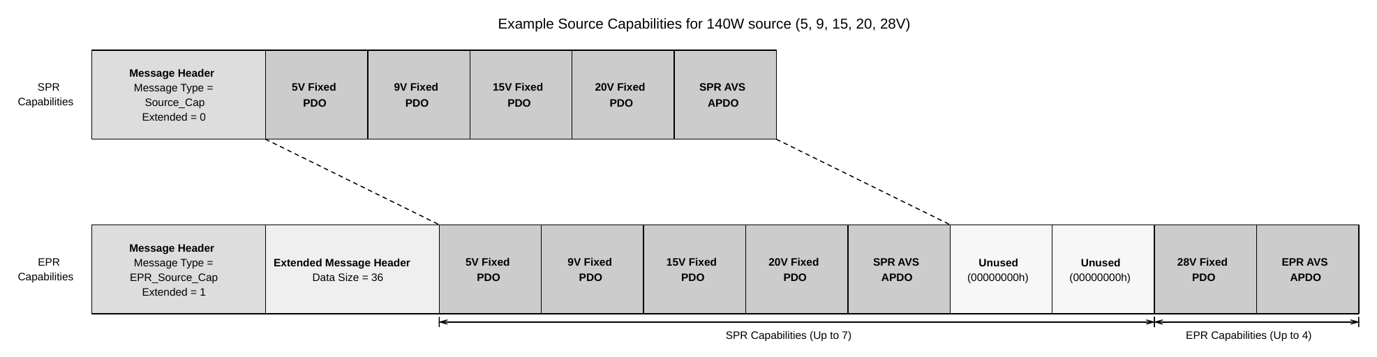
Figure 6.9. Source Capabilities Message Format (with no EPR PDOs)
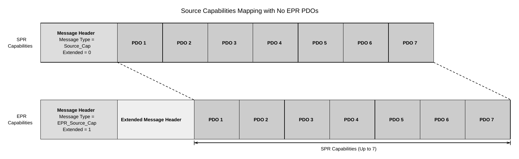
This Message is used in the following sequences:
- EPR Source Capabilities
- EPR Get Source Capabilities
Usage: Section 7.30.2
6.5.19. EPR_Sink_Capabilities Message
The EPR_Sink_Capabilities is an EPR Capabilities Message that contains a list of Power Data Objects that the EPR Sink requires to operate. It is sent by an EPR Sink in order to convey its power requirements to an EPR Source. The EPR Sink Shall only send the EPR_Sink_Capabilities Message in response to an EPR_Get_Sink_Cap Message.
Construction of this Message Shall follow the same rules as EPR_Source_Capabilities Message (see Section 6.5.18).
This Message is used in the following sequences:
- EPR Sink Capabilities
- EPR Get Sink Capabilities
Usage: Section 7.30.4
6.5.20. Vendor_Defined_Extended Message
The Vendor_Defined_Extended Message (VDEM) allows vendors to exchange information outside of the parameters defined by this specification using the Extended Message format.
To ensure vendor uniqueness, all Vendor_Defined_Extended Messages Shall contain a Valid USB Standard or Vendor ID (SVID) that is allocated by USB-IF in the VDM Header.
Table 6.64. Vendor_Defined_Extended Message+
| Byte(s) | Field Name | Static | Description |
|---|---|---|---|
| 1...0 | SVID | No | Standard/Vendor ID (assigned by the USB-IF). |
| 3...2 | Command Space | No | Bit 15: Reserved, Shall be 0bBits 14..0: Vendor Command Data. |
| N...4 | Vendor Defined Data | No | Vendor defined field of 0..256 bytes. |
6.6. Value Parameters
Table 6.65. Value Parameters
| Parameter Name | Min Value | Nom Value | Max Value | Unit | Description |
|---|---|---|---|---|---|
| MaxExtendedMsgLen | 260 | Byte | Maximum length of an Extended Message as expressed in the Data Size field. | ||
| MaxExtendedMsgChunkLen | 26 | Byte | Maximum length of an Extended Message Chunk. | ||
| MaxExtendedMsgLegacyLen | 26 | Byte | Maximum length of an Extended Message that can be sent without Chunking. |