
17 KiB
Chapter 10. Fast Role Swap (FRS)
10.1. Introduction
A Fast Role Swap (FRS) is like a Power Role Swap but is done much faster and without initial Message exchanges to start the Power Role process. FRS is designed for use by charge-through accessories. A Charge-Through Accessory is a USB PD-capable DRP Hub or Device that meets all the following:
- Capable of receiving power from an External Power Supply.
- Capable of receiving power from an upstream Host (e.g., notebook, tablet, phone).
- Capable of supplying power to the upstream Host when powered by an external supply.
- Powers its internal circuitry from whichever power Source is active.
- Capable of powering any downstream ports from whichever power Source is active.
For a Charge-Through Accessory to be an FRS-capable Charge-Through Accessory, it must also meet the following:
- Capable of powering its internal circuitry and downstream ports when receiving 5V from an upstream Host at 15W or less. If higher voltage or more current is required to complete the swap and function, then FRS will not work.
When an FRS-capable Charge-Through Accessory is supplying power to the upstream Host, the loss of the External Supply triggers the FRS mechanism. If the upstream Host also supports and is initialized for FRS, an FRS-capable Charge-Through Accessory will quickly swap power roles with the Host, causing the Host to become the power Source, without disrupting ongoing data connections or Device functionality. This transition relies on temporary internal power storage within the accessory to maintain power within the accessory and continue providing power to any downstream ports during the swap.
FRS ensures power continuity by enabling the Host to apply vSafe5V to VBUS when it detects VBUS drooping
to or below vSafe5V after receiving a valid Fast Role Swap signal. The Fast Role Swap AMS (Atomic Messaging
Sequence) is used in parallel to the power swap on VBUS to reestablish correct Source/Sink power roles and to
properly configure the USB-C Rp/Rd terminations.
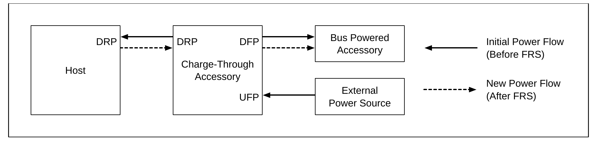
Figure 10.1 shows an example power flow direction before and after an FRS. In this example, an external power Source is powering a Host and a bus-powered accessory through the Charge-Through Accessory. When external power is lost, the FRS event occurs, and the Charge-Through Accessory and the bus-powered accessory are then powered by the Host.
Figure 10.1. Power Flow Before and After an FRS
10.2. FRS Initialization
Prior to an FRS event, the accessory providing power to an upstream Host is the Initial Source and the upstream Host receiving power is the Initial Sink.
The Initial Sink Shall only be initialized for FRS and respond to a Fast Role Swap signal when the following conditions are true:
- An Explicit Contract is established between the Initial Source and the Initial Sink.
- Initial Sink has sent a
Get_Sink_CapMessage and received the Sink Capabilities from the Initial Source with at least one of the Fast Role Swap bits set in the 5V Fixed Supply PDO. - The Initial Sink is capable of sourcing the current (
iNewFrsSnk) indicated by the Initial Source in the Fast Role Swap bits of theSink_CapabilitiesMessage.
Rules for the Initial Sink FRS initialization are:
- The Initial Sink Should check for condition 2 as soon as practical.
- When either condition 1 or 2 is not met, the Initial Sink Shall not initialize for FRS and Shall not respond to an FRS signal.
- When condition 1 or 2 is met but condition 3 is not met, the Initial Sink May initialize for FRS.
- When all three conditions are met, the Initial Sink Should initialize for FRS.
When initialized for FRS, the Initial Sink is ready to respond to an FRS signal. At initialization:
- the Initial Sink Shall disable Type-C disconnect detection and Shall become the VCONN Source if it is required to support VCONN otherwise (i.e., USB 3, DisplayPort Alt Mode, etc.). This avoids requiring a VCONN Swap during the FRS event.
- If the Initial Sink would not be required to Source VCONN as a Source normally (e.g., USB2 only), then it is not required to perform a VCONN Swap.
Note: The Initial Source is unaware whether the Initial Sink is initialized for FRS or not and will attempt to signal FRS on external power loss regardless of the Initial Sink's initialization.
10.3. FRS Sequence
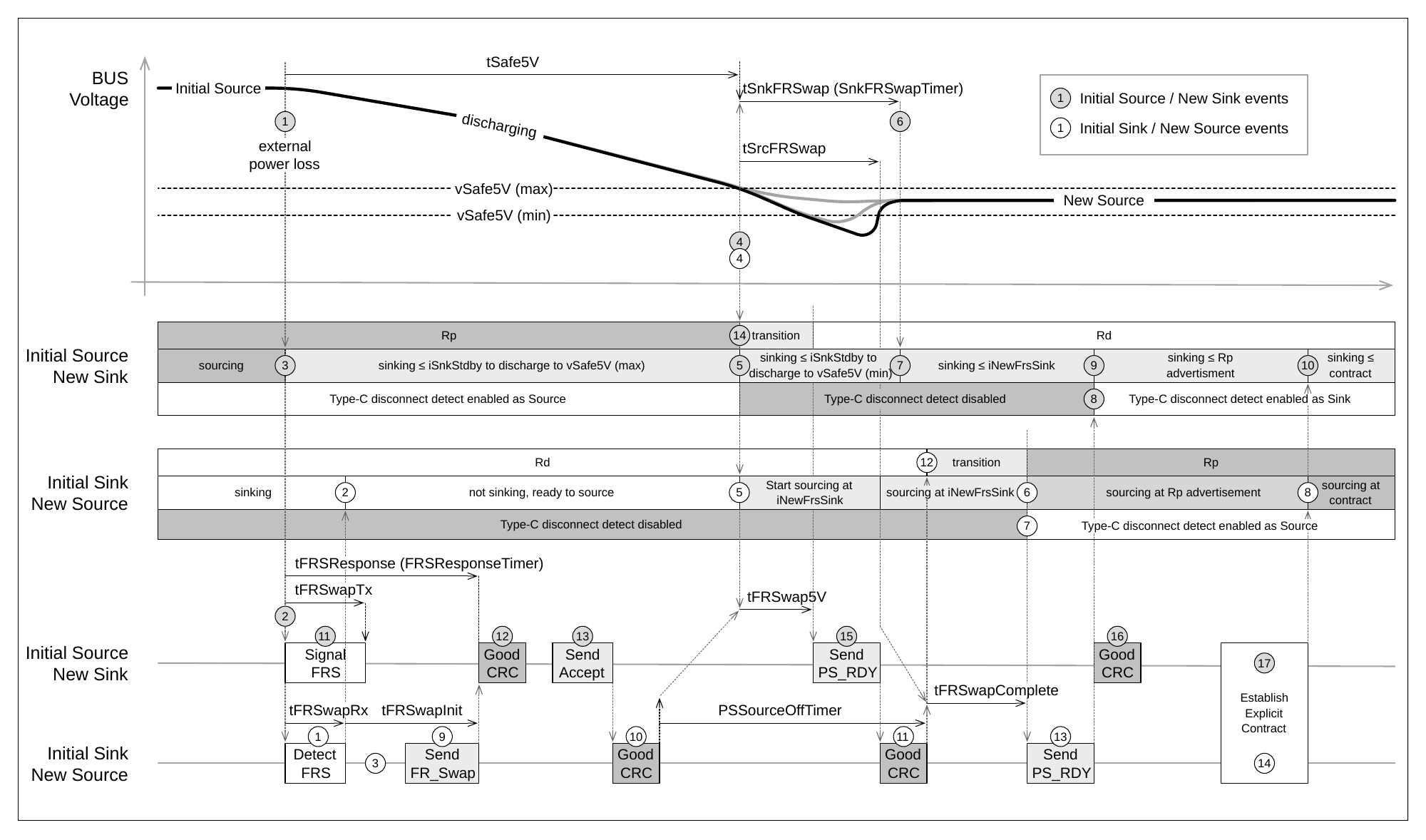
Figure 10.2, Figure 10.3, and Figure 10.4 illustrate the FRS sequence. Figure 10.2 shows the Signaling and response activity diagrams of an FRS. Figure 10.3 and Figure 10.4 show the relative timing diagrams for a slow/long FRS event and a fast/short FRS event. Each figure shows a corresponding numbered event that matches between the activity diagrams, the timing diagrams, and the numbered sequence in the text following the figures.
The Initial Source follows the 'Signal FRS' activity diagram shown in Figure 10.2 when external power loss is detected and the Initial Sink follows the 'FRS Signal Received' activity diagram when it detects the FRS Signal. To swap power quickly, without waiting for Message exchanges, the power activity happens in parallel to, and generally faster than, the messaging on CC. To show this, each activity diagram is broken into swim lanes for Power/Control and CC Signaling and shows both sequential activity paths and parallel paths. Due to the parallel nature of activity, the numbered steps aren't always sequential through the diagram and text.
Figure 10.2. FRS Signaling and Receiving Activity Diagrams
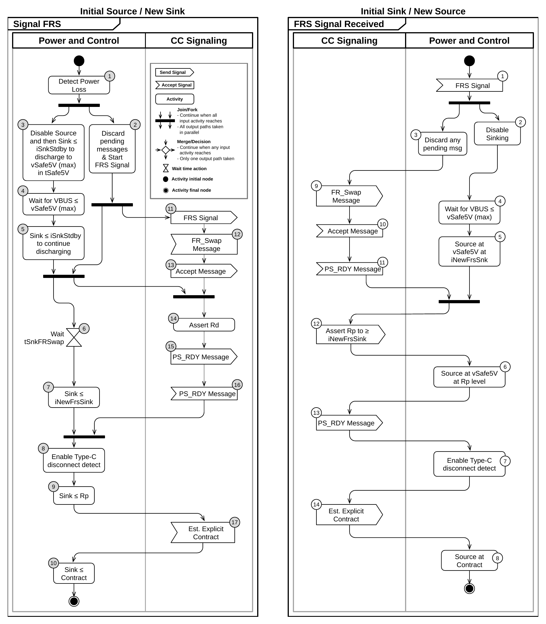
Figure 10.3. FRS Sequence with VBUS Starting at Voltage > vSafe5V (long discharge)
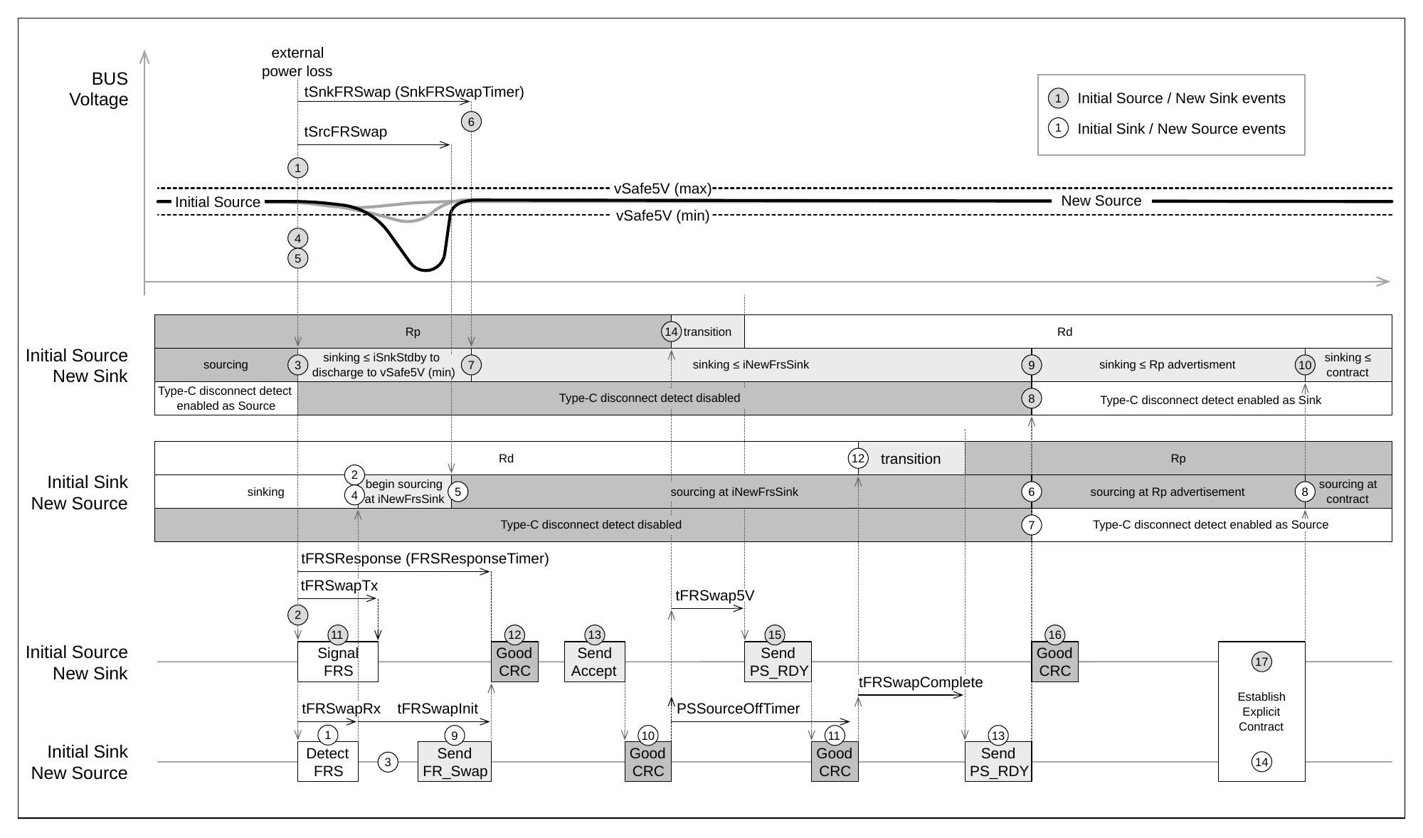
Figure 10.4. FRS Sequence with VBUS starting at vSafe5V (short or no discharge)
10.4. Initial Source/New Sink
An FRS Request is signaled by the Initial Source when it has lost external power and needs the Initial Sink to provide power to VBUS. The Initial Source Should signal the FRS as soon as it is aware that it has lost power. The following steps describe the behavior shown in the 'Signal FRS' activity diagram in Figure 10.2 and the timing diagram shown in Figure 10.3 and Figure 10.4 match the numbers indicated in the figures.
Power and Control
- The Initial Source detects external power loss.
- The Initial Source Shall discard any pending messages and start sending the FRS Signal. The FRS Signal
is transmitted by pulling the CC line below
vFRSwapCableTxfor at leasttFRSwapTx. - At the same time as starting the FRS Signal, the Initial Source Shall stop Sourcing VBUS and Shall start
sinking current ≤
iSnkStdbyfrom VBUS. While VBUS ≥vSafe5V(max), the New Sink Shall Sink enough current to discharge tovSafe5V(max) withintSafe5V. - Wait for VBUS ≤
vSafe5V(max) and initialize theSnkFRSwapTimerwithtSnkFRSwapand start the timer. VBUS may already be ≤vSafe5V(max) when this step is reached. - The New Sink Shall continue to pull current to discharge VBUS to
vSafe5V(min) duringSnkFRSwapTimer. This prevents the process from stalling where the New Source's threshold forvSafe5V(max) might be lower than the New Sink's threshold. The New Source might begin to Source VBUS before reachingvSafe5V(min) resulting in VBUS staying abovevSafe5V(min). If VBUS falls belowvSafe5V(min), the New Sink is no longer required to discharge VBUS. iSnkStdbyis the (max) current that can be drawn untiltSnkFRSwapafter both the FRS Signal was started and VBUS <vSafe5V(max).- After
tSnkFRSwap, the New Sink Shall Sink current ≤iNewFrsSnk.iNewFrsSnkis the current set by the FRS bits in the New Sink's Sink Capabilities initially provided to the Initial Sink. The New Sink Shall Sink current ≤iNewFrsSnkuntil it has detected the New Source's Rp termination. - When the
PS_RDYMessage from the New Source is received, the New Sink is now in an Implicit Contract and Shall enable Type-C disconnect detection. - The New Sink Shall limit the Sink current based on the Implicit Contract until an Explicit Contract is established.
- Once an Explicit Contract is established, normal operation resumes.
CC Signaling
- The FRS Shall be signaled by pulling low on CC for a length
tFRSwapTxand theFRSResponseTimeris initialized withtFRSResponseand started. - After sending the FRS Signal, the Initial Source waits to receive an
FR_SwapMessage. If theFR_SwapMessage is not received and responded to within expiration ofFRSResponseTimer, the New Sink Shall go to errorRecovery. - The New Sink Shall send an
AcceptMessage in response to theFR_SwapMessage withintReceiverResponse. - When both the
GoodCRCMessage response following theAcceptMessage has been received and VBUS ≤vSafe5V(max), the New Sink Shall assert Rd and send aPS_RDYMessage withintFRSwap5V. The Port Power Role field of thePS_RDYMessage Shall be set to Sink. - After sending the
PS_RDY, the New Sink Shall wait for aPS_RDYMessage from the New Source.
- After the
PS_RDYMessage is received from the New Source, the New Sink waits to enter an Explicit Contract with the New Source.
10.4.1. Initial Sink/New Source
An Initial Sink, when initialized for FRS, monitors for the FRS Signal from the Initial Source and disables Type-C disconnect detection via VBUS. The Initial Sink Shall also be ready to Source VBUS as soon as the FRS Signal is received. When the FRS Signal is received, the Initial Sink follows the FRS Signal Received activity diagram shown in Figure 10.2.
Power and Control
- The FRS signal is received by the Initial Sink for at least
tFRSwapRx. - The Initial Sink becomes the New Source and Shall immediately stop sinking current from VBUS.
- At the same time, the New Source Shall discard any pending messages.
- Wait for VBUS ≤
vSafe5V(max) and then proceed. - The New Source Should immediately start sourcing VBUS at
vSafe5VandiNewFrsSnkand Shall start sourcing withintSrcFRSwapof VBUS ≤vSafe5V(min). - When the
PS_RDYMessage from the New Sink is received, the New Source Shall Source VBUS based on the Implicit Contract at a Type-C current ≥iNewFrsSnk. - After sending a
PS_RDYMessage, the New Source Shall enable Type-C disconnect detection. - Once an Explicit Contract is established, normal operation resumes.
CC Signaling
- The New Source responds to the FRS signal by sending the
FR_SwapMessage withintFRSwapInitof completing the detection. - After sending the
FR_SwapMessage, the New Source waits for anAcceptMessage. If theAcceptMessage is not received and responded to with aGoodCRCMessage withintSenderResponsetime, the New Source Shall go to ErrorRecovery. - After receiving the
AcceptMessage, the New Source initalizes thePSSourceOffTimerwithtPSSourceOffand waits to receive aPS_RDYMessage. If thePS_RDYMessage is not received and responded to with aGoodCRCMessage when thePSSourceOffTimerexpires, the New Source Shall go to ErrorRecovery. If the FRS Signal was received while in SPR Mode, the SPRtPSSourceOfftime is used. If the FRS Signal was received while in EPR Mode, the EPRtPSSourceOfftime is used. - After receiving the
PS_RDYMessage and responding with aGoodCRCMessage and VBUS ≤vSafe5V(max), the New Source Shall assert Rp termination for a Type-C current ≥iNewFrsSnk, and send aPS_RDYMessage withintFRSwapCompleteof sending theGoodCRCMessage. The Port Power Role field of thePS_RDYMessage Shall be set to Source. - After sending the
PS_RDYMessage, the New Source Shall establish an Explicit Contract. Note: the New Source May query the Cable Plug with aDiscovery_IdentityMessage prior to sending Source Capabilities.
10.4.2. Constraints During FRS
- The FRS process is considered an AMS. No other messages may be exchanged until all messages in the Fast Role Swap sequences have been completed and an Explicit Contract has been established. If any Unexpected Message is received by either the Source or the Sink, the recipient Shall go to ErrorRecovery.
- If any step in the sequence is missed or delayed, the Initial Source (now New Sink) May run out of internal power and disconnect.
10.5. FRS Parameters
Table 10.1. FRS Timers
| Timer Name | Timer Parameter | Description |
|---|---|---|
FRSResponseTimer |
tFRSResponse |
Timer to enforce tFRSResponse time. |
SnkFRSwapTimer |
tSnkFRSwap |
Timer to enforce tSnkFRSwap time. |
Table 10.2. FRS Parameters
| Parameter Name | Min Value | Nom Value | Max Value | Unit | Description |
|---|---|---|---|---|---|
iNewFrsSink |
Default USB | A | Maximum current the New Sink can draw during a Fast Role Swap until the New Source applies Rp. Matches the required Fast Role Swap required USB Type-C Current field of the Fixed Supply PDO of the Initial Source's Sink_Capabilities Message. |
||
iNewFrsSink |
1.5 | A | Maximum current the New Sink can draw during a Fast Role Swap until the New Source applies Rp. Matches the required Fast Role Swap required USB Type-C Current field of the Fixed Supply PDO of the Initial Source's Sink_Capabilities Message. |
||
iNewFrsSink |
3.0 | A | Maximum current the New Sink can draw during a Fast Role Swap until the New Source applies Rp. Matches the required Fast Role Swap required USB Type-C Current field of the Fixed Supply PDO of the Initial Source's Sink_Capabilities Message. |
||
tFRSResponse |
50 | ms | Interval for the Initial Source to receive an FR_Swap Message from the Initial Sink after sending an FRS Signal.Start: the leading edge of the FRS Signal. End: the last bit of the FR_Swap Message EOP has been transmitted |
||
tFRSwap5V |
15 | ms | Interval for the New Sink to assert Rd and send a PS_RDY Message indicating it has completed the swap from the Initial Source.Start: The later of (both have occurred): • The last bit of the GoodCRC Message response EOP following the Accept Message has been transmitted.• VBUS ≤ vSafe5V.End: the first bit of the PS_RDY Message Preamble has been transmitted. |
||
tFRSwapComplete |
15 | ms | Interval for the New Source to assert Rp and send a PS_RDY Message indicating it has completed the swap from the Initial Sink.Start: The later of (both have occurred): • The last bit of the GoodCRC response EOP following the New Sink's PS_RDY Message has been transmitted.• New Source is sourcing VBUS at vSafe5V.End: first bit of the response PS_RDY Message Preamble has been transmitted. |
||
tFRSwapInit |
15 | ms | Interval for the Initial Sink to send an FR_Swap Message after detecting an FRS Signal.Start: the detection of an FRS signal. End: the last bit of the FR_Swap Message EOP has been transmitted. |
||
tFRSwapRx |
30 | 50 | μs | FRS signal receive duration. Duration of the FRS signal to be detected as valid by the Initial Sink. Start: falling edge of CC low |
|
tFRSwapTx |
60 | 120 | μs | FRS signal transmit duration. Duration of the Initial Source driving CC low to signal an FRS. Start: falling edge of CC low by driving with a resistance to ground of rFRSwapTx.End: rising edge of CC when removing the rFRSwapTx resistance. |
| Parameter Name | Min Value | Nom Value | Max Value | Unit | Description |
|---|---|---|---|---|---|
tSnkFRSwap |
200 | μs | Wait time during an FRS before the New Sink can draw up to iNewFrsSink.Start: The later of (both have occurred): • Start of the FRS signal. • VBUS falling below vSafe5V (min). |
||
tSrcFRSwap |
150 | μs | Interval for the New Source to be actively sourcing VBUS at vSafe5V and iNewFrsSink.Start: VBUS ≤ vSafe5V (max). |
||
rFRSwapTx |
5 | Ω | FRS Signal transmit driver pull-down resistance. Resistance is between the CC pin and ground. | ||
vFRSwapCableTx |
490 | 520 | 550 | mV | FRS Request voltage detection threshold. |