8.7 KiB
4. Typical Performance Graphs
4.1 Battery Charging Only (No BFET)
Figure 7. Adapter Insertion, VADP: 0V → 5V, VBAT = 18V, ChargeCurrent = 0.256A
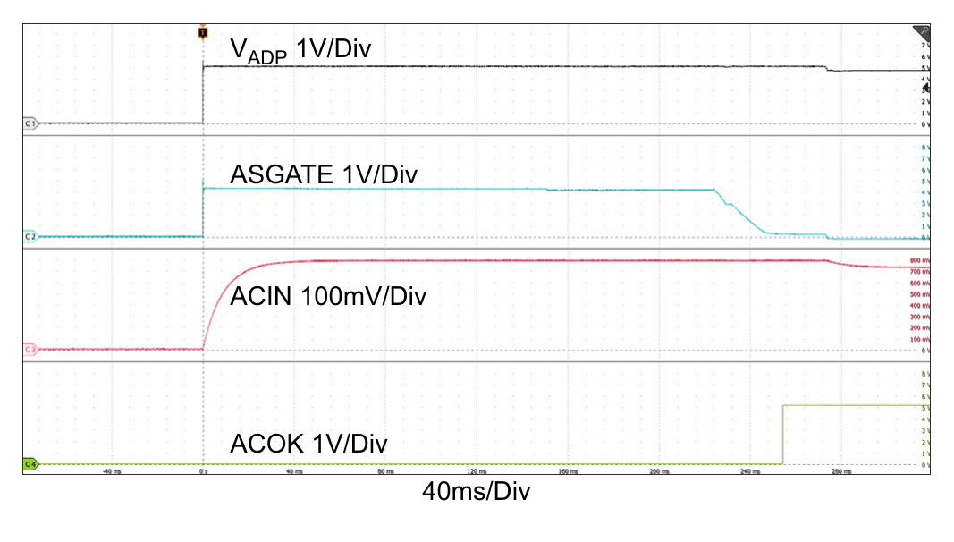
Figure 8. Adapter Insertion, VADP: 0V → 5V, VBAT = 18V, ChargeCurrent = 0.256A (Figure 7 Zoomed In)
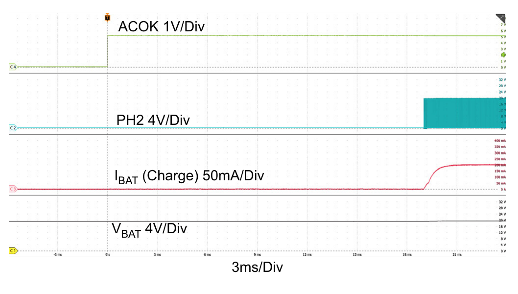
Figure 9. Adapter Removal, VADP: 28V → 0V, VBAT = 18V, ChargeCurrent = 6A
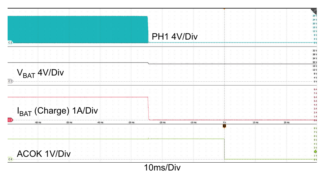
Figure 10. Adapter Voltage Ramp Up, Boost → Buck-Boost → Buck Operation Mode Transitions
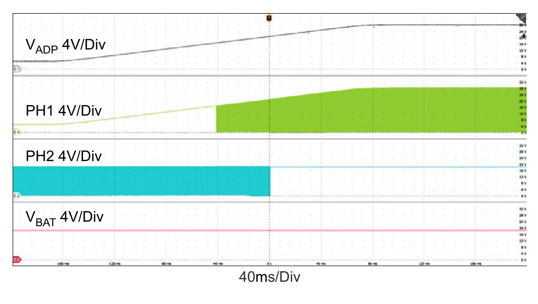
Figure 11. Adapter Voltage Ramp Down, Buck → Buck-Boost → Boost Operation Mode Transitions
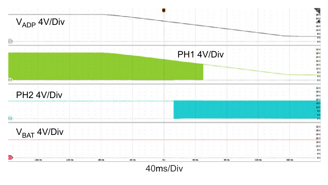
Figure 12. Boost Mode: Charge Current Loop to Adapter Current Loop, VADP = 5V, VBAT = 16V, AdapterCurrentLimit = 3A, ChargeCurrent: 0.5A → 1A
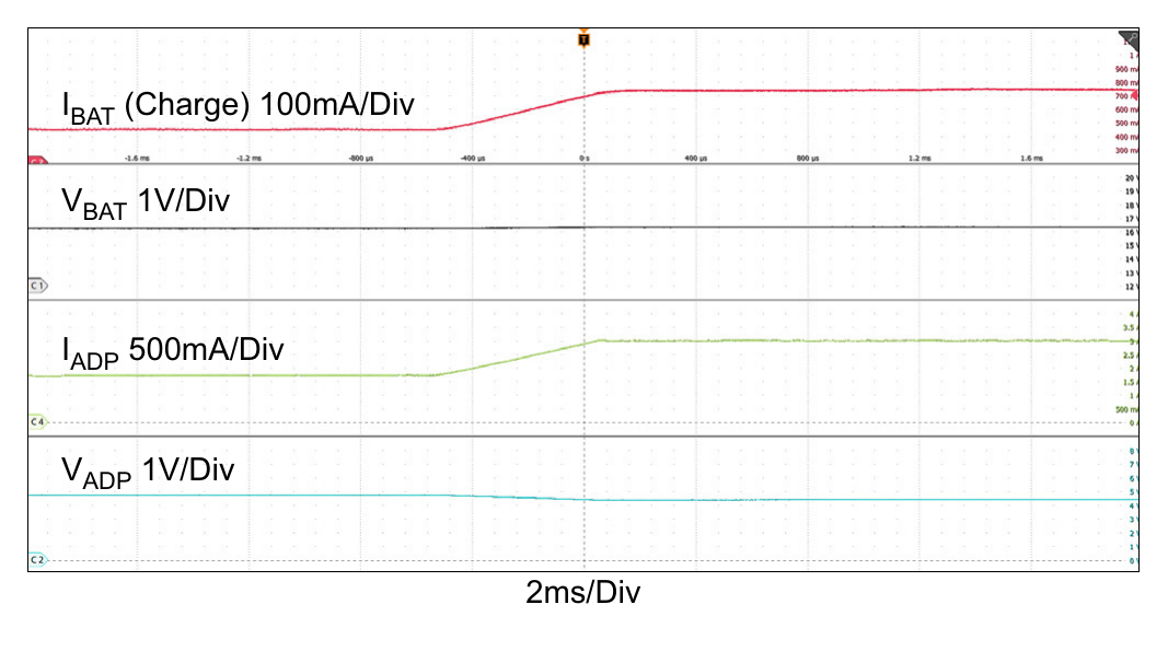
Figure 13. Buck_Boost Mode: Charge Current Loop to Adapter Current Loop, VADP = 20V, VBAT = 19V, AdapterCurrentLimit = 5A, ChargeCurrent: 2A → 6A Buck_Boost_CCM_stretch_period = 2x
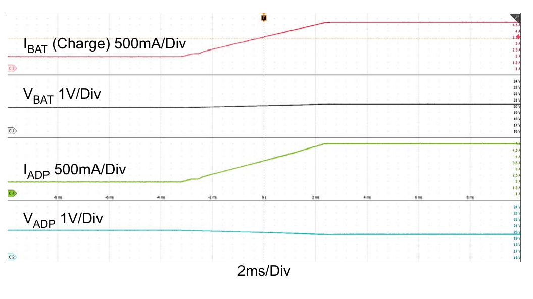
Figure 14. Buck Mode: Charge Current Loop to Adapter Current Loop, VADP = 28V, VBAT = 22V, AdapterCurrentLimit = 5A, ChargeCurrent: 1A → 7A
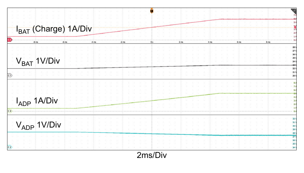
Figure 15. Boost Mode: Charge Current Loop to Input Voltage Loop, VADP = 5V, VBAT = 16V, ChargeCurrent: 0.5A → 2A, InputVoltageLimit = 4.096V
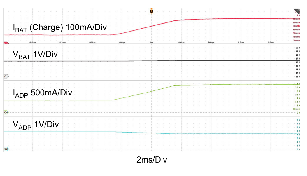
Figure 16. OTG Mode Enable, OTG_Debounce = 150ms, VBAT = 29.4V, VOTG = 20V
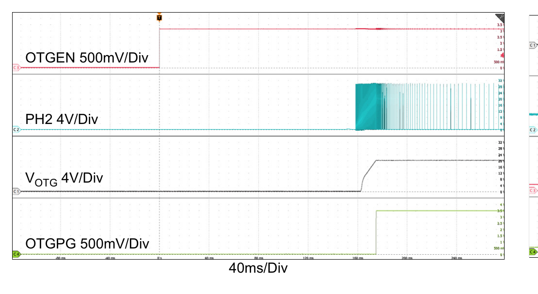
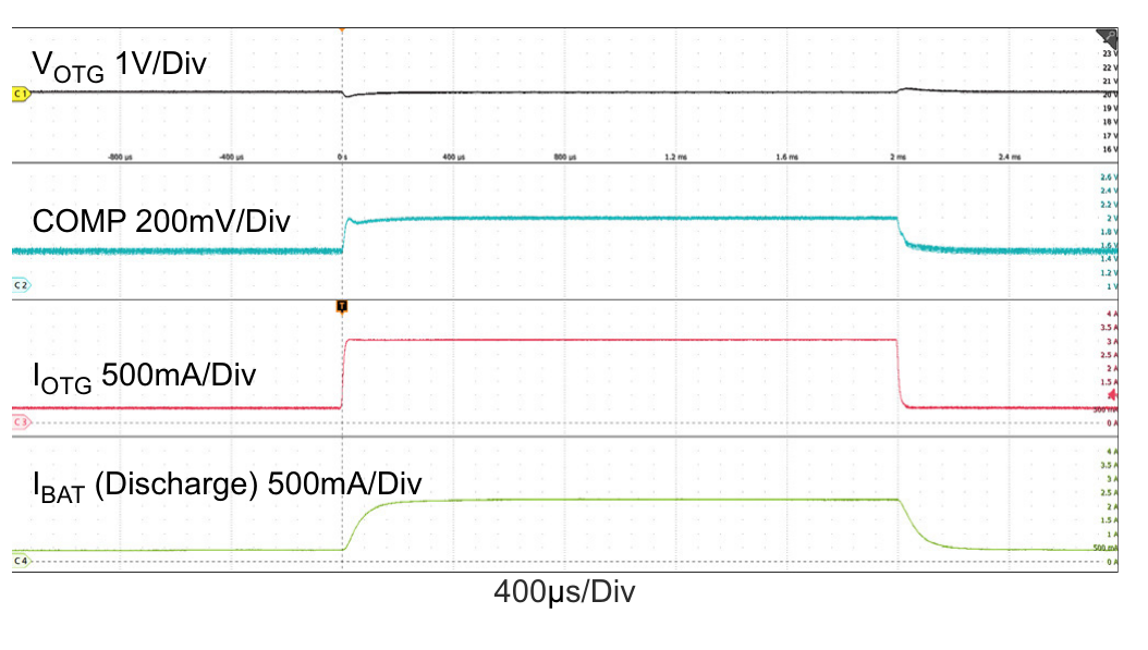
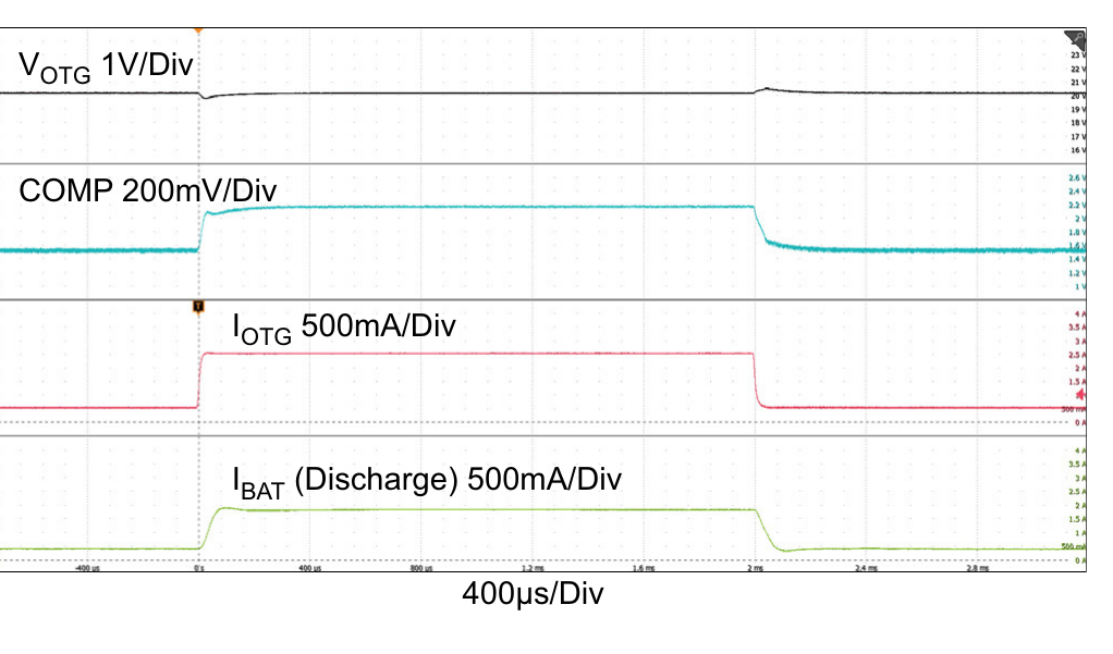
Figure 17. OTG Mode Transients, VBAT = 29.4V, VOTG = 20V, OTG Load: 0.5A ↔ 3A
4.2 NVDC Charging (with BFET)
Figure 18. Adapter Insertion, VADP: 0V → 5V, VBAT = 18V, ChargeCurrent = 0A
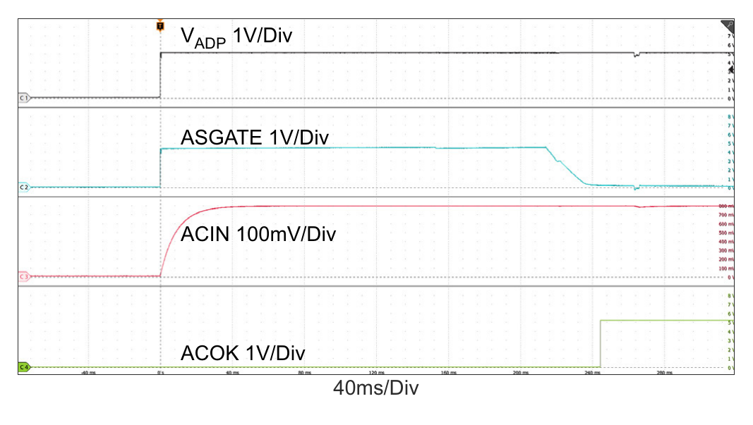
Figure 19. Adapter Insertion, VADP: 0V → 5V, VBAT = 18V, ChargeCurrent = 0A (Figure 18 Zoomed In)
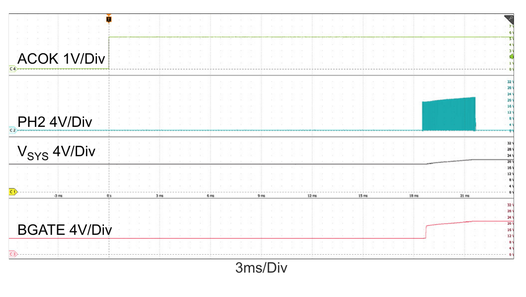
Figure 20. Adapter Removal, VADP: 28V → 0V, VBAT = 18V, SystemLoad = 2A
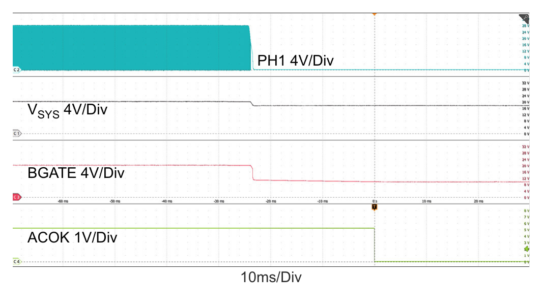
Figure 21. Adapter Voltage Ramp Up, Boost → Buck-Boost → Buck Operation Mode Transitions
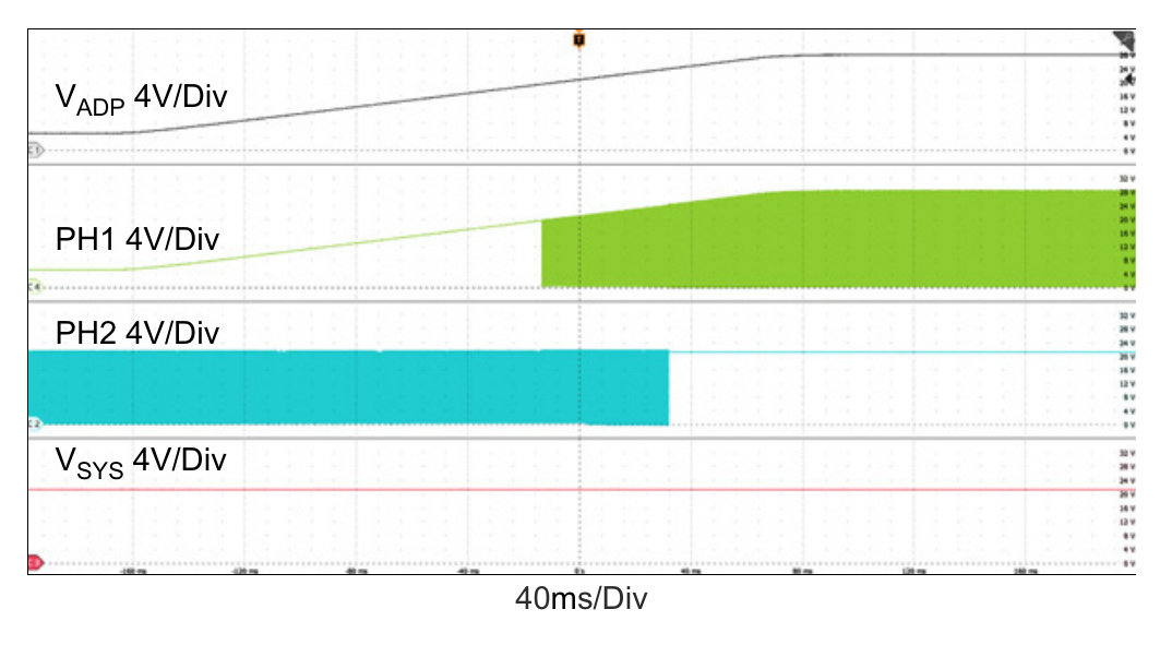
Figure 22. Adapter Voltage Ramp Down, Buck → Buck-Boost → Boost Operation Mode Transitions
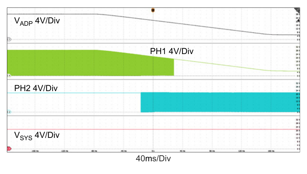
Figure 23. Boost Mode: Output Voltage Loop ↔ Adapter Current Loop, VADP = 5V, MaxSystemVoltage = 21V, VBAT = 20.5V, AdapterCurrentLimit = 3A, ChargeCurrent = 0A, SystemLoad: 0.2A ↔ 4A
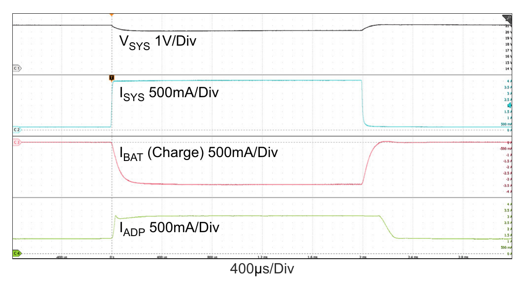
Figure 24. Boost Mode: Charge Current Loop ↔ Adapter Current Loop, VADP = 5V, MaxSystemVoltage = 21V, VBAT = 16V, AdapterCurrentLimit = 3A, ChargeCurrent = 0.5A, SystemLoad: 0A ↔ 4A
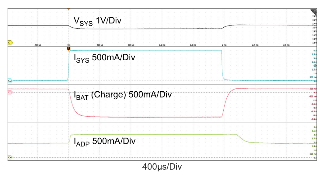
Figure 25. Buck-Boost Mode: Output Voltage Loop ↔ Adapter Current Loop, VADP = 20V, MaxSystemVoltage = 21V, VBAT = 20.5V, AdapterCurrentLimit = 5A, ChargeCurrent = 0A, SystemLoad: 2A ↔ 8A, Buck_Boost_CCM_stretch_period = 2x
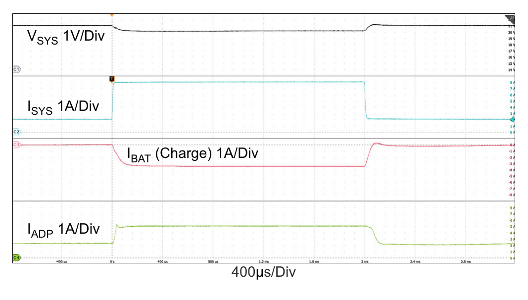
Figure 26. Buck-Boost Mode: Charge Current Loop ↔ Adapter Current Loop, VADP = 20V, MaxSystemVoltage = 21V, VBAT = 20V, AdapterCurrentLimit = 5A, ChargeCurrent = 1A, SystemLoad: 2A ↔ 8A, Buck_Boost_CCM_stretch_period = 2x
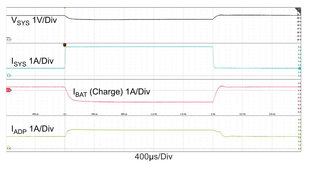
Figure 27. Buck Mode: Output Voltage Loop ↔ Adapter Current Loop, VADP = 28V, MaxSystemVoltage = 21V, VBAT = 20.5V, AdapterCurrentLimit = 5A, ChargeCurrent = 0A, SystemLoad: 2A ↔ 12A
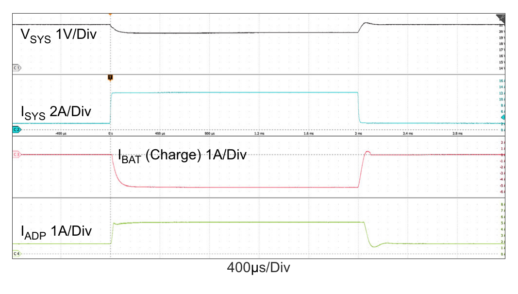
Figure 28. Buck Mode: Charge Current Loop ↔ Adapter Current Loop, VADP = 28V, MaxSystemVoltage = 21V, VBAT = 20V, AdapterCurrentLimit = 5A, ChargeCurrent = 1A, SystemLoad: 2A ↔ 12A
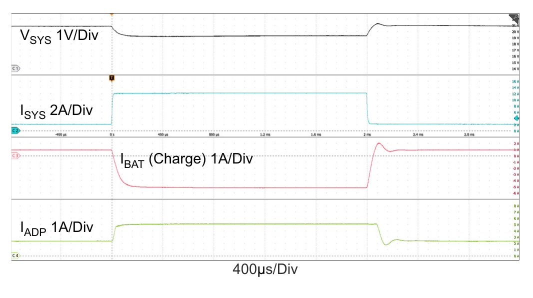
Figure 29. Boost Mode: Output Voltage Loop ↔ Input Voltage Loop, VADP = 5V, MaxSystemVoltage = 21V, VBAT = 20.5V, InputVoltageLimit = 4.096V, ChargeCurrent = 0A, SystemLoad: 0A ↔ 4A
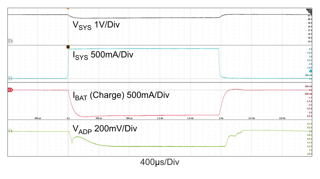
Figure 30. Boost Mode: Charge Current Loop ↔ Input Voltage Loop, VADP = 5V, MaxSysVoltage = 21V, VBAT = 16V, InputVoltageLimit = 4.096V, ChargeCurrent = 0.5A, SystemLoad: 0A ↔ 4A
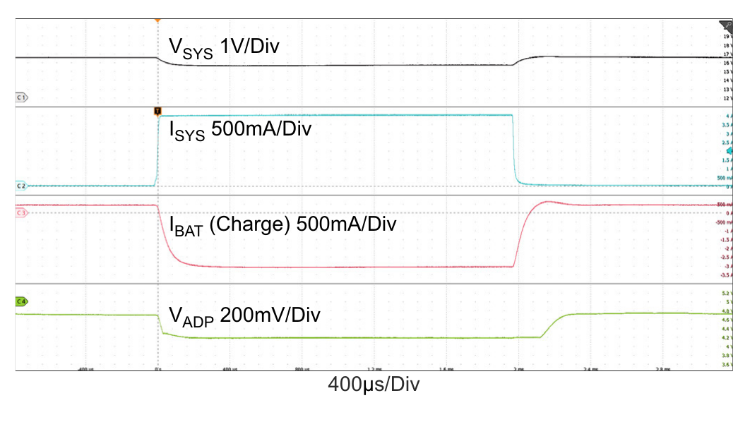
Figure 31. OTG Mode Enable. OTG_Debounce = 150ms, VBAT = 29.4V, VOTG = 20V
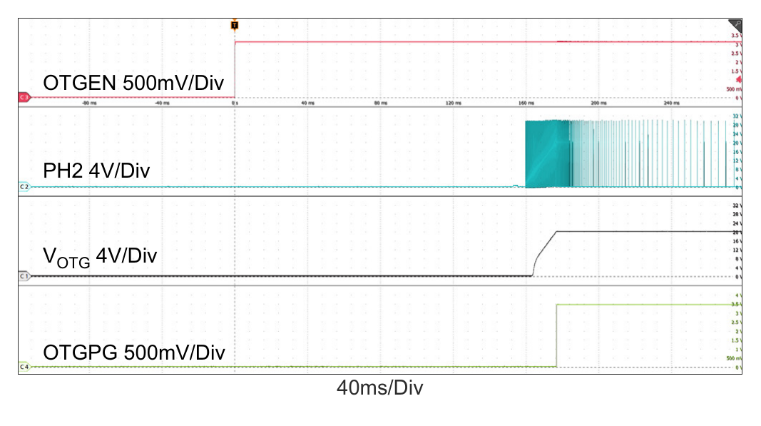
Figure 32. OTG Mode Transients. VBAT = 29.4V, VOTG = 20V, OTG Current = 5A, OTG Load: 0.5A ↔ 3A