
126 KiB
Chapter 7. PD Communications Protocol Message Usage
7.1. Reset
Resets are a necessary response to protocol or other error conditions. USB Power Delivery defines four different types of reset:
- Soft Reset, which resets protocol.
- Data Reset, which resets the USB communications.
- Hard Reset, which resets both the power supplies and protocol.
- Cable Reset which resets the cable.
7.1.1. Soft Reset and Protocol Error
A Soft_Reset Message is used to cause a Soft Reset of the communication protocol when it has broken down in some way. The breakdown in communication or the Protocol Error may take several forms:
- An Unexpected Message is received during an AMS.
- An expected Message fails to arrive.
- A timeout occurs while waiting for a Message or event.
The Soft Reset Shall Not have any impact on power supply operation but is used to correct a Protocol Error occurring during an Atomic Message Sequence (AMS). After a Soft Reset has completed, an Explicit Contract Negotiation occurs, in order to re-establish PD Communication and to bring State operation for both Port Partners back to either the PE_SNK_Ready or PE_SRC_Ready states as appropriate (see Section 9.2.5). The Soft Reset May be triggered by either Port Partner in response to the Protocol Error. An Accept Message is sent by the recipient of a Soft Reset Message to indicate that it has completed the Soft Reset.
The Protocol Error may result in:
- a Hard Reset.
- a Soft Reset.
- or no response.
An Unrecognized Message or Unsupported Message received in a Protocol Engine ready State causes a Not_Supported Message to be generated.
If the error is not corrected by the Soft Reset, Hard Reset Signaling Shall be issued (see Section 7.1.3).
A Soft Reset may be sent by either the Source or Sink in response to a Protocol Error irrespective of the value of Rp, either SinkTxOK or SinkTxNG. If the Soft_Reset Message fails a Hard Reset Shall be initiated within tHardReset of the last CRCReceiveTimer expiring after nRetryCount retries have been completed.
A Soft_Reset Message Shall be targeted at a specific entity depending on the type of SOP* Packet used. Soft_Reset Messages sent using SOP Packets Shall Soft Reset the Port Partner only. Soft_Reset Messages sent using SOP' Packet/ SOP'' Packets Shall Soft Reset the corresponding Cable Plug only.
After a VCONN Swap the VCONN Source needs to reset the Cable Plug's Protocol Layer to ensure MessageID synchronization. If after a VCONN Swap the VCONN Source wants to communicate with a Cable Plug using SOP'
Packets, it Shall issue a Soft_Reset Message using a SOP' Packet in order to reset the Cable Plug's Protocol Layer. If the VCONN Source wants to communicate with a Cable Plug using SOP'' Packets, it Shall issue a Soft_Reset Message using a SOP'' Packet in order to reset the Cable Plug's Protocol Layer.
See Section 9.2, "Policy Engine Layer State Diagrams" for more details.
Table 7.1 and Table 7.2 summarize the responses that Shall be made to an incoming Message including VDMs.
Table 7.1. Response to an incoming Message (except VDM)
| Recipient's Power Role | Recipient's State | Recognized / Supported / Expected | Recognized / Supported / Unexpected | Recognized / Unsupported | Unrecognized |
|---|---|---|---|---|---|
| Source | PE_SRC_Ready | Process Message | Soft_Reset Message1 | Not_Supported Message2 | Not_Supported Message2 (except for VDM) See Section 8.4 for UVDM. See Section 8.5 for SVDM |
| Source | During AMS (power not transitioning3) | Process Message | Soft_Reset Message1 | Soft_Reset Message1 | Soft_Reset Message1 |
| Source | During AMS (power transitioning3) | Process Message | Hard Reset Signaling | Hard Reset Signaling | Hard Reset Signaling |
| Sink | PE_SNK_Ready | Process Message | Soft_Reset Message1 | Not_Supported Message2 | Not_Supported Message2 (except for VDM) See Section 8.4 for UVDM. See Section 8.5 for SVDM |
| Sink | During AMS (not power transitioned) | Process Message | Soft_Reset Message1 | Soft_Reset Message1 | Soft_Reset Message1 |
| Sink | During AMS (power transitioned) | Process Message | Hard Reset Signaling | Hard Reset Signaling | Hard Reset Signaling |
Table 7.2. Response to an incoming VDM
| Recipient's Role | Unstructured VDM: Supported | Unstructured VDM: Unsupported | Unstructured VDM: Unrecognized | Structured VDM: Supported | Structured VDM: Unsupported | Structured VDM: Unrecognized |
|---|---|---|---|---|---|---|
| DFP or UFP | Defined by vendor | Not_Supported Message | Not_Supported Message | See: Table 7.4 | Not_Supported Message | NAK Command |
| Cable Plug | Defined by vendor | Message Ignored | Message Ignored | See: Table 7.5 | Message Ignored | NAK Command |
A failure to see a GoodCRC Message in response to any Message within tReceive (after nRetryCount retries), when a Port Pair is Connected, is indicative of a communications failure resulting in a Soft Reset (see Section 7.1.1).
A Soft Reset Shall impact the USB Power Delivery layers in the following ways:
- PHY Layer: Reset not required since the PHY Layer resets on each Packet transmission/reception.
- Protocol Layer: Reset MessageIDCounter, RetryCounter and State machines.
- Policy Engine: Reset State dependent behavior by performing an Explicit Contract Negotiation.
- Power supply: Does not change.
Note: When in SPR Mode the Source sends a Source_Capabilities Message and when in EPR Mode the Source sends an EPR_Source_Capabilities Message.
A Soft Reset is performed using an AMS (see Section 7.7).
7.1.2. Data Reset
The Data_Reset Message May be sent by either the DFP or UFP and Shall reset the USB data connection and exit all Alternate Modes with its Port Partner while preserving the power on VBUS. USB4 Mode capable ports Shall support the Data_Reset Message and other ports May support the Data_Reset Message.
The Data_Reset Message Shall Not change the existing:
- Power Contract
- Data Roles (i.e., which Port is the DFP or UFP)
The receiver of the Data_Reset Message Shall respond by sending an Accept Message and then follow the process outlined in the following steps. Neither the sender nor receiver Shall initiate a VCONN Swap until the Data Reset process is complete, and the Data_Reset_Complete Message has been sent. Following receipt of the Accept Message, or GoodCRC Message following the Accept Message, depending which Port sends the Data_Reset Message:
- The DFP Shall:
- Disconnect the Port's [USB2] D+/D- signals.
- If operating in [USB3] remove the Port's Rx Terminations (see [USB3]).
- If operating in [USB4] drive the Port's SBTX to a logic low (see [USB4]).
- Both the DFP and UFP Shall exit all Alternate Modes if any.
- Reset the cable:
- If the VCONN Source Port is also the UFP, then it Shall run the UFP VCONN Power Cycle process described in Section 4.6.
- If the VCONN Source Port is also the DFP, then it Shall run the DFP VCONN Power Cycle process described in Section 4.6.
- The DFP Shall exit the VCONN Power Cycle process as the VCONN Source and be sourcing VCONN.
- After tDataReset the DFP Shall:
- Reconnect the [USB2] D+/D- signals.
- If the Port was operating in [USB3] or [USB4] reapply the Port's Rx Terminations (see [USB3]).
- The Data Reset process is complete; the DFP Shall send a Data_Reset_Complete Message and enter the USB4 Discovery and Entry Flow (See [USB-C]).
If the Initiator of the Data_Reset Message does not receive a Valid response within tSenderResponse it Shall enter the ErrorRecovery State.
7.1.3. Hard Reset
Hard Resets are signaled by an ordered set as defined in Table 5.4. Both the sender and recipient Shall cause their power supplies to return to their default states (see Figure 4.14 for details of voltage transitions). In addition, their respective Protocol Layers Shall be reset as for the Soft Reset. This allows the Attached devices to be in a State
where they can re-establish USB PD communication. Hard Reset is retried up to nHardResetCount times (see also Section 7.31.5.4 and Section 7.32.5).
Note: Even though VBUS drops to vSafe0V during a Hard Reset a Sink will not see this as a disconnect since this is expected behavior.
A Hard Reset Shall Not cause any change to either the Rp/Rd resistor being asserted.
If there has been a Data Role Swap the Hard Reset Shall cause the Port Data Role to be changed back to DFP for a Port with the Rp resistor asserted and UFP for a Port with the Rd resistor asserted.
When VCONN is supported (see [USB-C]) the Hard Reset Shall cause the Port with the Rp resistor asserted to supply VCONN and the Port with the Rd resistor asserted to turn off VCONN.
If the Hard Reset is insufficient to clear the error condition, then the Port Shall use USB Type-C ErrorRecovery as defined in [USB-C].
A Sink Shall be able to send Hard Reset Signaling regardless of the value of Rp (see Section 5.2.2").
7.1.3.1. Cable Plugs and Hard Reset
Cable Plugs Shall Not generate Hard Reset Signaling but Shall monitor for Hard Reset Signaling between the Port Partners and Shall reset when this is detected (see Section 9.2.26.2.2). The Cable Plugs Shall perform the equivalent of a power cycle returning to their initial power up State. This allows the Port Partners to be in a State where they can re-establish USB PD communication.
7.1.3.2. Modal Operation and Hard Reset
A Hard Reset Shall cause EPR Mode and all Active Modes to be exited by both Port Partners and any Cable Plugs (see Section 8.6.4").
7.1.4. Cable Reset
Cable Resets are signaled by an ordered set as defined in Table 5.4. Both the sender and recipient of Cable Reset Signaling Shall reset their respective Protocol Layers. The Cable Plugs Shall perform the equivalent of a power cycle returning to their initial power up State. This allows the Port Partners to be in a State where they can reestablish USB PD communication.
Only a DFP Shall generate Cable Reset Signaling. The DFP must be supplying VCONN prior to a Cable Reset. If VCONN has been turned off the DFP Shall turn on VCONN prior to generating Cable Reset Signaling. If there has been a VCONN Swap and the UFP is currently supplying VCONN, the DFP Shall perform a VCONN Swap such that it is supplying VCONN prior to generating Cable Reset Signaling. A DFP Shall only generate Cable Reset Signaling within an Explicit Contract.
A Cable Reset Shall cause all Active Modes in the Cable Plugs to be exited (see Section 8.6.4").
7.2. Collision Avoidance
To avoid Message collisions due to asynchronous Messaging sent from the Sink, the Source sets Rp to SinkTxOK to indicate to the Sink that it is OK to initiate an AMS. When the Source wishes to initiate an AMS, it sets Rp to SinkTxNG. When the Sink detects that Rp is set to SinkTxOK it May initiate an AMS. When the Sink detects that Rp is set to SinkTxNG it Shall Not initiate an AMS once tSinkDelay has elapsed after SinkTxNG is asserted, and Shall only send Messages that are part of a Source-initiated AMS.
Note: This restriction applies to SOP* AMSs i.e., for both Port to Port and Port to Cable Plug communications.
Note: A Sink can still send Hard Reset Signaling at any time.
7.3. Message Discarding
On receiving a received Message on SOP, the Protocol Layer Shall Discard any pending SOP* Messages. A received Message on SOP'/SOP'' Shall Not cause any pending SOP* Messages to be Discarded.
It is assumed that Messages using SOP'/SOP'' constitute a simple Request/response AMS, with the Cable Plug providing the response so there is no reason for a pending SOP* Message to be Discarded. There can only be one AMS between the Port Partners, and these also take priority over Cable Plug communications so a Message received on SOP will always cause a Message pending on SOP* to be Discarded.
Table 7.3 for details of the Messages that Shall/ Shall Not be Discarded.
Table 7.3. Message Discarding
| Message pending transmission | Message received | Message to be Discarded |
|---|---|---|
| SOP | SOP | Outgoing Message |
| SOP | SOP'/SOP'' | Incoming Message |
| SOP' | SOP | Outgoing Message |
| SOP' | SOP' | Incoming Message |
| SOP' | SOP'' | Incoming Message |
| SOP'' | SOP | Outgoing Message |
| SOP'' | SOP' | Incoming Message |
| SOP'' | SOP'' | Incoming Message |
7.4. Common Messages
7.4.1. Accept
Usage details for the Accept Message are given in each of the different AMS sequences where it is used.
7.4.2. Reject
Most usage details for the Reject Message are given in each of the different AMS sequences where it is used.
The sender of a Request, EPR_Request Message, PR_Swap Message, DR_Swap Message, VCONN_Swap, or Enter_USB Message, on receiving a Reject Message response, Shall Not send this same Message to the recipient until one of the following has occurred:
- A New Explicit Contract Negotiation as a result of the Source sending a Source_Capabilities Message or EPR_Source_Capabilities Message. This can be triggered by:
- The Source's Device Policy Manager.
- A Get_Source_Cap Message sent from the Sink to the Source in SPR Mode.
- An EPR_Get_Source_Cap Message sent from the Sink to the Source in EPR Mode.
- A Power Role Swap.
- A Soft Reset.
- A Hard Reset.
- A Disconnect/Re-Connect.
- A Data Role Swap.
- A Data Reset.
7.4.3. Wait
Usage details for the Wait Message are given in each of the different AMS sequences where it is used.
7.5. Applicability Tables
Table 7.4 and Table 7.5 lists the AMS and Message requirements for a Port/Cable Plug.
The "Initiator Applicability" column refers to a Port's requirement to be able to start an AMS, while the "Responder Applicability" column refers to a Port's requirement to respond to an AMS. The "Transmitter" column specifies the transmitter of that specific Message in the sequence. The Initiator of an AMS is the transmitter of the first Message in that sequence. Ports May initiate or respond to any AMS not explicitly forbidden.
When multiple messages are allowed in an AMS (e.g. Accept/Reject/Wait), transmitters May choose to not implement all of the options. Receivers Shall be able to understand any of the Message options.
See Chapter 9 for detailed State diagrams explaining the AMS and messaging options.
Table 7.4. Port Sequence Applicability
| AMS | Initiator Applicability | Responder Applicability | General Message Sequence | Transmitter |
|---|---|---|---|---|
| Source Capabilities | Required for ports that can operate as Source | Required | Source_Capabilities |
Source |
Request |
Sink | |||
| Accept/Reject/Wait | Source | |||
PS_RDY |
Source | |||
| Request | Required for ports that can operate as Sink | Required | Request |
Sink |
| Accept/Reject/Wait | Source | |||
PS_RDY |
Source | |||
| EPR Source Capabilities | Required for ports that can operate as EPR Source | Required for EPR Capable ports | EPR_Source_Capabilities |
Source |
EPR_Request |
Sink | |||
| Accept/Reject/Wait | Source | |||
PS_RDY |
Source | |||
| EPR Request | Required for ports that can operate as EPR Sink | Required for EPR Capable ports | EPR_Request |
Sink |
| Accept/Reject/Wait | Source | |||
PS_RDY |
Source | |||
| EPR Mode Enter | Required for ports that can operate as EPR Sink | Required for EPR Capable ports | EPR_Mode (Enter) |
Sink |
EPR_Mode (Enter Acknowledge) |
Source | |||
| VCONN Swap Sequence | - | |||
| Cable Plug Discover Identity (SVDM) Sequence | - | |||
EPR_Mode (Enter Succeeded/Enter Failed) |
Source | |||
| EPR Source Capabilties Sequence | - | |||
| EPR Keep Alive | Required for ports that can operate as EPR Sink | Required for EPR Capable ports | EPR_Keep_Alive |
Sink |
EPR_Keep_Alive_Ack |
Source | |||
| EPR Mode Exit | Recommended for EPR Capable ports | Required for EPR Capable ports | EPR_Mode (Exit) |
Any |
| Source Capabilities Sequence | - | |||
| Unsupported Sequence | Required | Initiating Message | Any | |
Not_Supported |
Any |
| AMS | Initiator Applicability | Responder Applicability | General Message Sequence | Transmitter |
|---|---|---|---|---|
| Soft Reset | Required | Required | Soft_Reset |
Any |
| Accept | Responder | |||
| Source Capabilities/EPR Source Capabilities Sequence | - | |||
| Data Reset | Required for USB4 capable ports | Required for USB4 capable ports | Data_Reset |
Any |
| Accept | Responder | |||
PS_RDY |
UFP VCONN Source | |||
Data_Reset_Complete |
DFP | |||
| Power Role Swap | Required for DRP Unsupported by Source only/Sink only |
Required for DRP | PR_Swap |
Any |
| Accept/Reject/Wait | Responder | |||
PS_RDY |
Initial Source | |||
PS_RDY |
New Source | |||
| Fast Role Swap | Recommended for DRP Unsupported by Source only/Sink only |
Optional for DRP | FR_Swap |
Sink |
| Accept | Source | |||
PS_RDY |
Initial Source | |||
PS_RDY |
New Source | |||
| Data Role Swap | Required for DRD | Required for DRD | DR_Swap |
Any |
| Accept/Reject/Wait | Responder | |||
| VCONN_Swap | Recommended | Required for ports that can supply VCONN | VCONN_Swap |
Any |
| Accept/Reject/Wait | Responder | |||
PS_RDY |
New VCONN Source | |||
| Alert | Required for ports that support SPR PPS Mode | Recommended | Alert | Any |
| Optional Get Status Sequence | - | |||
| Optional Get Battery Status Sequence | - | |||
| Get Status | Recommended | Required for Source ports that support Alert | Get_Status |
Any |
| Status | Responder | |||
| Get PPS Status | Required for ports that support SPR PPS Mode | Required for ports that support SPR PPS Mode | Get_PPS_Status |
PPS Sink |
PPS_Status |
PPS Source | |||
| Get Source Capabilities | Recommended for ports that can operate as Sink | Required for ports that can operate as Source | Get_Source_Cap |
Any |
Source_Capabilities |
Responder | |||
| If in SPR Mode and AMS was initiated by the Sink: Request Sequence | - | |||
| Get Sink Capabilities | Recommended for ports that can operate as Source | Required for ports that can operate as Sink | Get_Sink_Cap |
Any |
Sink_Capabilities |
Responder | |||
| EPR Get Source Capabilities | Recommended for ports that can operate as EPR Sink | Required for ports that can operate as EPR Source | EPR_Get_Source_Cap |
Any |
EPR_Source_Capabilities/Reject |
Responder | |||
| If in EPR Mode and AMS was initiated by the Sink: EPR Request Sequence | - | |||
| EPR Get Sink Capabilities | Recommended for ports that can operate as EPR Source | Required for ports that can operate as EPR Sink | EPR_Get_Sink_Cap |
Any |
EPR_Sink_Capabilities/Reject |
Responder |
| AMS | Initiator Applicability | Responder Applicability | General Message Sequence | Transmitter |
|---|---|---|---|---|
| Get Source Capabilities Extended | Recommended for ports that can operate as Sink | Recommended for ports that can operate as Source | Get_Source_Cap_Extended |
Any |
Source_Capabilities_Extended |
Responder | |||
| Get Sink Capabilities Extended | Recommended for ports that can operate as Source | Required for ports that can operate as Sink | Get_Sink_Cap_Extended |
Any |
Sink_Capabilities_Extended |
Responder | |||
| Get Battery Capabilities | Recommended | Required if product contains batteries | Get_Battery_Cap |
Any |
Battery_Capabilities |
Responder | |||
| Get Battery Status | Recommended | Required if product contains batteries | Get_Battery_Status |
Any |
Battery_Status |
Responder | |||
| Get Manufacturer Info | Recommended | Recommended | Get_Manufacturer_Info |
Any |
Manufacturer_Info |
Responder | |||
| Get Country Codes | Required if mandated by a country authority | Required if mandated by a country authority | Get_Country_Codes |
Any |
Country_Codes |
Responder | |||
| Get Country Info | Required if mandated by a country authority | Required if mandated by a country authority | Get_Country_Info |
Any |
Country_Info |
Responder | |||
| Get Revision | Recommended | Required | Get_Revision |
Any |
| Revision | Responder | |||
| Get Source Information | Recommended for ports that can operate as Sink | Required for ports that can operate as Source (except single Port SPR Chargers with Invariant PDOs) | Get_Source_Info |
Any |
Source_Info |
Responder | |||
| Security Request | Required by ports that support USB security communication as defined in [USBC Auth]. | Required by ports that support USB security communication as defined in [USBC Auth]. | Security_Request |
Any |
Security_Response |
Responder | |||
| Firmware Update Request | Required by ports that support USB firmware update communication as defined in [USB DFU]. | Required by ports that support USB firmware update communication as defined in [USB DFU]. | Firmware_Update_Request |
Any |
Firmware_Update_Response |
Responder | |||
| Discover Identity (SVDM) | Recommended for ports that can operate as Source | Required for USB4 capable ports, products with more than one DFP, or ports that support Modal Operation | Discover Identity Vendor_Defined INIT | Any |
| Discover Identity Vendor_Defined ACK/NAK/BUSY | Responder | |||
| Discover SVIDs (SVDM) | Required for ports that support Modal Operation | Required for ports that support Modal Operation | Discover SVIDs Vendor_Defined INIT | Any |
| Discover SVIDs Vendor_Defined ACK/NAK/BUSY | Responder | |||
| Discover Modes (SVDM) | Required for ports that support Modal Operation | Required for ports that support Modal Operation | Discover Modes Vendor_Defined INIT | Any |
| Discover Modes Vendor_Defined ACK/NAK/BUSY | Responder | |||
| Enter Mode (SVDM) | Required for ports that support Modal Operation | Required for ports that support Modal Operation | Enter Mode Vendor_Defined INIT | DFP |
| Enter Mode Vendor_Defined ACK/NAK/BUSY | UFP | |||
| Exit Mode (SVDM) | Required for ports that support Modal Operation | Required for ports that support Modal Operation | Exit Mode Vendor_Defined INIT | DFP |
| Exit Mode Vendor_Defined ACK/NAK/BUSY | UFP | |||
| Structured VDM (Other) | Optional | Optional | Vendor_Defined INIT | Any |
| Vendor_Defined ACK/NAK/BUSY | Responder |
| AMS | Initiator Applicability | Responder Applicability | General Message Sequence | Transmitter |
|---|---|---|---|---|
| Enter USB | Required for USB4 capable ports | Required for USB4 capable ports | Enter_USB |
DFP |
| Accept/Reject/Wait | UFP |
Table 7.5 applies to all Cable Plugs and to any Ports that are otherwise required to communicate with the Cable Plug. Only Ports acting as a VCONN Source are allowed to initiate AMSs listed in this table. The Port is always the Initiator of amy AMS to the Cable Plug. For a port that is not currently the VCONN Source to communicate with the Cable Plug, initiate the VCONN Swap AMS to become the VCONN Source.
Cable Plugs May respond to any AMS not explicitly forbidden.
Table 7.5. Cable Plug Sequence Applicability
| AMS | Port Initiator Applicability | SOP' Responder Applicability | SOP'' Responder Applicability | Message Sequence | Transmitter |
|---|---|---|---|---|---|
| Unsupported Sequence | Required | Required | Initiating Message | Port (VCONN Source) | |
Not_Supported |
Cable | ||||
| Soft Reset | Required | Required | Required | Soft_Reset |
Port (VCONN Source) |
| Accept | Cable | ||||
| Get Status | Optional | Required for Active Cables | Required for Active Cables | Get_Status |
Port (VCONN Source) |
| Status | Cable | ||||
| Get Manufacturer Info | Optional | Recommended | Not Allowed | Get_Manufacturer_Info |
Port (VCONN Source) |
Manufacturer_Info |
Cable | ||||
| Get Revision | Optional | Required for Active Cables | Not Allowed | Get_Revision |
Port (VCONN Source) |
| Revision | Cable | ||||
| Security Request | Required by ports that support USB security communication as defined in [USBC Auth]. | Required by cables that support USB security communication as defined in [USBC Auth]. | Not Allowed | Security_Request |
Port (VCONN Source) |
Security_Response |
Cable | ||||
| Firmware Update Request | Required by ports that support USB firmware update communication as defined in [USB DFU]. | Required by cables that support USB firmware update communication as defined in [USB DFU]. | Optional | Firmware_Update_Request |
Port (VCONN Source) |
Firmware_Update_Response |
Cable | ||||
| Discover Identity (SVDM) | Required for ports that can operate as Source and offer >3A. Required for ports that support Modal Operation. Required for USB4 capable ports. Recommended for all ports. |
Required | Not Allowed | Discover Identity Vendor_Defined INIT | Port (VCONN Source) |
| Discover Identity Vendor_Defined ACK/NAK/BUSY | Cable |
| AMS | Port Initiator Applicability | SOP' Responder Applicability | SOP'' Responder Applicability | Message Sequence | Transmitter |
|---|---|---|---|---|---|
| Discover SVIDs (SVDM) | Required for ports that support Modal Operation. | Required, responds NAK if Modal Operation is not supported | Not Allowed | Discover SVIDs Vendor_Defined INIT | Port (VCONN Source) |
| Discover SVIDs Vendor_Defined ACK/NAK/BUSY | Cable | ||||
| Discover Modes (SVDM) | Required for ports that support Modal Operation. | Required, responds NAK if Modal Operation is not supported | Not Allowed | Discover Modes Vendor_Defined INIT | Port (VCONN Source) |
| Discover Modes Vendor_Defined ACK/NAK/BUSY | Cable | ||||
| Enter Mode (SVDM) | Required for ports that support Modal Operation. | Required, responds NAK if Modal Operation is not supported | Optional | Enter Mode Vendor_Defined INIT | Port (VCONN Source) |
| Enter Mode Vendor_Defined ACK/NAK/BUSY | Cable | ||||
| Exit Mode (SVDM) | Required for ports that support Modal Operation. | Required, responds NAK if Modal Operation is not supported | Optional | Exit Mode Vendor_Defined INIT | Port (VCONN Source) |
| Exit Mode Vendor_Defined ACK/NAK/BUSY | Cable | ||||
| Structured VDM (Other) | Optional | Optional | Optional | Vendor_Defined INIT | Port (VCONN Source) |
| Vendor_Defined ACK/NAK/BUSY | Cable | ||||
| Enter USB | Required for USB4 capable ports. | Required for Active Cables that support USB4 | Required for Active Cables that support USB4 | Enter_USB |
Port (VCONN Source) |
| Accept/Reject/Wait | Cable |
Table 7.6 and Table 7.7 cover messages that may not be a part of an AMS, but still have applicability for given ports/cable plugs.
Table 7.6. Port Message Applicability
| Message | Transmit Applicability | Receive Applicability |
|---|---|---|
GoodCRC |
Required | Required |
| Attention (SVDM) | Optional | Optional |
| Vendor_Defined (Unstructured) | Optional | Optional |
Vendor_Defined_Extended |
Optional | Optional |
| BIST | Required | Required |
Hard_Reset |
Required | Required |
Table 7.7. Cable Plug Message Applicability
| Message | Transmit Applicability | Receive Applicability |
|---|---|---|
GoodCRC |
Required | Required |
| Attention (SVDM) | Not Allowed | Ignore |
| Vendor_Defined (Unstructured) | Optional | Optional |
Vendor_Defined_Extended |
Optional | Optional |
| BIST | Not Allowed | Required |
Hard_Reset |
Not Allowed | Required |
Cable_Reset |
Not Allowed | Required |
7.6. AMS Usages
7.6.1. Basic Message Exchange
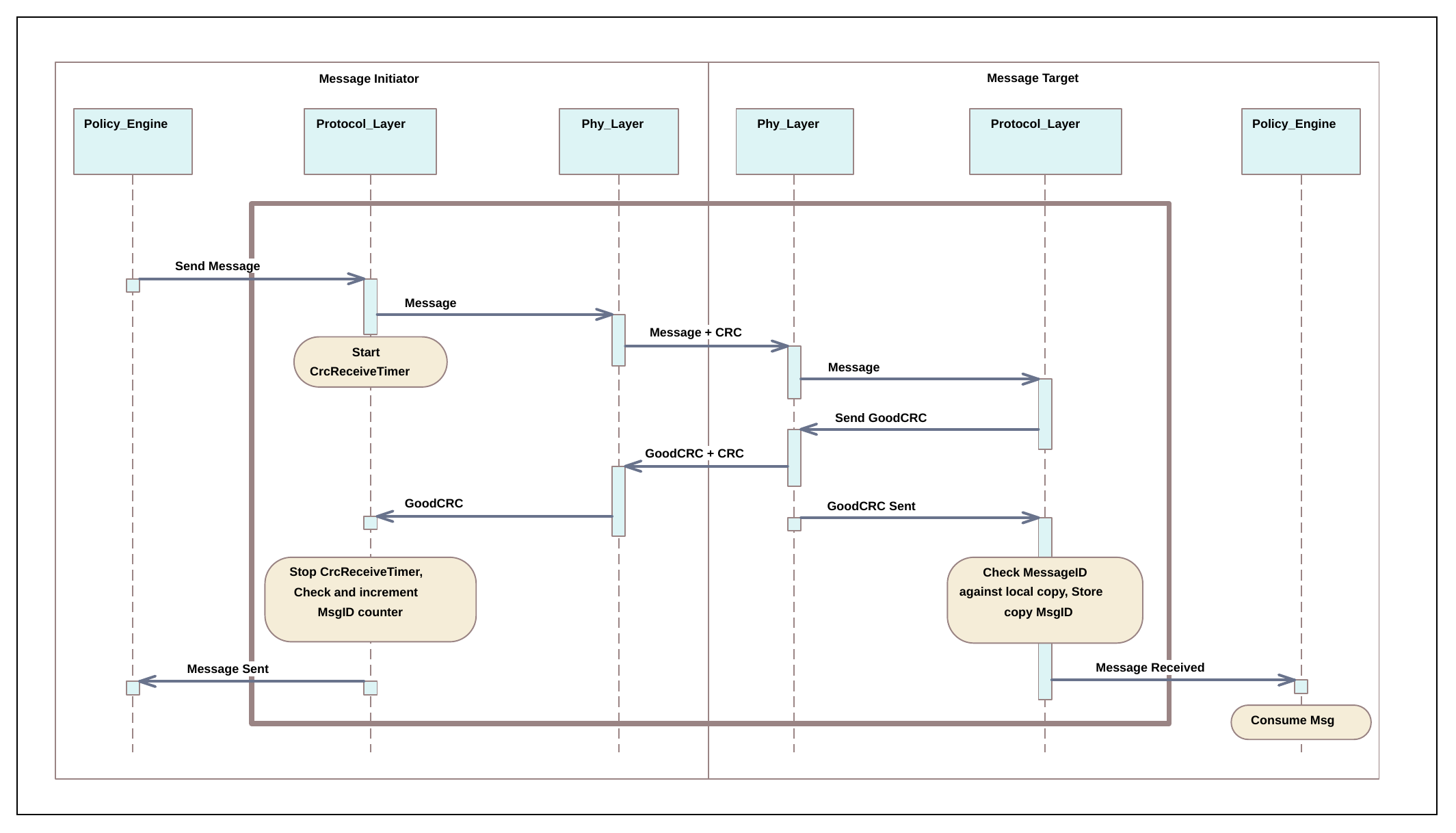
Figure 7.1 illustrates how a Message is sent. Note: The sender might be either a Source or Sink while the receiver might be either a Sink or Source. The basic Message sequence is the same. It starts when the Message Initiator's Policy Engine forms a Message that it passes to the Protocol Layer. The "Protocol to protocol core" sequence fragment defines where:
- the Message Request arrives at the Initiator Protocol Layer on the left side,
- the Request is delivered to the target Policy Engine on the right side, and
- the Message-sent event is delivered to the Initiator Protocol Layer on the left side.
This fragment is used in subsequent diagrams when the Message flow through the protocol and physical layers are identical.
Figure 7.1. Sequence diagram of messaging core between protocol layers
7.6.2. Possible Points of Failure for Message Delivery
There are various points during the Message flow where failures in communication or other issues can occur. Figure 7.2 below is an annotated Version of Figure 7.1 indicating at which points issues can occur.
Figure 7.2. Basic Message flow indicating possible errors
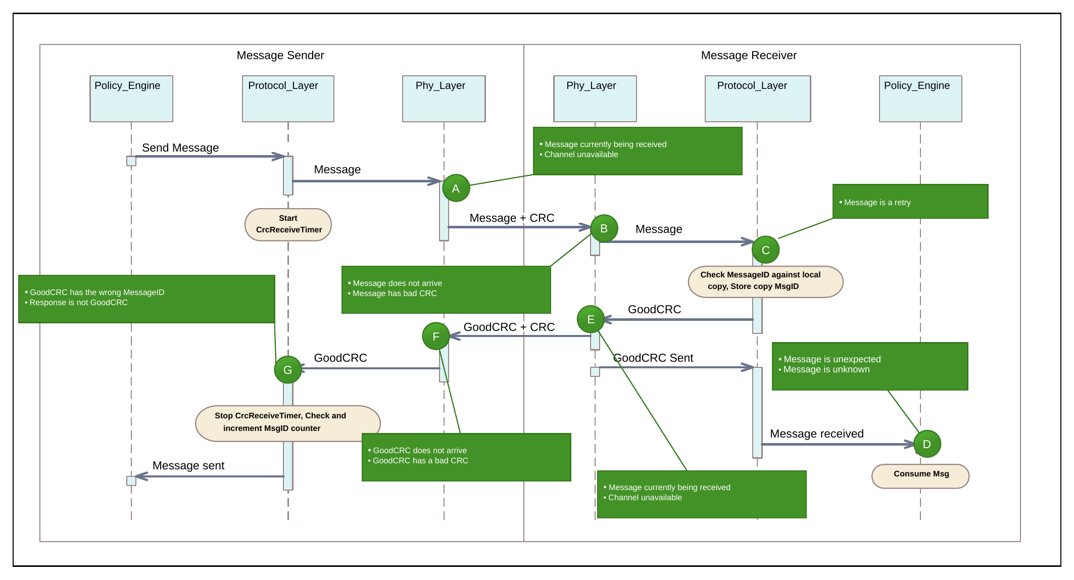
Table 7.8. Potential Issues in the Basic Message Flow
| Point | Possible Issues |
|---|---|
| A | 1. There is an incoming Message on the channel, meaning that the PHY Layer is unable to send. In this case the outgoing Message is removed from the queue and the incoming Message processed. 2. Due to some sort of noise on the line it is not possible to transmit. In this case the outgoing Message is Discarded by the PHY Layer. Retransmission is via the Protocol Layer's normal mechanism. |
| B | 1. Message does not arrive at the PHY Layer due to noise on the channel. 2. Message arrives but has been corrupted and has a bad CRC. There is no Message to pass up to the Protocol Layer on the receiver which means a GoodCRC Message is not sent. This leads to a CRCReceiveTimer timeout in the Message Sender. |
| C | Same as Point A, but at the Message Receiver side. |
| D | 1. GoodCRC Message response does not arrive at the Message Sender side due to the noise on the channel. 2. GoodCRC Message response arrives but has a bad CRC. A GoodCRC Message is not received by the Message Sender's Protocol Layer. This leads to a CRCReceiveTimertimeout in the Message Sender. |
| E | MessageID of received Message matches stored MessageID so this is a retry. Message is not passed up to the Policy Engine. |
| F | 1. GoodCRC Message is received but does contain the same MessageID as the transmitted Message. 2. A Message is received but it is not a GoodCRC Message (similar case to that of an unexpected or unknown Message but this time detected in the Protocol Layer). Both of these issues indicate errors in receiving an expected GoodCRC Message which will lead to a CRCReceiveTimer timeout in the Protocol Layer and a subsequent retry (except for communications with Cable Plugs). |
| G | 1. Policy Engine receives a known Message that it was not expecting. 2. Policy Engine receives an Unrecognized Message. These cases are errors in the protocol which could lead to the generation of a Soft_Reset Message. |
7.7. Soft Reset AMS
Message numbers Shall be set to zero prior to sending the Soft_Reset/Accept Message since the issue might be with the counters. The sender of a Soft_Reset Message Shall reset its MessageIDCounter and RetryCounter to 0. The receiver of the Message Shall reset its MessageIDCounter and RetryCounter to 0 before sending the Accept Message response. A Port Partner observing a Protocol Error during an SOP Soft Reset Shall initiate a Hard Reset; a DFP observing a Protocol Error during an SOP'/SOP'' Soft Reset Shall initiate a Cable Reset (see Section 7.1.3 and Section 7.1.4).
7.8. Data Reset AMS
In a Data Reset AMS, the Initiator sends a Data_Reset Message. The Responder will respond with an Accept Message. Both Port partners will then follow the process given in Section 7.1.2, "Data Reset". When the Data Reset process is complete, the DFP will complete the AMS by sending a Data_Reset_Complete Message to the UFP regardless of the role of the Initiator.
7.9. Power Negotiation (SPR) AMS
7.9.1. Source_Capabililties Message
7.9.1.1. Power Data Objects
Section 6.4.1.1 and Section 6.4.1.3 describe the Power Data Objects (PDOs) used in the construction of a Capabilities Message for both SPR Mode and EPR Mode.
Power Data Objects are also used to expose additional Capabilities that May be utilized, such as in the case of a Power Role Swap.
A list of one or more Power Data Objects Shall be sent by the Source to convey its Capabilities. The Sink May then Request one of these Capabilities by returning a Request Data Object that contains an index to a Power Data Object, to Negotiate a mutually agreeable Explicit Contract.
Where Maximum and Minimum voltage and current values are given in PDOs these Shall be taken to be absolute values.
The Source and Sink Shall Not Negotiate a power level that would allow the current to exceed the maximum current supported by their receptacles or the Attached plug (see [USB-C]). The Source Shall limit its offered Capabilities to the maximum current supported by its receptacle and Attached plug. A Sink Shall only make a Request from any of the Capabilities offered by the Source. For further details see Section 8.6.1.2.2.
Sources expose their power Capabilities by sending a Source_Capabilities Message. Sinks expose their power requirements by sending a Sink_Capabilities Message. Both are composed of several 32-bit Power Data Objects (see Section 7.9.1.1).
The Augmented Power Data Object (APDO) is defined to allow support for more than the four PDO types by extending the Power Data Object field from 2 to 4 bits when the B31…B30 are 11b. The generic APDO structure is shown in Table 6.7"
7.9.1.2. USB Suspend Supported
Prior to an Explicit Contract or when the USB Communications Capable bit is set to zero, the USB Suspend Supported flag is undefined and Sinks Shall follow the rules for suspend as defined in [USB2], [USB 3.2], [USB4], [USBC] or [USB BC]. After an Explicit Contract has been Negotiated:
- A PDUSB Peripheral May draw up to
pSnkSuspduring suspend; a PDUSB Hub May draw up topHubSuspduring suspend (see Section 4.2.3").
Note: When USB is suspended, the USB Device State is also suspended.
Sinks May indicate to the Source that they would prefer to have the USB Suspend Supported flag cleared by setting the No USB Suspend flag in a Request Message (see Section 6.4.2.1.8).
7.9.1.3. Unconstrained Power
To set the Unconstrained Power bit because of an external Source, the external Source of power Should be either:
- An AC Supply, e.g., a Charger, directly Connected to the Sink.
- Or, in the case of a PDUSB Hub:
- A PD Source with its Unconstrained Power bit set.
- Multiple PD Sources all with their Unconstrained Power bits set.
7.9.1.4. EPR Mode Capable
When this bit is set, an EPR Source:
- Operating in SPR Mode Shall only send an
EPR_Source_CapabilitiesMessage in response to anEPR_Get_Source_CapMessage
7.9.1.5. Source Offering No Capabilities
A Source offering no Capabilities (0mA or 0W) Shall offer a single Fixed Supply PDO with Voltage set to 5V and Maximum Current set to 0mA. Examples of products that might do this:
- A Dual-Role Power product that offers no Capabilities as a Source or in the absence of external power.
- A Source that wants the Sink to draw no more than
pSnkSusp. - A Sink with Accessory Support that does not support VBUS but is sourcing VCONN to an Accessory (see [USB-C]).
7.9.2. Request Message
A Request Message Shall be sent by a Sink to Request power during the Request phase of an SPR power Negotiation. The Request Data Object Shall be returned by the Sink making a Request for power. It Shall be sent in response to the most recent Source_Capabilities Message when in SPR Mode.
The Request Message includes the requested power level. For example, if the Source_Capabilities Message includes a Fixed Supply PDO that offers 9V @ 1.5A and if the Sink only wants 9V @ 0.5A, it will set the Operating Current field to 50 (i.e., 10mA * 50 = 0.5A).
Note: A Source in AVS Mode, unlike the SPR Source in PPS Mode, does not support Current Limit; the Sink is responsible not to take more current than it requested.
The Accept Message Shall be sent by the Source, in SPR Mode, to signal the Sink that the Source is willing to meet the Request Message.
The Reject Message Shall be sent to signal the Sink, in SPR Mode, that the Source is unable to meet the Request Message. This May be due an Invalid Request or because the Source can no longer provide what it previously Advertised.
A Source operating in EPR Mode that receives a Request Message Shall initiate a Hard Reset.
The Sink May send a different Request Message to the one which was rejected but Shall Not repeat the same Request Message, using the same RDO, unless there has been a New Explicit Contract Negotiation, Data Role Swap, or Data Reset.
7.9.2.1. Capability Mismatch
Capabilities Mismatch occurs when the Source cannot satisfy the Sink's power requirements based on the offered Source Capabilities. In this case the Sink Shall make a Valid Request from the offered Source Capabilities and Shall set the Capability Mismatch bit. When a Capabilities Mismatch condition does not exist, the Sink Shall Not set the Capability Mismatch bit.
When a Sink returns a Request Data Object with the Capability Mismatch bit set in response to a Source Capabilities Message, it indicates that it wants more power than the Source is currently offering. This can be due to a lack of a specific offered voltage or insufficient current for the offered voltages.
Sources whose Port Reported PDP is less than their Port Present PDP (see Section 6.4.10) Shall respond to Requests with the Capability Mismatch bit set by issuing a New Source Capabilities Message within tCapabilitiesMismatchResponse of the PS_RDY Message that offers either:
-
The set of Source Capabilities to minimally satisfy the Sink's requirements based on what it actually requires for full operation by evaluating the:
i.
Sink_Capabilities_ExtendedMessage (for Sinks > PD2) and/orii.
Sink_CapabilitiesMessage orEPR_Sink_CapabilitiesMessage. -
The set of Source Capabilities the Source can supply at this time based on the Port Present PDP.
To prevent looping, Sources Should Not send a New Source Capabilities Message in response to subsequent Request Message with the Capability Mismatch flag set until its Port Present PDP changes.
Once a Guaranteed Capability Source that has responded to a Capability Mismatch, it Shall Not subsequently send out another Source Capabilities Message at a lower PDP unless the power required by the Sink (as indicated in its Sink Capabilities Message) has also been reduced. Sources wishing to manage their power May periodically check the Sink Capabilities Message to determine whether this has changed.
Note: A Source Capabilities Message refers to a Source_Capabilities Message or an EPR_Source_Capabilities Message, and a Sink Capabilities Message refers to a Sink_Capabilities Message or EPR_Sink_Capabilities Message, Request refers to a Request Message or EPR_Request Message depending on operating Mode.
7.9.2.2. Wait in Response to Request Message
The Wait Message allows the Source time to recover the power it requires to meet the Request, e.g., through Re-Negotiation with other Sinks or an upstream Source. A Source Should only send a Wait Message in response to a Request Message when an Explicit Contract exists between the Port Partners. The Sink is allowed to repeat the Request Message using the SinkRequestTimer and Shall ensure that at least tSinkRequest has elapsed after receiving the Wait Message before sending another Request Message.
7.9.3. PS_Rdy
The PS_RDY Message Shall be sent by the Source (or by both the New Sink and New Source during the Power Role Swap AMS or Fast Role Swap AMS) to indicate its power supply has reached the desired operating condition.
7.10. Power Role Swap AMS
The PR_Swap Message May be sent by either Port Partner to Request an exchange of Power Roles. The recipient of the Message Shall respond by sending an Accept Message, a Wait Message or a Reject Message.
- The Accept Message Shall be sent by the recipient of the
PR_SwapMessage to signal that it is willing to do a Power Role Swap and has begun the Power Role Swap AMS. If an Accept Message is sent, the Source and Sink Shall do a Power Role Swap. - The Reject Message Shall be sent by the recipient of the
PR_SwapMessage to signal that it is unable or unwilling to do a Power Role Swap. If a Reject Message is sent, no action Shall be taken. - For a Wait Message, see section, Section 7.10.1
The PR_Swap Message Shall Not be sent while in EPR Mode. While in EPR Mode if a Power Role Swap is required, an EPR Mode Exit Shall be done first. After a successful Power Role Swap the Port Partners Shall reset their respective Protocol Layers (equivalent to a Soft Reset): resetting their MessageIDCounter, RetryCounter and Protocol Layer State machines before attempting to establish the First Explicit Contract. At this point the New Source Shall also reset its CapsCounter.
The New Source Shall have Rp asserted on the CC wire and the New Sink Shall have Rd asserted on the CC wire as defined in [USB-C]. When performing a Power Role Swap from Source to Sink, the Port Shall change its CC wire resistor from Rp to Rd. When performing a Power Role Swap from Sink to Source, the Port Shall change its CC wire resistor from Rd to Rp. The DFP (Host), UFP (Device) Data Roles and VCONN Source Shall remain unchanged by the Power Role Swap process.
During the Power Role Swap AMS, for the Initial Source Port, the Port Power Role field Shall be set to Sink in the PS_RDY Message indicating that the Initial Source's power supply is turned off.
During the Power Role Swap AMS, for the Initial Sink, the Port Power Role field Shall be set to Source for Messages initiated by the Policy Engine after receiving the PS_RDY Message from the Initial Source.
Note: During the Power Role Swap process the Initial Sink does not disconnect even though VBUS drops below vSafe5V.
For more information regarding the Power Role Swap, refer to:
Section 4.3.3, "Power Role Swap Sequence"
Section 7.1.2, "Data Reset".
Section 9.2.20.3, "Policy Engine in Source to Sink Power Role Swap State Diagram"
Section 9.2.20.4, "Policy Engine in Sink to Source Power Role Swap State Diagram"
7.10.1. Wait in response to a PR_Swap Message
The Wait Message is used when responding to a PR_Swap Message to indicate that a Power Role Swap might be possible in the future. This can occur in any case where the Device receiving the PR_Swap Message needs to evaluate the Request further e.g., by requesting Sink Capabilities from the originator of the PR_Swap Message. Once it has completed this evaluation one of the Port Partners Should initiate the Power Role Swap process again by sending a PR_Swap Message. Once it has completed this evaluation one of the Port Partners Should initiate the Power Role Swap process again by sending a PR_Swap Message.
The Wait Message is also used where a Hub is operating in hybrid Mode when a Request cannot be satisfied (see [UCSI]). A Port that receives a Wait Message in response to a PR_Swap Message Shall wait tPRSwapWait after receiving the Wait Message before sending another PR_Swap Message.
7.11. Fast Role Swap AMS
See Chapter 10 for details regarding Fast Role Swap.
7.12. Data Role Swap AMS
7.12.1. DR_Swap
The Data Role Swap process can be used by Port Partners whether or not they support USB Communications capability. A DFP that supports USB Communication capability starts as the USB Host on Attachment. A UFP that supports USB Communication capability starts as the USB Device on Attachment.
[USB-C] Dual-Role Data (DRD) Ports Shall have the capability to perform a Data Role Swap from the PE_SRC_Ready or PE_SNK_Ready states. DFPs and UFPs May have the capability to perform a Data Role Swap from the PE_SRC_Ready or PE_SNK_Ready states. A Data Role Swap Shall be regarded in the same way as a cable Detach/Re-Attach in relation to any USB Communication which is ongoing between the Port Partners. If there are any Active Modes between the Port Partners when a DR_Swap Message is a received, then a Hard Reset Shall be
performed (see Section 8.6.4"). If the Cable Plug has any Active Modes then the DFP Shall Not issue a DR_Swap Message and Shall cause all Active Modes in the Cable Plug to be exited before accepting a Data Role Swap Request. The Source of VBUS and VCONN Source Shall remain unchanged as well as the Rp/Rd resistors on the CC wire during the Data Role Swap process.
The DR_Swap Message May be sent by either Port Partner. The recipient of the DR_Swap Message Shall respond by sending an Accept Message, a Wait Message or a Reject Message.
- The Accept Message Shall be sent by the recipient of the DR_Swap Message to signal that it is willing to do a Data Role Swap and has begun the Data Role Swap AMS. If an Accept Message is sent, the Source and Sink Shall exchange Data Roles.
- The Reject Message Shall be sent by the recipient of the DR_Swap Message to signal that it is unable or unwilling to do a Data Role Swap. If a Reject Message is sent, no action Shall be taken.
- For a Wait Message, see Section 7.12.2.
Before a Data Role Swap, the initial DFP Shall have its Port Data Role bit set to DFP, and the initial UFP Shall have its Port Data Role bit set to UFP.
7.12.2. Wait in response to a DR_Swap Message
The Wait Message is used when responding to a DR_Swap Message to indicate that a Data Role Swap might be possible in the future. This can occur in any case where the Device receiving the DR_Swap Message needs to evaluate the Request further. Once it has completed this evaluation one of the Port Partners Should initiate the Data Role Swap process again by sending a DR_Swap Message.
A Port that receives a Wait Message in response to a DR_Swap Message, Shall wait tDRSwapWait after receiving the Wait Message before sending another DR_Swap Message.
7.13. VCONN Swap AMS
The VCONN_Swap Message Shall be supported by any Port that can operate as a VCONN Source.
The VCONN_Swap Message May be sent by either Port Partner to Request an exchange of VCONN Source. The recipient of the Message Shall respond by sending an Accept Message, Reject Message (see Section 7.4), Wait Message (see Section 7.13.1), or Not_Supported Message.
- The Accept Message Shall be sent by the recipient of the VCONN_Swap Message to signal that it is willing to do a VCONN Swap and has begun the VCONN Swap AMS. The new VCONN Source Shall send a PS_RDY Message within tVconnSourceOn to indicate that it is now sourcing VCONN. The initial VCONN Source Shall cease sourcing VCONN within tVconnSourceOff of receipt of the last bit of the EOP of the PS_RDY Message.
- The Reject Message Shall be sent by the recipient of a VCONN_Swap Message, that is not presently the VCONN Source, to indicate that it is unable to do a VCONN Swap, and no action Shall be taken. The Port that is presently the VCONN Source Shall Not send a Reject Message in response to a VCONN_Swap Message.
- For a Wait Message, see Section 7.13.1.
- If a Not_Supported Message is sent, the requester is informed that VCONN Swap is not supported. The Port that is not presently the VCONN Source May turn on VCONN when a Not_Supported Message is received in response to a VCONN_Swap Message.
The DFP (Host), UFP (Device) Data Roles and Source of VBUS Shall remain unchanged as well as the Rp/Rd resistors on the CC wire during the VCONN Swap process.
VCONN Shall be continually sourced during the VCONN Swap process to maintain power to the Cable Plug(s) i.e., make before break.
Before communicating with a Cable Plug a Port Shall ensure that it is the VCONN Source and that the Cable Plugs are powered, by performing a VCONN Swap if necessary. Since it cannot be guaranteed that the present VCONN Source is supplying VCONN, the only means to ensure that the Cable Plugs are powered is for a Port wishing to communicate with a Cable Plug to become the VCONN Source. If a Not_Supported Message is returned in response to the VCONN_Swap Message, then the Port is allowed to become the VCONN Source until a Hard Reset or Detach.
A VCONN Source that is also a Source can attempt to send a Discover Identity Command using SOP' to a Cable Plug prior to the establishment of the First Explicit Contract.
Note: Even when it is currently the VCONN Source, the Sink is not permitted to initiate an AMS with a Cable Plug unless Rp is set to SinkTxOK.
7.13.1. Wait in response to a VCONN_Swap Message
The Wait Message is used when responding to a VCONN_Swap Message to indicate that a VCONN_Swap might be possible in the future. This can occur in any case where the Device receiving the VCONN_Swap Message needs to evaluate the Request further. Once it has completed this evaluation, one of the Port Partners Should initiate the VCONN Swap process again by sending a VCONN_Swap Message.
A Port that receives a Wait Message in response to a VCONN_Swap Message Shall wait tVCONNSwapWait after receiving the Wait Message before sending another VCONN_Swap Message.
A Port that is currently the VCONN Source Shall respond with an Accept Message (rather than a Wait Message) if the Port Partner's Revision and Version, as reported in the Revision Message, is earlier than R3.2 V1.1. A Port Partner supporting an earlier Revision and Version will not expect a Wait Message and will generate a Soft Reset in response.
7.14. Alert AMS Message
The Alert Message is provided to allow Port Partners to inform each other when there is a status change event. Some of the events are critical such as OCP, OVP and OTP, while others are informational such as a change in a Battery's status from charging to either charging or discharging.
The Alert Message Shall only be sent when the Source or Sink detects a status change.
7.14.1. Alert Types
Multiple event bits May be set in one Alert Message. Once the Alert Message has been sent the event bits Shall be cleared.
A Get_Status Message Should be sent in response to a non-Battery status change in an Alert Message to get the details of the change. A Get_Battery_Status Message Should be sent in response to a Battery status change in an Alert Message to get the details of the change.
7.15. Get Status AMS
An Alert Message indicates that the Sender's status has changed, and the Receiver Should re-read it using a Get_Status Message.
The Active Cable Shall respond to the Get_Status Message by returning an SOP'/SOP'' Status Message (see Table 6.52).
To make sure that the internal temperature value in the Status Message is up to date, the Cable Plug Shall update its internal temperature at least every tACTempUpdate.
7.16. Get PPS Status AMS
The Sink sends the Get_PPS_Status Message to Request information about the Source's PPS status. The Source Shall respond with a PPS_Status Message. A Source that supports this AMS Shall support sending the Alert Message. A Sink that supports this AMS Shall support receiving the Alert Message.
7.17. Get Source Capabilities (SPR) AMS
The Port Shall respond by returning a Source_Capabilities Message.
Sinks with the Dual-Role Power bit set, Shall respond to a Get_Source_Cap Message by declaring their Source Capabilities, without limiting them based on the cable's Capabilities.
7.18. Get Sink Capabilities (SPR) AMS
The Port Shall respond by returning a Sink_Capabilities Message.
7.19. Extended Capabilities AMS
7.19.1. Get_Source_Cap_Extended
The Port Shall respond by returning a Source_Capabilities_Extended Message.
7.19.2. Source_Capabilities_Extended
The Source_Capabilities_Extended Message Should be sent in response to a Get_Source_Cap_Extended Message.
7.19.2.1. Touch Current Field
The Touch Current field reports whether the Source meets certain leakage current levels and if it has a ground pin.
A Source Shall set the Touch Current bit (bit 0) when their leakage current is less than 65μA rms when Source's maximum capability is less than or equal to 30W, or when their leakage current is less than 100 μA rms when its power capability is between 30W and 100W. The total combined leakage current Shall be measured in accordance with [IEC 60950-1] when tested at 250VAC rms at 50 Hz.
7.19.2.2. Peak Current Field
The Peak Current1/Peak Current2/Peak Current3 fields Shall contain the combinations of Peak Current that the Source supports (see Section 4.1.6).
Peak Current provides a means for Source report its ability to provide current in excess of the Negotiated amount for short periods. The Peak Current descriptor defines up to three combinations of percent overload, duration and duty cycle defined as Peak Current1, Peak Current2, and Peak Current3 that the Source supports. A Source May offer no Peak Current capability. A Source Shall populate unused Peak Current bit fields with zero.
The Bit Fields within Peak Current1, Peak Current2 and Peak Current3 contain the following subfields:
- Duty Cycle
- Duty Cycle Shall be the maximum percentage of overload period reported in 5% increments. The values Should be 5%, 10% and 50% for PeakCurrent1, PeakCurrent2, and PeakCurrent3, respectively.
- VBUS Droop
- Shall be set to '1' to indicate there is an additional 5% voltage droop on VBUS when the overload conditions occur as defined by vSrcPeak. However, it is recommended that the Source Should provide VBUS in the range of vSrcNew when overload conditions occur and set this bit to '0'.
7.19.2.3. Number of Batteries/Battery Slots Field
The number assigned to a given Battery Slot Shall Not change between Attach and Detach.
7.19.3. Get_Sink_Cap_Extended
The Port Shall respond by returning a Sink_Capabilities_Extended Message.
7.19.4. Sink_Capabilities_Extended
The Sink_Capabilities_Extended Message Shall be sent in response to a Get_Sink_Cap_Extended Message.
7.19.4.1. XID Field
If the vendor does not have an XID, then it Shall return zero in this field (see [USB2] and [USB3]).
7.19.4.2. Battery Info
Fixed Batteries Shall be numbered consecutively from 0 to 3. The number assigned to a given Fixed Battery Shall Not change between Attach and Detach. Battery Slots Shall be numbered consecutively from 4 to 7. The number assigned to a given Battery Slot Shall Not change between Attach and Detach.
7.19.4.3. Sink Modes
Bits 1-4 May be set independently of one another. The combination indicates what sources of power the Sink can utilize. For example, some Sinks are only powered by a Battery (e.g., an automobile Battery) rather than the more common AC Supply and some Sinks are only powered from VBUS or VCONN.
7.20. Battery Capabilities AMS
7.20.1. Get_Battery_Cap Message
The Port Shall respond by returning a Battery_Capabilities Message containing a Battery Capabilities Data Block (BCDB) for the targeted Battery.
7.21. Battery Status AMS
7.21.1. Get_Battery_Status Message
The Port Shall respond by returning a Battery_Status Message containing a Battery Status Data Object (BSDO) for the targeted Battery.
7.21.2. Battery Status Message
The Battery_Status Message Shall be sent in response to a Get_Battery_Status Message.
7.22. Manufacturer Information AMS
7.22.1. Get_Manufacturer_Info Message
The Port Shall respond by returning a Manufacturer_Info Message containing a Manufacturer Info Data Block (MIDB). Support for this feature by the Cable Plug is Optional.
7.22.2. Manufacturer_Info Message
The Manufacturer_Info Message Shall be sent in response to a Get_Manufacturer_Info Message.
7.23. Country Codes AMS
7.23.1. Get_Country_Codes Message
The Port Partner Shall respond by returning a Country_Codes Message.
7.23.2. Country Codes Message
The Country_Codes Message Shall be sent in response to a Get_Country_Codes Message.
7.24. Country Information AMS
7.24.1. Country_Info Message
The Country_Info Message Shall be sent in response to a Get_Country_Info Message.
7.25. Revision Information AMS
7.25.1. Get_Revision Message
The Port Partner Shall respond by returning a Revision Message.
The Active Cable Shall respond by returning a Revision Message.
7.25.2. Revision Message
The Revision Message Shall be sent in response to the Get_Revision Message sent by the Port Partner.
7.26. Source Information AMS
7.26.1. Get_Source_Info Message
The Port Shall respond by returning the Source_Info Message.
7.26.2. Source_Info Message
The Source_Info Message Shall be sent in response to a Get_Source_Info Message.
7.26.2.1. Port Maximum PDP Field
A Guaranteed Capability Port (as indicated by the Port Type field being set to '1') Shall always be capable of supplying this amount of power. A Managed Capability Port (as indicated by the Port Type field being set to '0') Shall be able to offer this amount of power at some time.
The Port Maximum PDP Shall be the same as the larger of the SPR Source PDP Rating and the EPR Source PDP Rating in the Source_Capabilities_Extended Message.
7.26.2.2. Port Present PDP Field
A Guaranteed Capability Port Shall always set its Port Present PDP to be the same as its Port Maximum PDP or the highest possible value when limited.
A Managed Capability Port that is a Shared Capacity Group Shall set its Port Present PDP to Shared Port Power Available as defined in [USB-C] or to a lower value when limited.
A Managed Capability Port, that is an Assured Capacity Port, Shall set its Port Present PDP to the Port Maximum PDP or the highest value possible when limited.
7.26.2.3. Port Guaranteed PDP Field
Managed Capability Ports may offer less power than the value defined in the Port Guaranteed PDP but Shall be able to provide at least this power level once the Sink initiates the process of requesting more power by setting the mismatch bit, and following the process indicated in Section 7.9.2.1. While there is an Explicit Contract for Port Guaranteed PDP, the Source Shall Not reduce the advertised power.
The only scenario where the Source May not be able to reach Port Guaranteed PDP is if the Cable Capabilities limit the current.
7.27. Security AMS
The authentication process between Port Partners or a Port and Cable Plug is fully described in [USBC Auth]. This specification describes two Extended Messages used by the authentication process when applied to PD. In the authentication process described in [USBC Auth] there are three basic exchanges that serve to:
- Get the Port or Cable Plug's certificates.
- Get the Port or Cable Plug's digest.
- Challenge the Port Partner or Cable Plug.
Certificates are used to convey information, attested to by a signer, which attests to the Port Partner's or Cable Plug's authenticity. The Port's or Cable Plug's certificates are needed when a Port encounters a Port Partner or Cable Plug it has not been Attached to before. To minimize calculations after the initial Attachment, a Port can also use a digest consisting of hashes of the certificates rather than the certificates themselves. Once the Port has the certificates and has calculated the hashes, it stores the hashes and uses the digest in future exchanges. After the Port gets the certificates or digest, it challenges its Port Partner or the Cable Plug to detect replay attacks. For further details refer to [USBC Auth].
7.28. Firmware Update AMS
The firmware update process between Port Partners or a Port and Cable Plug is fully described in [USB DFU]. This specification describes two Extended Messages used by the firmware update process when applied to PD.
7.29. Enter USB AMS
The recipient of the Message Shall respond by sending an Accept Message, a Wait Message or a Reject Message.
- The Accept Message Shall be sent by the recipient of the Enter_USB Message to indicate that it has begun the Enter USB AMS.
- The Reject Message Shall be sent by UFP on receiving an Enter_USB Message to indicate it is unable to enter the requested USB Mode.
- For a Wait Message, see Section 7.29.1.
When entering [USB4] operation, the Enter_USB Message Shall be sent by a [USB4] PDUSB Hub's DFP(s) or [USB4] PDUSB Host's DFP(s) within tEnterUSB:
- following a PD Connection.
- after a Data Reset to enter [USB4] operation is completed.
- after a Data Role Swap is completed.
The Enter_USB Message May be sent by a PDUSB Hub's DFP(s) or PDUSB Host's DFP(s) within tEnterUSB following a PD Connection or after a Data Reset to enter [USB3] or [USB2] operation. The Enter_USB Message Shall be used by a PDUSB Hub's DFP(s) to speculatively train the USB links or enter [DPTC] or [TBT3] Alternate Modes prior to the presence of a Host. In this case, the Host Present bit Shall be cleared. When the Host is Connected the Enter_USB Message Shall be resent with the Host Present bit set. The Enter_USB Message's Enter USB Data Object (EUDO), received from the Root Hub when the USB Host is Connected, Shall be propagated down through the Hub tree. See [USB-C] [USB4] Hub Connection Requirements.
7.29.1. Wait in Response to an Enter_USB Message
The Wait Message is used, by the UFP, when responding to an Enter_USB Message to indicate that entering the requested USB Mode might be possible in the future. This can occur, for example, in any case where the UFP needs to Negotiate more power to enter the Mode. Once the UFP has completed this the DFP Should initiate the Enter USB process again by sending an Enter_USB Message. A DFP that receives a Wait Message in response to an Enter_USB Message Shall wait tEnterUSBWait after receiving the Wait Message before sending another Enter_USB Message.
7.30. EPR Mode AMS
7.30.1. Process to Enter EPR Mode AMS
An EPR Source Shall enter EPR Mode upon Request by an EPR Sink Connected with an EPR Cable when able to offer the Source Capabilities as defined in the Power Rules (Table 3.5" and Table 3.6).
For Port Partners to successfully enter EPR Mode, the following conditions must be met:
- The Sink Shall Request entry into the EPR Mode.
- The Source Shall verify the cable is EPR Capable.
- A Sink Shall Not be Connected to the Source through a Charge Through VPD (CT-VPD).
- The Source and Sink Shall already be in an SPR Explicit Contract.
- The EPR Capable bit Shall be set in the Fixed Supply 5V PDO.
- The EPR Capable bit Shall have been set in the RDO in the last Request Message received by the Source.
To verify the cable is EPR Capable, the EPR Source Shall have already done the following (see Section 7.31.18.3):
- Discover the cable prior to entering its First Explicit Contract
- Alternatively, within tEPRSourceCableDiscovery of entry into the First Explicit Contract
- If it is the VCONN Source, discover the cable.
- If not the VCONN Source, do a VCONN Swap then discover the cable and verify the cable is EPR Capable by completing steps 5 and 6 in the entry process in Figure 7.3.
The EPR Mode Entry process is a multi-Message AMS. An illustration of this AMS is shown in Figure 7.3.
Figure 7.3. Illustration of process to enter EPR Mode.
The EPR Mode Entry process is illustrated for Informative purposes.
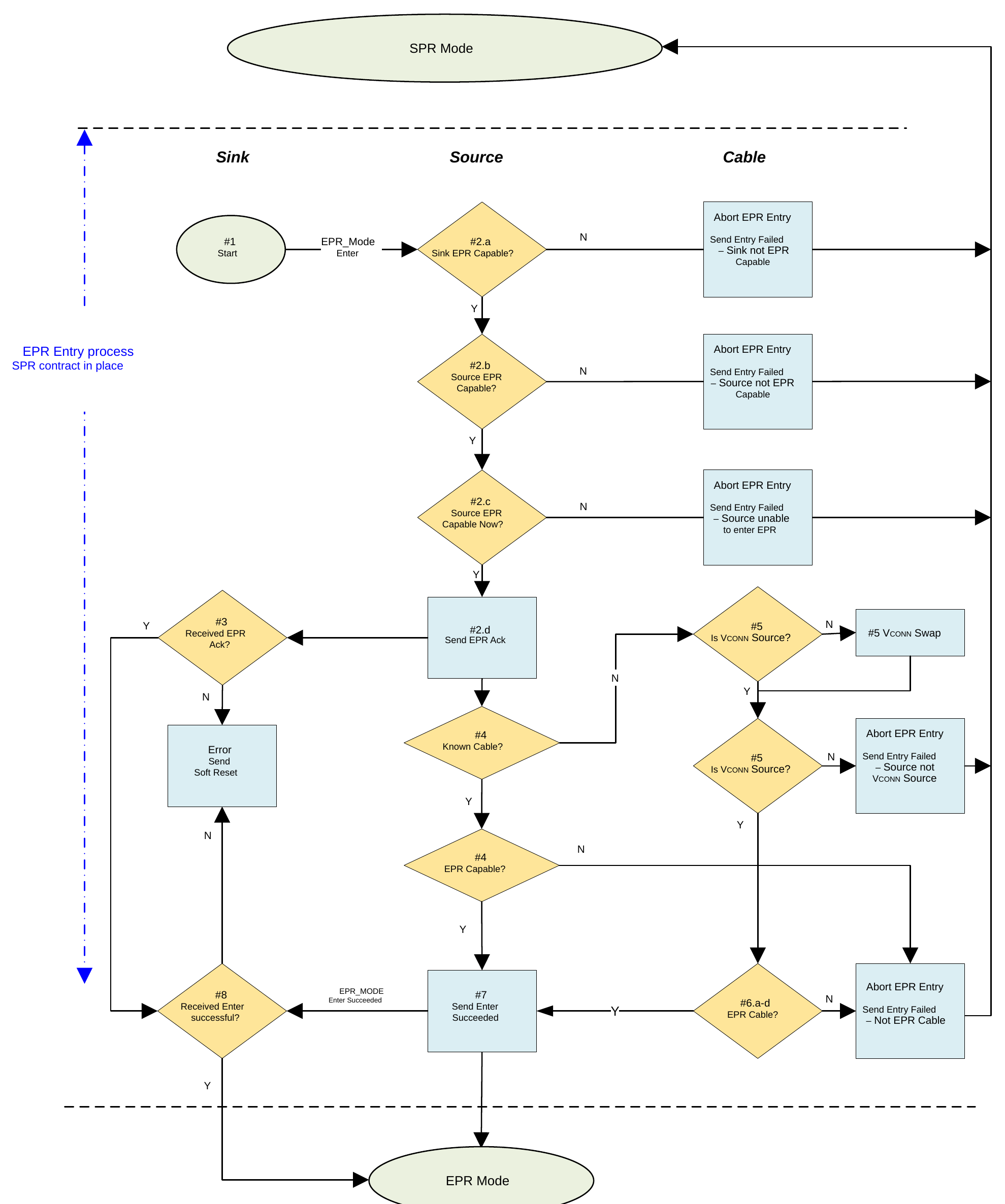
The entry process Shall follow these steps in order:
- The Sink Shall send the EPR_Mode Message with the Action field set to 1 (Enter) and the Data field set to its Operational PDP. If the EPR Source receives an EPR_Mode Message with the Action field not set to Enter it Shall initiate a Soft Reset.
- The Source Shall do the following:
- a. Verify the EPR Capable bit was set in the most recent RDO. If not set, the Source Shall do the following:
- i. Send an EPR_Mode Message with the Action field set to 4 (Enter Failed) and the Data field set to 3 ("EPR Mode Capable bit not set in the RDO").
- ii. Abort the EPR Mode Entry process and remain in the existing SPR Explicit Contract.
- b. Verify the EPR Capable bit was set in the most recent 5V Fixed Supply PDO. If not set, the Source Shall do the following:
- i. Send an EPR_Mode Message with the Action field set to 4 (Enter Failed) and the Data field set to 5 ("EPR Mode Capable bit not set in the Fixed Supply 5V PDO").
- ii. Abort the EPR Mode Entry process and remain in the existing SPR Explicit Contract.
- c. Verify the Source is still able to support EPR Mode. If not, the Source Shall do the following:
- i. Send an EPR_Mode Message with the Action field set to 4 (Enter Failed) and Data field set to 4 ("Unable at this time").
- ii. Abort the EPR Mode Entry process and remain in the existing SPR Explicit Contract. The Sink May at some time in the future send another Request to enter EPR Mode.
- d. Send an EPR_Mode Message with the Action field set to 2 (Enter Acknowledged).
- a. Verify the EPR Capable bit was set in the most recent RDO. If not set, the Source Shall do the following:
- If the Sink receives any Message, other than an EPR_Mode Message with the Action Field set to 2, the Sink Shall initiate a Soft Reset.
- When the EPR Source has used the Discover Identity Command to determine and remembers the Cable Capabilities or the EPR Source is Connected with a captive cable:
- a. If the cable is EPR Capable it Should go directly to Step 7, but May continue to Step 5.
- b. If the cable is not EPR Capable it Shall do the following:
- c. Send an EPR_Mode Message with the Action field set to 4 (Enter Failed) and the Data field set to 1 ("Cable not EPR Capable").
- d. Abort the EPR Mode Entry process and remain in the existing SPR Explicit Contract.
- If the Source is not the VCONN Source, it Shall send a VCONN_Swap Message.
- a. If the Source fails to become the VCONN Source, it Shall:
- i. Send an EPR_Mode Message with the Action field set to 4 (Enter Failed) and the Data field set to 2 (not VCONN Source).
- ii. Abort the EPR Mode Entry process and remain in the existing SPR Explicit Contract.
- a. If the Source fails to become the VCONN Source, it Shall:
- The Source Shall use the Discover Identity Command to read the cable's e-Marker and verify the following:
- a. Cable VDO - Maximum VBUS Voltage (Passive Cable)/Maximum VBUS Voltage (Active Cable) field is
11b(50V) - b. Cable VDO - VBUS Current Handling Capability (Passive Cable)/VBUS Current Handling Capability (Active Cable) field is
10b(5A)
- a. Cable VDO - Maximum VBUS Voltage (Passive Cable)/Maximum VBUS Voltage (Active Cable) field is
- c. Cable VDO - EPR Capable (Passive Cable)/EPR Capable (Active Cable) field is
1b(EPR Capable) - d. If the cable fails to respond to the Discover Identity Command or is not EPR Capable, the Source Shall do the following:
- i. Send an EPR_Mode Message with the Action field set to 4 (Enter Failed) and the Data field to ("Cable not EPR Capable").
- ii. Abort the EPR Mode Entry process and remain in the existing SPR Explicit Contract.
- The Source Shall send the EPR_Mode Message with the Action field set to 3 (Enter Succeeded) and Shall enter EPR Mode.
- If the Sink receives an EPR_Mode Message with the Action field set to 3 (Enter Succeeded) it Shall enter EPR Mode, otherwise it Shall initiate a Soft Reset.
If the EPR Mode Entry process successfully completes within tEnterEPR of the last bit of the GoodCRC Message sent in response to the EPR_Mode Message with the Action field set to 1 (Enter), the Source Shall send an EPR_Source_Capabilities Message within tFirstSourceCap.
If the EPR Mode Entry process has not been aborted or does not complete within tEnterEPR of the last bit of the GoodCRC Message sent in response to the EPR_Mode Message with the Action field set to 1 (Enter), the Sink Shall initiate a Soft Reset.
7.30.2. EPR_Source_Capabilities Message
An EPR Source Shall send the EPR_Source_Capabilities Message:
- When entering EPR Mode
- While in EPR Modes when its Capabilities chang
- In response to an EPR_Get_Source_Cap Message
- After a Soft Reset while in EPR Mode
An EPR Sink operating in EPR Mode Shall evaluate every EPR_Source_Capabilities Message it receives and Shall respond with a EPR_Request Message. If its power consumption exceeds the Source Capabilities, it Shall Re-Negotiate so as not to exceed the Source's most recently Advertised Source Capabilities.
While operating in SPR Mode, an EPR Sink receiving an EPR_Source_Capabilities Message in response to an EPR_Get_Source_Cap Messages Shall Not respond with an EPR_Request Message.
The PDOs or APDOs in an EPR_Source_Capabilities Message Shall only be requested using the EPR_Request Message and only when in EPR Mode.
When Source wants to exit EPR Mode, if not already in power Contract with an SPR PDO or APDO, it Shall send an EPR_Source_Capabilities Message with no EPR PDOs or APDOs (i.e. seven SPR PDOs or APDOs including any zero padded ones). See Section 6.5.18.
7.30.3. EPR_Request Message
An EPR_Request Message Shall be sent by a Sink, operating in EPR Mode, to Request power, typically during the Request phase of a power Negotiation. The EPR_Request Message Shall be sent in response to the most recent EPR_Source_Capabilities Message.
The Source Shall verify the PDO in the EPR_Request Message exactly matches the PDO in the latest EPR_Source_Capabilities Message pointed to by the Object Position field in the RDO.
The Source Shall respond to an EPR_Request Message in the same manner as it responds to a Request Message with an Accept Message, a Reject Message, or a Wait Message. The Explicit Contract Negotiation process for EPR is the same as the process for SPR Mode except that the Source_Capabilities Message is replaced by the EPR_Source_Capabilities Message and the Request Message is replaced by the EPR_Request Message.
- The Accept Message Shall be sent by the Source, in EPR Mode, to signal the Sink that the Source is willing to meet the EPR_Request Message.
- The Reject Message Shall be sent to signal the Sink, in EPR Mode, that the Source is unable to meet the EPR_Request Message. This May be due an Invalid Request or because the Source can no longer provide what it previously Advertised. A mismatch between the requested and advertised PDOs is an example of an Invalid Request.
- The Wait Message May be sent by the Source, in EPR Mode, to signal the Sink that the Source is currently unable to meet the EPR_Request Message.
The Wait Message Shall be sent to signal the Sink, in response to a EPR_Request Message in EPR Mode during Negotiation, to indicate that the Source is currently unable to meet the Request.
7.30.4. EPR_Sink_Capabilities Message
The EPR Sink Shall only send the EPR_Sink_Capabilities Message in response to an EPR_Get_Sink_Cap Message.
7.30.5. Operation in EPR Mode
While operating in EPR Mode, the Source Shall only send EPR_Source_Capabilities Messages to Advertise its power Capabilities and the Sink Shall only respond with EPR_Request Message Messages to Negotiate Explicit Contracts. The EPR_Request Message May be for either an SPR or EPR PDO or APDO.
If the Source sends a Source_Capabilities Message, that is not in response to a Sink Get_Source_Cap Message, the Sink Shall initiate a Hard Reset. If the Sink sends a Request Message, the Source Shall initiate a Hard Reset.
The Source Shall monitor the CC communications path to ensure that there is periodic traffic. The Sink Shall send an EPR_Keep_Alive Message when it has not sent any Messages for more than tSinkEPRKeepAlive to ensure there is timely periodic traffic. If there is no traffic for more than tSourceEPRKeepAlive, the Source Shall initiate a Hard Reset.
A PR_Swap is not allowed while in EPR Mode. The recipient of a PR_Swap Message Shall respond with a Reject Message.
7.30.6. EPR_Keep_Alive Message
The Source operating on EPR Mode responds by returning an EPR_Keep_Alive_Ack Message to the Sink.
See Section 7.31.18.1 and Section 7.31.18.2 for more information on the EPR_Keep_Alive Message.
7.30.7. Exiting EPR Mode
7.30.7.1. Commanded Exit
While in EPR Mode, either the Source or Sink May exit EPR Mode by sending an EPR_Mode Message with the Action field set to 5 (Exit).
The ports Shall be in an Explicit Contract with an SPR PDO or APDO prior to the EPR Mode Exit process by either:
- The Source sending an EPR_Source_Capabilities Message with no EPR PDO or APDO s (e.g., only SPR PDOs or APDOs) or
- The Sink negotiating a new Explicit Contract with bit 31 in the RDO set to zero (e.g., only SPR PDOs or APDOs)).
The process to exit EPR Mode is a multi-Message AMS and Shall follow these steps in order:
- The Port Partners Shall be in an Explicit Contract with an SPR PDO or APDO.
- Either the Source or Sink Shall send an EPR_Mode Message with the Action field set to 5 (Exit) to exit the EPR Mode.
- The Source Shall send a Source_Capabilities Message within tFirstSourceCap of the GoodCRC Message in response to the EPR_Mode Message with the Action field set to 5 (Exit).
- If the Sink does not receive a Source_Capabilities Message within tTypeCSinkWaitCap of the last bit of the GoodCRC Message in response to the EPR_Mode Message with the Action field set to 5 (Exit), Sink Shall initiate a Hard Reset.
7.30.7.2. Implicit Exit
EPR Mode Shall be exited as the side-effect of the Fast Role Swap process. This is because at the end of this process VBUS will be at vSafe5V and the Ports will be in an Implicit Contract. The New Source will then send a Source_Capabilities Message (not an EPR_Source_Capabilities Message) to begin the process of negotiating an SPR Explicit Contract. Once an SPR Explicit Contract is entered, the Source and Sink can then enter EPR Mode if needed.
7.30.7.3. Exits due to errors
Other critical errors can occur while in EPR Mode; these errors Shall result in Hard Reset being initiated by the Port that detects the error. Some of these errors include:
- An EPR_Mode Message with the Action field set to 5 (Exit) to exit EPR Mode is received by a Port in an Explicit Contract with an EPR PDO or APDO.
- The Sink receives an EPR_Source_Capabilities Message with an EPR PDO or APDO in any of the first seven object positions.
- The PDO or APDO in the EPR_Request Message does not match the PDO or APDO in the latest EPR_Source_Capabilities Message pointed to by the Object Position field in the RDO.
- The Source receives a Request Message.
- The Sink receives a Source_Capabilities Message not in response to a Get_Source_Cap Message.
7.30.8. EPR_Get_Source_Cap Message
A Port that can operate as an EPR Source Shall respond by returning an EPR_Source_Capabilities Message.
A Port that does not support EPR Mode as a Source Shall have the following behavior:
- If the Port supports EPR Mode as a Sink and is a DRP Port, it Shall return a Reject Message or Not_Supported Message.
- If the Port does not support EPR Mode as a Sink or is not a DRP Port, it Shall return a Not_Supported Message.
An EPR Capable Sink Port that is operating in SPR Mode Shall treat the EPR_Source_Capabilities Message as informational only and Shall Not respond with an EPR_Request Message.
7.30.9. EPR_Get_Sink_Cap Message
A Port that is EPR Capable operating as a Sink Shall respond by returning an EPR_Sink_Capabilities Message.
A Port that does not support EPR Mode as a Sink Shall behave as follows:
- If the Port supports EPR Mode as a Source and is a DRP Port, it Shall return a Reject Message or Not_Supported Message.
- If the Port does not support EPR Mode as a Source or is not a DRP Port, it Shall return a Not_Supported Message.
7.31. Timers
All the following timers are defined in terms of bits on the bus regardless of where they are implemented in terms of the logical architecture. This is to ensure a fixed reference for the starting and stopping of timers. It is left to the implementer to ensure that this timing is observed in a real system.
7.31.1. CRCReceiveTimer
The CRCReceiveTimer Shall be used by the sender's Protocol Layer to ensure that a Message has not been lost. Failure to receive an acknowledgment of a Message (a GoodCRC Message) whether caused by a bad GoodCRC Message on the receiving end or by a garbled Message within tReceive is detected when the CRCReceiveTimer expires. The sender's Protocol Layer response when a CRCReceiveTimer expires Shall be to retry nRetryCount times.
Note: Cable Plugs do not retry Messages and large Extended Messages that are not Chunked are not retried (see Section 7.32.4"). Sending of the Preamble corresponding to the retried Message Shall start within tRetry of the CRCReceiveTimer expiring.
The CRCReceiveTimer Shall be started when the last bit of the Message EOP has been transmitted by the PHY Layer. The CRCReceiveTimer Shall be stopped when the last bit of the EOP corresponding to the GoodCRC Message has been received by the PHY Layer. The Protocol Layer receiving a Message Shall respond with a GoodCRC Message within tTransmit in order to ensure that the sender's CRCReceiveTimer does not expire. The tTransmit time Shall be measured from when the last bit of the Message EOP has been received by the PHY Layer until the first bit of the Preamble of the GoodCRC Message has been transmitted by the PHY Layer.
7.31.2. SenderResponseTimer
The SenderResponseTimer Shall be used by the sender's Policy Engine to ensure that a Message requesting a response (e.g., Get_Source_Cap Message) is responded to within a bounded time of tSenderResponse. Failure to receive the expected response is detected when the SenderResponseTimer expires. For Extended Messages received as Chunks, the SenderResponseTimer will also be started and stopped by the Chunked Rx State Machine. See Section 9.2.2 for more details of the SenderResponseTimer operation. The Policy Engine's response when the SenderResponseTimer expires Shall be dependent on the Message sent. The SenderResponseTimer Shall be started from the time the last bit of the GoodCRC Message EOP, corresponding to the Message requesting a response, has been received by the PHY Layer. The SenderResponseTimer Shall be stopped when the last bit of the EOP of the GoodCRC Message, corresponding to the expected response Message, has been transmitted by the PHY Layer. The receiver of a Message requiring a response Shall respond within tReceiverResponse in order to ensure that the sender's SenderResponseTimer does not expire. The tReceiverResponse time Shall be measured from the time the last bit of the GoodCRC Message EOP, corresponding to the expected Request Message, has been transmitted by the PHY Layer until the first bit of the response Message Preamble has been transmitted by the PHY Layer.
7.31.3. Capability Timers
Sources and Sinks use Capability Timers to determine Attachment of a PD Capable Device. By periodically sending or requesting Capabilities, it is possible to determine PD Device Attachment when a response is received.
7.31.3.1. SourceCapabilityTimer
Prior to the First Explicit Contract a Source Shall use the SourceCapabilityTimer to periodically send out a Source_Capabilities Message every tTypeCSendSourceCap while:
- The Port is Attached.
- The Source is not in an active connection with a PD Sink Port.
Whenever there is a SourceCapabilityTimer timeout the Source Shall send a Source_Capabilities Message Message. It Shall then re-initialize and restart the SourceCapabilityTimer. The SourceCapabilityTimer Shall be stopped when the last bit of the EOP corresponding to the GoodCRC Message has been received by the PHY Layer since a PD connection has been established. At this point, the Source waits for a Request Message or a response timeout.
Note: The Source can also stop sending Source_Capabilities Message after nCapsCount Messages have been sent without a GoodCRC Message response (see Section 7.32.6). See Section 9.2.3 for more details of when Source_Capabilities Messages are transmitted.
7.31.3.2. SinkWaitCap Timer
While in a Default Contract or an Implicit Contract when a Sink observes an absence of Source_Capabilities Messages, after VBUS is present, for a duration of tTypeCSinkWaitCap the Sink May issue Hard Reset Signaling in order to restart the sending of Source_Capabilities Messages by the Source (see Section 7.32.6) or continue to operate at USB Type-C current. When a Sink, entering EPR Mode, observes an absence of EPR_Source_Capabilities Messages, after the GoodCRC Message acknowledging the EPR_Mode Message with the Action field set to 3 (Enter Succeeded), for a duration of tTypeCSinkWaitCap the Sink Shall issue Hard Reset Signaling in order to exit EPR Mode (see Section 6.4.9).
When a Sink, exiting EPR Mode, observes an absence of Source_Capabilities Messages, after the GoodCRC Message acknowledging the EPR_Mode Message with the Action field set to 5 (Exit), for a duration of tTypeCSinkWaitCap the Sink Shall issue Hard Reset Signaling in order to restart the sending of Source_Capabilities Messages by the Source (see Section 7.32.6). See Section 9.2.4 for more details of when the SinkWaitCapTimer is run.
7.31.3.3. tFirstSourceCap
After Port Partners are Attached or after a Hard Reset or after a Power Role Swap or after a Fast Role Swap a Source Shall send its first Source_Capabilities Message within tFirstSourceCap of VBUS reaching vSafe5V. After Soft Reset, a Source Shall send its first Source Capabilities Message within tFirstSourceCap after the last bit of the GoodCRC Message EOP corresponding to the Accept Message. This ensures that the Sink receives a Source Capabilities Message before the Sink's SinkWaitCapTimer expires.
A Source entering EPR Mode Shall send its first EPR_Source_Capabilities Message within tFirstSourceCap of the GoodCRC Message acknowledging the EPR_Mode Message with the Action field set to 3 (Enter Succeeded). A Source exiting EPR Mode Shall send its first Source_Capabilities Message within tFirstSourceCap of the GoodCRC Message acknowledging the EPR_Mode Message with the Action field set to 5 (Exit).
7.31.4. Wait Timers and Times
7.31.4.1. SinkRequestTimer
The SinkRequestTimer is used to ensure that the time before the next Sink Request Message, after a Wait Message has been received from the Source in response to a Sink Request Message (see Section 7.9.2.2), is a minimum of tSinkRequest. The SinkRequestTimer Shall be started when the EOP of a Wait Message has been received and Shall be stopped if any other Message is received or during a Hard Reset. The Sink Shall wait at least tSinkRequest, after receiving the EOP of a Wait Message sent in response to a Sink Request Message, before sending a new Request Message. Whenever there is a SinkRequestTimer timeout, the Sink May send a Request Message. It Shall then re-initialize and restart the SinkRequestTimer.
7.31.4.2. tPRSwapWait
The time before the next PR_Swap Message, after a Wait Message has been received in response to a PR_Swap Message (see Section 7.10.1) is a minimum of tPRSwapWait min. The Port Shall wait at least tPRSwapWait after receiving the EOP of a Wait Message sent in response to a PR_Swap Message, before sending a new PR_Swap Message.
7.31.4.3. tDRSwapWait
The time before the next DR_Swap Message, after a Wait Message has been received in response to a DR_Swap Message (see Section 7.12.2) is a minimum of tDRSwapWait min. The Port Shall wait at least tDRSwapWait after receiving the EOP of a Wait Message sent in response to a DR_Swap Message, before sending a new DR_Swap Message.
7.31.4.4. tVconnSwapWait
The time before the next VCONN_Swap Message, after a Wait Message has been received in response to a VCONN_Swap Message (see Section 7.13.1) is a minimum of tVconnSwapWait min. The Port Shall wait at least tVconnSwapWait after receiving the EOP of a Wait Message sent in response to a VCONN_Swap Message, before sending a new VCONN_Swap Message.
7.31.4.5. tVconnSwapDelayDFP
The time delay for DFP after losing VCONN Source role due to an incoming VCONN Swap Request from UFP and before sending the next VCONN_Swap Message. The DFP Shall wait at least tVconnSwapDelayDFP after sending the EOP of the GoodCRC Message in response to PS_RDY Message received at the end of the previous VCONN Swap AMS.
7.31.4.6. tVconnSwapDelayUFP
The time delay for UFP after losing VCONN Source role due to an incoming VCONN Swap Request from DFP and before sending the next VCONN_Swap Message. The UFP Shall wait at least tVconnSwapDelayUFP after sending the EOP of the GoodCRC Message in response to PS_RDY Message received at the end of the previous VCONN Swap AMS.
7.31.4.7. tEnterUSBWait
The time before the next Enter_USB Message, after a Wait Message has been received in response to a Enter_USB Message (see Section 7.29.1) is a minimum of tEnterUSBWait min. The DFP Shall wait at least tEnterUSBWait after receiving the EOP of a Wait Message sent in response to an Enter_USB Message, before sending a new Enter_USB Message.
7.31.5. Power Supply Timers
See Section 4.5 for diagrams showing the usage of the timers in this section.
7.31.5.1. PSTransition Timer
The PSTransitionTimer is used by the Policy Engine to timeout on a PS_RDY Message. It is started when a Request for New Source Capabilities has been accepted and will timeout after tPSTransition if a PS_RDY Message has not been received. This condition leads to a Hard Reset and a return to USB Default Operation. The PSTransitionTimer relates to the time taken for the Source to transition from one voltage, or current level, to another (see Section 4.1).
The PSTransitionTimer Shall be started when the last bit of the GoodCRC Message EOP, corresponding to an Accept Message, has been transmitted by the PHY Layer. The PSTransitionTimer Shall be stopped when the last bit of the GoodCRC Message EOP, corresponding to the PS_RDY Message, has been transmitted by the PHY Layer.
7.31.5.2. PSSourceOffTimer
Use during Power Role Swap
The PSSourceOffTimer is used by the Policy Engine in Dual-Role Power Device that is currently acting as a Sink to timeout on a PS_RDY Message during a Power Role Swap AMS. This condition leads to USB Type-C Error Recovery. If a PR_Swap Message Request has been sent by the Dual-Role Power Device currently acting as a Source the Sink can respond with an Accept Message. When the last bit of the GoodCRC Message EOP, corresponding to this transmitted Accept Message, is received by the Sink's PHY Layer, then the PSSourceOffTimer Shall be started.
If a PR_Swap Message Request has been sent by the Dual-Role Power Device currently acting as a Sink the Source can respond with an Accept Message. When the last bit of the GoodCRC Message EOP, corresponding to this received Accept Message, is transmitted by the Sink's PHY Layer, then the PSSourceOffTimer Shall be started. The PSSourceOffTimer Shall be stopped when the last bit of the GoodCRC Message EOP, corresponding to the received PS_RDY Message, is transmitted by the PHY Layer. The PSSourceOffTimer relates to the time taken for the remote Dual-Role Power Device to stop supplying power (see Section 4.3.3). The timer Shall time out if a PS_RDY Message has not been received from the remote Dual-Role Power Device within tPSSourceOff indicating this has occurred.
Use during Fast Role Swap
The PSSourceOffTimer is used by the Policy Engine in Dual-Role Power Device that is the Initial Sink (currently providing vSafe5V) to timeout on a PS_RDY Message during a Fast Role Swap AMS. This condition leads to USB Type-C Error Recovery. When the FR_Swap Message Request has been sent by the Initial Sink, the Initial Source Shall respond with an Accept Message. When the last bit of the GoodCRC Message EOP, corresponding to this Accept Message is received by the Initial Sink's PHY Layer, then the PSSourceOffTimer Shall be started. The PSSourceOffTimer Shall be stopped when the last bit of the GoodCRC Message EOP, corresponding to the received PS_RDY Message, is transmitted by the PHY Layer. The PSSourceOffTimer relates to the time taken for the Initial Source to stop supplying power and for VBUS to revert to vSafe5V (see Figure 10.3). The timer Shall time out if a PS_RDY Message has not been received from the Initial Source within tPSSourceOff indicating this has occurred.
7.31.5.3. PSSourceOnTimer
Use during Power Role Swap
The PSSourceOnTimer is used by the Policy Engine in Dual-Role Power Device that has just stopped sourcing power and is waiting to start sinking power to timeout on a PS_RDY Message during a Power Role Swap. This condition leads to USB Type-C Error Recovery.
The PSSourceOnTimer Shall be started when:
- The last bit of the GoodCRC Message EOP, corresponding to the transmitted PS_RDY Message, is received by the PHY Layer.
- The PSSourceOnTimer Shall be stopped when:
- The last bit of the GoodCRC Message EOP, corresponding to the received PS_RDY Message, is transmitted by the PHY Layer.
The PSSourceOnTimer relates to the time taken for the remote Dual-Role Power Device to start sourcing power (see Section 4.3.3) and will time out if a PS_RDY Message indicating this has not been received within tPSSourceOn.
Use during Fast Role Swap
The PSSourceOnTimer is used by the Policy Engine in Dual-Role Power Device that has just stopped sourcing power and is waiting to start sinking power to timeout on a PS_RDY Message during a Fast Role Swap. This condition leads to USB Type-C Error Recovery.
The PSSourceOnTimer Shall be started when:
- The last bit of the GoodCRC Message EOP, corresponding to the transmitted PS_RDY Message, is received by the PHY Layer.
- The PSSourceOnTimer Shall be stopped when:
- The last bit of the GoodCRC Message EOP, corresponding to the received PS_RDY Message, is transmitted by the PHY Layer.
The PSSourceOnTimer relates to the time taken for the remote Dual-Role Power Device to start sourcing power (see Section 10.1) and will time out if a PS_RDY Message indicating this has not been received within tPSSourceOn.
7.31.5.4. NoResponseTimer
The NoResponseTimer is used by the Policy Engine in a Source to determine that its Port Partner is not responding after a Hard Reset. When the NoResponseTimer times out, the Policy Engine Shall issue up to nHardResetCount additional Hard Resets before determining that the Port Partner is non-responsive to USB Power Delivery messaging. If the Source fails to receive a GoodCRC Message in response to a Source_Capabilities Message within tNoResponse of:
- The last bit of a Hard Reset Signaling being sent by the PHY Layer if the Hard Reset Signaling was initiated by the Sink.
- The last bit of a Hard Reset Signaling being received by the PHY Layer if the Hard Reset Signaling was initiated by the Source.
- Then the Source Shall issue additional Hard Resets up to nHardResetCount times (see Section 7.1.3).
For a non-responsive Device, the Policy Engine in a Source May either decide to continue sending Source_Capabilities Messages or to go to non-USB Power Delivery operation and cease sending Source_Capabilities Messages.
7.31.6. BIST Timers
7.31.6.1. tBISTCarrierMode
tBISTCarrierMode is used to define the maximum time that a UUT has to enter BIST Carrier Mode when requested by a Tester. A UUT Shall enter BIST Carrier Mode within tBISTCarrierMode of the last bit of the GoodCRC Message EOP, corresponding to the received the BIST Message used to initiate the test, being transmitted by the PHY Layer. In BIST Carrier Mode when transmitting a continuous carrier signal transmission Shall start as soon as the UUT enters BIST Mode.
7.31.6.2. BISTContModeTimer
The BISTContModeTimer is used by a UUT to ensure that a Continuous BIST Mode (i.e., BIST Carrier Mode) is exited in a timely fashion. A UUT that has been put into a Continuous BIST Mode Shall return to normal operation (either PE_SRC_Transition_to_default, PE_SNK_Transition_to_default, or PE_CBL_Ready) within tBISTContMode of starting to transmit a continuous carrier signal.
7.31.6.3. tBISTSharedTestMode
tBISTSharedTestMode is used to define the maximum time that a UUT has to enter BIST Shared Capacity Test Mode when requested by a Tester. A UUT Shall enter BIST Shared Capacity Test Mode and send a new Source_Capabilities Message from all Ports within the Shared Capacity Port within tBISTSharedTestMode of the last bit of the GoodCRC Message. Message EOP, corresponding to the received the BIST Message used to initiate the test, being transmitted by the PHY Layer.
7.31.7. Power Role Swap Timers
7.31.7.1. SwapSourceStartTimer
The SwapSourceStartTimer Shall be used by the New Source, after a Power Role Swap or Fast Role Swap, to ensure that it does not send Source_Capabilities Message before the New Sink is ready to receive the Source_Capabilities Message. The New Source Shall Not send the Source_Capabilities Message earlie than tSwapSourceStart after the last bit of the EOP of GoodCRC Message sent in response to the PS_RDY Message sent by the New Source indicating that its power supply is ready. The Sink Shall be ready to receive a Source_Capabilities Message tSwapSinkReady after having sent the last bit of the EOP of GoodCRC Message sent in response to the PS_RDY Message sent by the New Source indicating that its power supply is ready.
7.31.8. Soft Reset Timers
7.31.8.1. tSoftReset
A failure to see a GoodCRC Message in response to any Message within tReceive (after nRetryCount retries), when a Port Pair is Connected, is indicative of a communications failure. This Shall cause the Source or Sink to send a Soft_Reset Message, transmission of which Shall be completed within tSoftReset of the CRCReceiveTimer expiring.
7.31.8.2. tProtErrSoftReset
If the Protocol Error occurs that causes the Source or Sink to send a Soft_Reset Message, the transmission of the Soft_Reset Message Shall be completed within tProtErrSoftReset of the EOP of the GoodCRC Message sent in response to the Message that caused the Protocol Error.
7.31.9. Data Reset Timers
7.31.9.1. VCONNDischargeTimer
The VCONNDischargeTimer is used by the Policy Engine in the DFP to ensure the UFP actively discharges VCONN in a timely manner to ensure the cable will restore Ra. Once the UFP has discharged VCONN below vRaReconnect (see [USB-C]) it sends a PS_RDY Message (see also Section 4.6).
If the DFP does not receive a PS_RDY Message from the UFP within tVCONNSourceDischarge of the last bit of the GoodCRC Message acknowledging the Accept Message in response to the Data_Reset Message, the VCONNDischargeTimer will time out and the Policy Engine Shall enter the ErrorRecovery State.
7.31.9.2. tDataReset
The DFP Shall complete the Data_Reset process (see Section 7.1.2") within tDataReset of the last bit of the GoodCRC Message EOP, corresponding to the Accept Message, being transmitted by the PHY Layer.
7.31.9.3. DataResetFailTimer
The DataResetFailUFPTimer Shall be used by the DFP's Policy Engine to ensure the Data Reset process completes within tDataResetFailUFP of the last bit of the GoodCRC Message acknowledging the Accept Message in response to the Data_Reset Message. If the DFP's DataResetFailUFPTimer expires, the DFP Shall enter the ErrorRecovery State.
7.31.9.4. DataResetFailUFPTimer
The DataResetFailUFPTimer Shall be used by the UFP's Policy Engine to ensure the Data Reset process completes within tDataResetFailUFP of the last bit of the GoodCRC Message acknowledging the Accept Message in response to the Data_Reset Message. If the UFP's DataResetFailUFPTimer expires, the UFP Shall enter the ErrorRecovery State.
7.31.10. Hard Reset Timers
7.31.10.1. HardResetCompleteTimer
The HardResetCompleteTimer is used by the Protocol Layer in the case where it has asked the PHY Layer to send Hard Reset Signaling and the PHY Layer is unable to send the Signaling within a reasonable time due to a non-Idle channel. If the PHY Layer does not indicate that the Hard Reset Signaling has been sent within tHardResetComplete of the Protocol Layer requesting transmission, then the Protocol Layer Shall inform the Policy Engine that the Hard Reset Signaling has been sent in order to ensure the power supply is reset in a timely fashion.
7.31.10.2. PSHardResetTimer
The PSHardResetTimer is used by the Policy Engine in a Source to ensure that the Sink has had sufficient time to process Hard Reset Signaling before turning off its power supply to VBUS. When a Hard Reset occurs the Source, stops driving VCONN, removes Rp from the CC pin and starts to transition the VBUS voltage to vSafe0V either:
- tPSHardReset after the last bit of the Hard Reset Signaling has been received from the Sink or
- tPSHardReset after the last bit of the Hard Reset Signaling has been sent by the Source. See Section 4.4.
7.31.10.3. tDRSwapHardReset
If a DR_Swap Message is received during Modal Operation then a Hard Reset Shall be initiated by the recipient of the unexpected DR_Swap Message; Hard Reset Signaling Shall be generated within tDRSwapHardReset of the EOP of the GoodCRC Message sent in response to the DR_Swap Message.
7.31.10.4. tProtErrHardReset
If a Protocol Error occurs that directly leads to a Hard Reset, the transmission of the Hard Reset Signaling Shall be completed within tProtErrHardReset of the EOP of the GoodCRC Message sent in response to the Message that caused the Protocol Error.
7.31.10.5. tSendHardReset
When a timer expiration leads to sending a Hard Reset, the transmission of the last bit of the Hard Reset Message Shall be completed within tSendHardReset. tSendHardReset applies to the expiration of:
- SenderResponseTimer,
- SourcePPSCommTimer or
- SourceEPRKeepAliveTimer.
7.31.10.6. tInitiateErrorRecovery
When an event or timer expiration leads to ErrorRecovery, the ErrorRecovery State Shall be entered within tInitiateErrorRecovery.
7.31.11. Structured VDM Timers
7.31.11.1. VDMResponseTimer
The VDMResponseTimer Shall be used by the Initiator's Policy Engine to ensure that a Structured VD Command Request needing a response (e.g. Discover Identity Command Request) is responded to withi a bounded time of tVDMSenderResponse. The VDMResponseTimer Shall be applied to all Structure VDM Commands except the Enter Mode and Exit Mode Commands which have their own timer (VDMModeEntryTimer and VDMModeExitTimer respectively). Failure to receive the expected response is detected when the VDMResponseTimer expires.
The Policy Engine's response when the VDMResponseTimer expires Shall depend on the Message sent (see Section 7.5 and Section 9.2). The VDMResponseTimer Shall be started from the time the last bit of the GoodCRC Message EOP corresponding to the VDM Command requesting a response, has been received by the PHY Layer. The VDMResponseTimer Shall be stopped when the last bit of the EOP of the GoodCRC Message, corresponding to the expected VDM Command response, has been transmitted by the PHY Layer. The receiver of a Message requiring a response Shall respond within tVDMReceiverResponse in order to ensure that the sender's VDMResponseTimer does not expire. The tVDMReceiverResponse time Shall be measured from the time the last bit of the Message EOP has been transmitted by the PHY Layer until the first bit of the response Message Preamble has been transmitted by the PHY Layer.
7.31.11.2. VDMModeEntryTimer
The VDMModeEntryTimer Shall be used by the Initiator's Policy Engine to ensure that the response to a Structured VDM Enter Mode Command Request (ACK or NAK with ACK indicating that the requested Alternate Mode has been entered) arrives within a bounded time of tVDMWaitModeExit. Failure to receive the expected response is detected when the VDMModeEntryTimer expires. The Policy Engine's response when the VDMModeEntryTimer expires is to inform the Device Policy Manager (see Section 9.2.24.1.1).
The VDMModeEntryTimer Shall be started from the time the last bit of the EOP of the GoodCRC Message, corresponding to the VDM Command Request, has been received by the PHY Layer. The VDMModeEntryTimer Shall be stopped when the last bit of the EOP of the GoodCRC Message, corresponding to the expected Structured VDM Command response (ACK, NAK or BUSY), has been transmitted by the PHY Layer.
The receiver of a Message requiring a response Shall respond within tVDMEnterMode in order to ensure that the sender's VDMModeEntryTimer does not expire. The tVDMEnterMode time Shall be measured from the time the last bit of the EOP of the GoodCRC Message, corresponding to VDM Command Request, has been transmitted by the PHY Layer until the first bit of the response Message Preamble has been transmitted by the PHY Layer.
7.31.11.3. VDMModeExitTimer
The VDMModeExitTimer Shall be used by the Initiator's Policy Engine to ensure that the ACK response to a Structured VDM Exit Mode Command, indicating that the requested Alternate Mode has been exited, arrives within a bounded time of tVDMWaitModeExit. Failure to receive the expected response is detected when the VDMModeExitTimer expires. The Policy Engine's response when the VDMModeExitTimer expires is to inform the Device Policy Manager (see Section 9.2.24.2.1). The VDMModeExitTimer Shall be started from the time the last bit of the GoodCRC Message EOP, corresponding to the VDM Command requesting a response, has been received by the PHY Layer. The VDMModeExitTimer Shall be stopped when the last bit of the GoodCRC Message EOP, corresponding to the expected Structured VDM Command response ACK, has been transmitted by the PHY Layer. The receiver of a Message requiring a response Shall respond within tVDMExitMode in order to ensure that the sender's VDMModeExitTimer does not expire. The tVDMExitMode time Shall be measured from the time the last bit of the Message EOP has been received by the PHY Layer until the first bit of the response Message Preamble has been transmitted by the PHY Layer.
7.31.11.4. tVDMBusy
The Initiator Shall wait at least tVDMBusy, after receiving a BUSY Command response, before repeating the Structured VDM Request again.
7.31.12. VCONN Timers
7.31.12.1. VconnOnTimer
The VconnOnTimer is used during a VCONN Swap.
The VconnOnTimer Shall be started when:
- The last bit of GoodCRC Message EOP, corresponding to the Accept Message, is transmitted or received by the PHY Layer.
The VconnOnTimer Shall be stopped when:
- The last bit of the GoodCRC Message EOP, corresponding to the PS_RDY Message, is transmitted by the PHY Layer.
Prior to sending the PS_RDY Message, the Port Shall have turned VCONN On.
7.31.12.2. tVconnSourceOff
The tVconnSourceOff time applies during a VCONN Swap. The initial VCONN Source Shall cease sourcing VCONN within tVconnSourceOff of the last bit of the GoodCRC Message EOP, corresponding to the PS_RDY Message, being transmitted by the PHY Layer.
7.31.12.3. tCableMessage
When Ports on both ends are compliant with Revision 3.x of the specification, the ports Shall Not wait tCableMessage before sending an SOP' Packet or SOP'' Packet even when communicating using [PD2] with a Cable Plug. This specification defines Collision Avoidance mechanisms that obviate the need for this time. Cable Plugs Shall only wait tCableMessage before sending an SOP' Packet or SOP'' Packet when operating at [PD2]. When operating at Revisions higher than [PD2] Cable Plugs Shall Not wait tCableMessage before sending an SOP' Packet or SOP'' Packet.
7.31.12.4. DiscoverIdentityTimer
The DiscoverIdentityTimer is used prior to or during an Explicit Contract when discovering whether a Cable Plug is PD Capable using SOP'. When performing Cable Discovery during an Explicit Contract the Discover Identity Command Request Shall be sent every tDiscoverIdentity. No more than nDiscoverIdentityCount Discover Identity Messages without a GoodCRC Message response Shall be sent. If no GoodCRC Message response is received after nDiscoverIdentityCount Discover Identity Command requests have been sent by a Port, the Port Shall Not send any further SOP'/SOP'' Messages.
7.31.13. Collision Avoidance Timers
7.31.13.1. SinkTxTimer
The SinkTxTimer is used by the Protocol Layer in a Source to allow the Sink to complete its transmission before initiating an AMS. The Source Shall wait a minimum of tSinkTx after changing Rp from SinkTxOK to SinkTxNG before initiating an AMS by sending a Message. A Sink Shall only initiate an AMS when it has determined that Rp is set to SinkTxOK.
7.31.13.2. tSrcHoldsBus
If a transition into the PE_SRC_Ready State will result in an immediate transition out of the PE_SRC_Ready State within tSrcHoldsBus e.g. it is due to a Protocol Error that has not resulted in a Soft Reset, then the notifications of the end of AMS and first Message in an AMS May Not be sent to avoid changing the Rp value unnecessarily.
7.31.14. Fast Role Swap Timers
See Section 10.1 for more information on the use of Fast Role Swap timers.
7.31.14.1. tFRSwap5V
The tFRSwap5V time Shall be measured from:
The later of:
- The last bit of the GoodCRC Message EOP, corresponding to the Accept Message or
- VBUS being within vSafe5V.
- Until the first bit of the response PS_RDY Message Preamble has been transmitted by the PHY Layer.
During a Fast Role Swap, the Initial Source Shall start the PS_RDY Message within tFRSwap5V after both:
- The Initial Source has sent the Accept Message, and
- VBUS is at or below vSafe5V.
7.31.14.2. tFRSwapComplete
During a Fast Role Swap, the Initial Sink Shall respond with a the PS_RDY Message within tFRSwapComplete after it has received the PS_RDY Message from the Initial Source. The tFRSwapComplete time Shall be measured from the time the last bit of the GoodCRC Message EOP, corresponding to the PS_RDY Message, has been transmitted by the PHY Layer until the first bit of the response PS_RDY Message Preamble has been transmitted by the PHY Layer.
7.31.14.3. tFRSwapInit
That last bit of the EOP of the FR_Swap Message Shall be transmitted by the New Source no later than tFRSwapInit after the Fast Role Swap Request has been detected (see Section 10.3)
7.31.15. Chunking Timers
7.31.15.1. ChunkingNotSupportedTimer
The ChunkingNotSupportedTimer is used by a Source or Sink which does not support multi-Chunk Chunking but has received a Message Chunk.
The ChunkingNotSupportedTimer Shall be started when:
The last bit of the GoodCRC Message EOP, corresponding to a Message Chunk of a multi-Chunk Message, is transmitted by the PHY Layer. The Policy Engine Shall Not send its Not_Supported Message before the ChunkingNotSupportedTimer expires.
7.31.15.2. ChunkSenderRequestTimer
The ChunkSenderResponseTimer is used during a Chunked Message transmission. The ChunkSenderResponseTimer Shall be used by the sender's Chunking State machine to ensure that a Chunk Response is responded to within a bounded time of tChunkSenderResponse. Failure to receive the expected response is detected when the ChunkSenderResponseTimer expires.
The ChunkSenderResponseTimer Shall be started when:
The last bit of the GoodCRC Message EOP, corresponding to the Chunk Response Message, is received by the PHY Layer.
The ChunkSenderResponseTimer Shall be stopped when:
- The last bit of the EOP of the GoodCRC Message, corresponding to the Chunk Request Message, is transmitted by the PHY Layer.
- A Message other than a Chunk Request is received from the Protocol Layer Rx.
The receiver of a Chunk Response requiring a Chunk Request Shall respond with a Chunk Request within tChunkReceiverRequest in order to ensure that the sender's ChunkSenderRequestTimer does not expire.
The tChunkReceiverRequest time Shall be measured from the time the last bit of the EOP of the GoodCRC Message, corresponding to the Chunk Response Message, has been transmitted by the PHY Layer until the first bit of the response Message Preamble has been transmitted by the PHY Layer.
7.31.15.3. ChunkSenderResponseTimer
The ChunkSenderResponseTimer is used during a Chunked Message transmission. The ChunkSenderResponseTimer Shall be used by the sender's Chunking State machine to ensure that a Chunk Request is responded to within a bounded time of tChunkSenderResponse. Failure to receive the expected response is detected when the ChunkSenderResponseTimer expires.
The ChunkSenderResponseTimer Shall be started when:
The last bit of the GoodCRC Message EOP, corresponding to the Chunk Request Message, is received by the PHY Layer.
The ChunkSenderResponseTimer Shall be stopped when:
The last bit of the GoodCRC Message EOP, corresponding to the Chunk Response Message, is transmitted by the PHY Layer.
A Message other than a Chunk is received from the Protocol Layer. The receiver of a Chunk Request requiring a Chunk Response Shall respond with a Chunk Response within tChunkReceiverResponse in order to ensure that the sender's ChunkSenderResponseTimer does not expire. The tChunkReceiverResponse time Shall be measured from the time the last bit of the EOP of th GoodCRC Message, corresponding to the Chunk Request Message, has been transmitted by the PHY Layer until the first bit of the response Message Preamble has been transmitted by the PHY Layer.
7.31.16. Programmable Power Supply Timers
7.31.16.1. SinkPPSPeriodicTimer
The SinkPPSPeriodicTimer Shall be used by the Sink's Policy Engine to ensure that communication between the Sink and Source occurs within a bounded time of tPPSRequest when in PPS Mode. In the absence of any other traffic, a Request Message requesting a PPS APDO is sent periodically as a keep alive mechanism.
SinkPPSPeriodicTimer Shall be re-initialized and restarted on transmission, by the PHY Layer, of the last bit of the GoodCRC Message EOP, corresponding to any received Message, that causes the Sink to enter the PE_SNK_Ready State. The Sink Shall stop the SinkPPSPeriodicTimer on transmission, by the PHY Layer, of the last bit of the GoodCRC Message EOP, corresponding to any Message, or the last bit of any Signaling is received, by the PHY Layer, from the Source and by the Sink that causes the Sink to leave the PE_SNK_Ready State.
7.31.16.2. SourcePPSCommTimer
The SourcePPSCommTimer Shall be used by the Source's Policy Engine to ensure that communication between the Sink and Source occurs within a bounded time of tPPSTimeout when in PPS Mode. In the absence of any other traffic, a Request Message requesting a PPS APDO is received periodically as a keep alive mechanism.
SourcePPSCommTimer Shall be re-initialized and restarted when, after receiving any Message that causes the Source to enter the PE_SRC_Ready State, the last bit of the corresponding GoodCRC Message EOP is transmitted by the PHY Layer.
The Source Shall stop the SourcePPSCommTimer when:
-
After receiving any Message that causes the Source to leave the
PE_SRC_ReadyState, the last bit of the of the corresponding GoodCRC Message EOP is sent by the PHY Layer, or -
The last bit of any Signaling is received by the PHY Layer from the Sink by the Source that causes the Source to leave the
PE_SRC_ReadyState. When theSourcePPSCommTimertimes out the Source Shall issue Hard Reset Signaling.
7.31.17. tEnterUSB
The DFP Shall send the Enter_USB Message within tEnterUSB of either:
-
The last bit of the GoodCRC Message acknowledging the Data_Reset_Complete Message in response to the Data_Reset Message or
-
A PD Connection, specifically the last bit of the GoodCRC Message acknowledging the Source_Capabilities Message after the initial entry into the
PE_SRC_Send_CapabilitiesState or
The last bit of the GoodCRC Message acknowledging the Accept Message in response to the DR_Swap Message Failure by the DFP to meet this timeout parameter can result in the ports not transitioning into [USB4] operation. Any AMS initiated by the UFP prior to receiving the Enter_USB Message will delay reception of the Enter_USB Message and [USB4] operation, therefore a USB4 -capable UFP Should Not initiate any AMS until the DFP has been given time to send the Enter_USB Message.
7.31.18. EPR Timers
7.31.18.1. SinkEPREnterTimer
The SinkEPREnterTimer is used to ensure the EPR Mode Entry process completes within tEnterEPR. The Sink Shall start the timer when it sees the last bit of the GoodCRC Message in response to the EPR_Mode Message with the Action field set to 1 (Enter). The Sink Shall stop the timer when the last bit of the corresponding GoodCRC Message EOP, corresponding to the received EPR_Mode Message withthe Action field set to 3 (Enter Succeeded), has been transmitted by the PHY Layer. If the timer expires the Sink Shall send a Soft_Reset Message.
7.31.18.2. SourceEPRKeepAlive Timer
The SinkEPRKeepAliveTimer Shall be used by the Sink's Policy Engine to ensure that communication between the Sink and Source occurs within a bounded time of tSinkEPRKeepAlive. The Sink Shall initialize and run this timer upon entry into the PE_SNK_Ready State when in EPR Mode and Shall stop it upon exit from the PE_SNK_Ready when in EPR Mode.
While operating in EPR Mode, the Sink Shall stop the SinkEPRKeepAliveTimer timer whenever:
-
The last bit of the GoodCRC Message EOP, in response any Message from the Source, is transmitted by the PHY Layer.
-
The PHY Layer receives the last bit of the GoodCRC Message EOP in response to any Message sent tothe Source.
If the timer expires the Sink Shall send an EPR_Keep_Alive Message.
7.31.18.3. tEPRSourceCableDiscovery
After Port Partners are Attached or after a Hard Reset or after a Power Role Swap or after a Fast Role Swap an EPR Source Shall discover the Cable Plug within tEPRSourceCableDiscovery of entering the First Explicit Contract.
The EPR Source Shall send the Discover Identity REQ Command, to the Cable Plug, within tEPRSourceCableDiscovery of receiving the GoodCRC Message acknowledging the PS_RDY Message as part of the Explicit Contract Negotiation.
Note: If the EPR Source is not the VCONN Source, tEPRSourceCableDiscovery, will also include the time needed for the VCONN Swap.
7.31.19. Time Values and Timers
Table 7.9. Timer Values
| Parameter Name | Min Value | Nom Value | Max Value | Unit |
|---|---|---|---|---|
tACTempUpdate |
500 | ms | ||
tBISTContMode |
30 | 45 | 60 | ms |
tBISTCarrierMode |
300 | ms | ||
tBISTSharedTestMode |
1 | s | ||
tCableMessage |
750 | μs | ||
tCapabilitiesMismatchResponse |
2 | s | ||
tChunkingNotSupported |
40 | 45 | 50 | ms |
tChunkReceiverRequest |
15 | ms | ||
tChunkReceiverResponse |
15 | ms | ||
tChunkSenderRequest |
24 | 27 | 30 | ms |
tChunkSenderResponse |
24 | 27 | 30 | ms |
tDataReset |
200 | 225 | 250 | ms |
tDataResetFail |
300 | 400 | ms | |
tDataResetFailUFP |
450 | 550 | ms | |
tDiscoverIdentity |
40 | 50 | ms | |
tDRSwapHardReset |
15 | ms | ||
tDRSwapWait |
100 | ms | ||
tEnterUSB |
500 | ms | ||
tEnterUSBWait |
100 | ms | ||
tEnterEPR |
450 | 500 | 550 | ms |
tEPRSourceCableDiscovery |
2 | ms | ||
tFirstSourceCap |
250 | ms | ||
tHardReset |
5 | ms | ||
tHardResetComplete |
4000 | 4500 | 5000 | μs |
tSourceEPRKeepAlive |
750 | 875 | 1000 | ms |
tSinkEPRKeepAlive |
250 | 375 | 500 | ms |
tNoResponse |
4.5 | 5.0 | 5.5 | s |
tPPSRequest |
s | |||
tPPSTimeout |
12.0 | 13.5 | 5.5 | s |
tProtErrHardReset |
15 | ms | ||
tSendHardReset |
15 | ms | ||
tProtErrSoftReset |
15 | ms | ||
tPRSwapWait |
100 | ms | ||
tPSHardReset |
25 | 30 | 35 | ms |
tInitiateErrorRecovery |
15 | ms | ||
tPSSourceOff SPR Mode |
750 | 835 | 920 | ms |
tPSSourceOff EPR Mode |
1120 | 1260 | 1400 | ms |
| Parameter Name | Min Value | Nom Value | Max Value | Unit |
|---|---|---|---|---|
tPSSourceOn SPR Mode |
390 | 435 | 480 | ms |
tPSTransition SPR Mode |
450 | 500 | 550 | ms |
tPSTransition EPR Mode |
830 | 925 | 1020 | ms |
tReceive |
900 | 1000 | 1100 | μs |
tReceiverResponse |
15 | ms | ||
tRetry |
195 | μs | ||
tSenderResponse |
27 [1] | 50 [1] | ms | |
tSinkRequest |
100 | ms | ||
tSinkTx |
16 | 18 | 20 | ms |
tSoftReset |
15 | ms | ||
tSinkDelay |
5 | ms | ||
tSrcHoldsBus |
50 | ms | ||
tSwapSinkReady |
15 | ms | ||
tSwapSourceStart |
20 | ms | ||
tTransmit |
195 | μs | ||
tTypeCSendSourceCap |
100 | 150 | 200 | ms |
tTypeCSinkWaitCap |
310 | 465 | 620 | ms |
tVconnSourceDischarge |
160 | 200 | 240 | ms |
tVconnSourceOff |
25 | ms | ||
tVconnSourceOn |
50 | ms | ||
tVconnSourceTimeout |
100 | 150 | 200 | ms |
tVconnSwapWait |
100 | ms | ||
tVconnSwapDelayDFP |
100 | ms | ||
tVconnSwapDelayUFP |
500 | ms | ||
tVDMBusy |
50 | ms | ||
tVDMEnterMode |
25 | ms | ||
tVDMExitMode |
25 | ms | ||
tVDMReceiverResponse |
15 | ms | ||
tVDMSenderResponse |
24 | 50 [1] | ms | |
tVDMWaitModeEntry |
40 | 45 | 50 | ms |
tVDMWaitModeExit |
40 | 45 | 50 | ms |
- This timing can also be used when USBPD Device is in a PD2 explicit Contract
Table 7.10. Timer Specifications
| Timer Name | Parameter | Used By |
|---|---|---|
BISTContModeTimer |
tBISTContMode |
Policy Engine |
ChunkingNotSupportedTimer |
tChunkingNotSupported |
Policy Engine |
ChunkSenderRequestTimer |
tChunkSenderRequest |
Protocol Layer |
ChunkSenderResponseTimer |
tChunkSenderResponse |
Protocol Layer |
CRCReceiveTimer |
tReceive |
Protocol Layer |
DataResetFailTimer |
tDataResetFail |
Policy Engine |
DataResetFailUFPTimer |
tDataResetFailUFP |
Policy Engine |
DiscoverIdentityTimer |
tDiscoverIdentity |
Policy Engine |
HardResetCompleteTimer |
tHardResetComplete |
Protocol Layer |
NoResponseTimer |
tNoResponse |
Policy Engine |
| Timer Name | Parameter | Used By |
|---|---|---|
PSHardResetTimer |
tPSHardReset |
Policy Engine |
PSSourceOffTimer |
tPSSourceOff |
Policy Engine |
PSSourceOnTimer |
tPSSourceOn |
Policy Engine |
PSTransitionTimer |
tPSTransition |
Policy Engine |
SenderResponseTimer |
tSenderResponse |
Policy Engine |
SinkEPREnterTimer |
tEnterEPR |
Policy Engine |
SinkEPRKeepAliveTimer |
tSinkEPRKeepAlive |
Policy Engine |
SinkPPSPeriodicTimer |
tPPSRequest |
Policy Engine |
SinkRequestTimer |
tSinkRequest |
Policy Engine |
SinkWaitCapTimer |
tTypeCSinkWaitCap |
Policy Engine |
SourceCapabilityTimer |
tTypeCSendSourceCap |
Policy Engine |
SourceEPRKeepAliveTimer |
tSourceEPRKeepAlive |
Policy Engine |
SourcePPSCommTimer |
tPPSTimeout |
Policy Engine |
SinkTxTimer |
tSinkTx |
Protocol Layer |
SwapSourceStartTimer |
tSwapSourceStart |
Policy Engine |
VconnDischargeTimer |
tVconnSourceDischarge |
Policy Engine |
VconnOnTimer |
tVconnSourceTimeout |
Policy Engine |
VDMModeEntryTimer |
tVDMWaitModeEntry |
Policy Engine |
VDMModeExitTimer |
tVDMWaitModeExit |
Policy Engine |
VDMResponseTimer |
tVDMSenderResponse |
Policy Engine |
7.32. Counters
7.32.1. MessageID Counter
The MessageIDCounter is a rolling counter, ranging from 0 to nMessageIDCount, used to detect duplicate Messages. This value is used for the MessageID field in the Message Header of each transmitted Message. Each Port Shall maintain a copy of the last MessageID value received from its Port Partner. Devices that support multiple ports, such as Hubs, Shall maintain copies of the last MessageID on a per Port basis. A Port which communicates using SOP* Packets Shall maintain copies of the last MessageID for each type of SOP* it uses. The transmitter Shall use the MessageID in a GoodCRC Message to verify that a particular Message was received correctly. The receiver Shall use the MessageID to detect duplicate Messages.
7.32.2. Transmitter Usage
The Transmitter Shall use the MessageID as follows:
-
Upon receiving either Hard Reset Signaling, or a Soft_Reset Message, the transmitter Shall set its MessageIDCounter to zero and re-initialize its retry mechanism.
-
If a GoodCRC Message with a MessageID matching the MessageIDCounter is not received before the CRCReceiveTimer expires, it Shall retry the same Packet up to
nRetryCounttimes using the same MessageID. -
If a GoodCRC Message is received with a MessageID matching the current MessageIDCounter before the CRCReceiveTimer expires, the transmitter Shall re-initialize its retry mechanism and increment its MessageIDCounter.
-
If the Message is aborted by the Policy Engine, the transmitter Shall delete the Message from its transmit buffer, re-initialize its retry mechanism and increment its MessageIDCounter.
7.32.3. Receiver Usage
The Receiver Shall use the MessageID as follows:
-
When the first good Packet is received after a reset, the receiver Shall store a copy of the received MessageID value.
-
For subsequent Messages, if MessageID value in a received Message is the same as the stored value, the receiver Shall return a GoodCRC Message with that MessageID value and drop the Message (this is a retry of an already received Message).
Note: This Shall Not apply to the Soft_Reset Message which always has a MessageID value of zero.
- If MessageID value in the received Message is different than the stored value, the receiver Shall return a GoodCRC Message with the new MessageID value, store a copy of the new MessageID value and process the Message.
7.32.4. Retry Counter
The RetryCounter is used by a Port whenever there is a Message transmission failure (timeout of CRCReceiveTimer). If the nRetryCount retry fails, then the link Shall be reset using the Soft Reset mechanism.
The following rules apply to retries when there is a Message transmission failure (see Section 9.1.2.2):
-
Cable Plugs Shall Not retry Messages.
-
Extended Messages of Data Size >
MaxExtendedMsgLegacyLenthat are not Chunked (Chunked flag set to zero) Shall Not be retried. -
Extended Messages of Data Size ≤
MaxExtendedMsgLegacyLen(Chunked flag set to zero or one) Shall be retried. -
Extended Messages of Data Size >
MaxExtendedMsgLegacyLenthat are Chunked (Chunked flag set to one) individual Chunks Shall be retried.
When Messages are not retried, then the RetryCounter is not used. Higher layer protocols are expected to accommodate Message delivery failure or failure to receive a GoodCRC Message.
7.32.5. Hard Reset Counter
The HardResetCounter is used to retry the Hard Reset whenever there is no response from the remote Device (see Section 7.31.5.4). Once the Hard Reset has been retried nHardResetCount times then it Shall be assumed that the remote Device is non-responsive.
7.32.6. Capabilities Counter
The CapsCounter is used to count the number of Source_Capabilities Messages which have been sent by a Source at power up or after a Hard Reset. Implementation of the CapsCounter is Optional but May be used by any Source which wishes to preserve power by not sending Source_Capabilities Messages after a period of time. When the CapsCounter is implemented and the Source detects that a Sink is Attached then after nCapsCount Source_Capabilities Messages have been sent the Source Shall decide that the Sink is non- responsive, stop sending Source_Capabilities Messages and disable PD.
A Sink Shall use the SinkWaitCapTimer to trigger the resending of Source_Capabilities Messages by a USB Power Delivery capable Source which has previously stopped sending Source_Capabilities Messages. Any Sink which is Attached and does not detect a Source_Capabilities Message, Shall issue Hard Reset Signaling when the SinkWait-
CapTimer times out in order to reset the Source. Resetting the Source Shall also reset the CapsCounter and restart the sending of Source_Capabilities Messages.
7.32.7. Discover Identity Counter
When sending Discover Identity Messages to a Cable Plug a Port Shall maintain a count of Messages sent (DiscoverIdentityTimer). No more than nDiscoverIdentityCount Discover Identity Messages Shall be sent by the Port without receiving a GoodCRC Message Message response. A VCONN Swap Shall reset the DiscoverIdentityTimer.
7.32.8. VDMBusyCounter
When sending Responder BUSY responses to a Structured Vendor_Defined Message a UFP or Cable Plug Shall maintain a count of Messages sent (VDMBusyCounter). No more than nBusyCount Responder BUSY responses Shall be sent. The VDMBusyCounter Shall be reset on sending a non-BUSY response.Products wishing to meet [USB-C] requirements for Alternate Mode Entry Should use an nBusyCount of 1.
7.32.9. Counter Values and Counters
Table 7.12 lists the counters used in this section and Table 7.11 shows the corresponding parameters.
Table 7.11. Counter Parameters
| Parameter | Value |
|---|---|
nBusyCount |
5 |
nCapsCount |
50 |
nDiscoverIdentityCount |
20 |
nHardResetCount |
2 |
nMessageIDCount |
7 |
nRetryCount |
2 |
Table 7.12. Counters
| Counter | Max |
|---|---|
CapsCounter |
nCapsCount |
DiscoverIdentityCounter |
nDiscoverIdentityCount |
HardResetCounter |
nHardResetCount |
MessageIDCounter |
nMessageIDCount |
RetryCounter |
nRetryCount |
VDMBusyCounter |
nBusyCount |
-
The Soft_Reset Message Shall be sent using the SOP* of the incoming Message. ↩︎
-
The Not_Supported Message Shall be sent using the SOP* of the incoming Message. ↩︎
-
"Power transitioning" means the Policy Engine is in PE_SRC_Transition_Supply State or PE_SNK_Transition_Sink State or PE_FRS_SNK_SRC_Start_AMS State. ↩︎