
23 KiB
Chapter 8. Vendor Defined Message Usage and Alternate Modes
8.1. Overview
This chapter describes Vendor-Defined Message (VDM) usage and Alternate Modes. VDMs allow devices to discover information from Connected Ports and Cable Plugs, and they enable Modal Operation. Additionally, VDMs can support proprietary, vendor-defined functions. Vendor-Defined Messages include Data Messages with Message Type set to Vendor_Defined and Extended Messages with Message Type set to Vendor_Defined_Extended.
8.2. Alternate Modes
A Device May support multiple Alternate Modes with one or more active at any point in time. Any interactions between them are the responsibility of the Standard or Vendor. Where there are multiple Active Modes at the same time Modal Operation Shall start on entry to the first Alternate Mode.
A DR_Swap Message Shall Not be sent during Modal Operation between the Port Partners (see Section 6.3.9).
8.3. General VDM Rules
VDMs Shall Not be used for direct power Negotiation. They May however, be used to alter Local Policy, affecting what is offered or consumed via the normal PD messages. VDMs Should Not be used where the PD Specification provides equivalent functionality, e.g., authentication or firmware update.
The following sections use the terms Initiator and Responder to identify messaging roles that participants take on relative to each other for the duration of a VDM AMS. These roles are independent of Power Capabilities, Power Role, or Data Role. The Initiator is the Port sending the initial Command Request and the Responder is the Port replying with the Command response. See: Section 8.7.
During Default Contract or Implicit Contract, Ports Shall Not Initiate VDMs, and Ports and Cables Shall Ignore any VDMs received, with the exception of Discover Identity on SOP'. See Section 8.6.1.2 for rules related to SOP' Discover Identity.
8.4. Unstructured VDM Rules
The following rules apply to the use of Unstructured VDMs:
- Unstructured VDMs May be used with SOP* Packets.
- Prior to establishing an Explicit Contract, Unstructured VDMs Shall Not be sent and Shall be Ignored if received.
- Only the DFP Shall be an Initiator of Unstructured VDMs.
- Only the UFP or a Cable Plug Shall be a Responder to an Unstructured VDM.
- A Port Shall Not initiate an Unstructured VDM AMS except during Modal Operation, where the SVID of the Unstructured VDMs is one corresponding to an Active Mode.
- When a DFP or UFP does not support Unstructured VDMs or does not recognize the VID, it Shall Respond with a Not_Supported Message.
8.5. Structured VDM Rules
The following rules apply to the use of Structured VDM messages:
- Either Port May Initiate a Structured VDM AMS, except that the UFP Shall Not Initiate Enter Mode or Exit Mode commands
- A Cable Plug Shall Not Initiate a Structured VDM AMS.
- When a Port does not support Structured VDMs, it Shall Respond to any received Structured VDMs with Not_Supported Message.
- When a Cable Plug does not support Structured VDMs, any Structured VDMs received Shall be Ignored.
- When using any of the SVID-Specific Commands in the Structured VDM Header (Command field, values 16 - 31), the Responder Shall NAK VDMs where the Command is not recognized for the SVID.
- A Responder that supports Structured VDMs Shall NAK a Structured VDM with an SVID that it does not recognize.
8.5.1. Structured VDM Version
To ensure interoperability with existing USB PD products, USB PD products Shall support every Structured VDM Version number starting from Version 1.0.
On receipt of a VDM Header with a higher Version number than it supports, a Responder Shall respond using the highest Version number that the Responder supports. On receipt of a VDM Header with a lower Version number than it supports, a Responder Shall respond using the same Version number it received.
The Structured VDM Version (Major)/Structured VDM Version (Minor) fields of the Discover Identity Commands sent and received during the Section 8.7.1 Shall be used to determine the highest common Structured VDM Versions supported by the Port Partners or by the Port Partner and the Cable Plugs, respectively. After discovering the common Structured VDM Version for the Port Partner or Cable Plugs, each Port Partner Shall continue to use this Structured VDM Version when Initiating Structured VDMs until Detach, Hard Reset, or Error Recovery occurs.
8.5.2. Object Position
The Object Position field Shall be used by the Enter Mode and Exit Mode Commands. The Discover Modes Command returns a list of 0-6 VDOs, each of which describe an Alternate Mode. The value in Object Position field is an index into that list that indicates which VDO (e.g., Alternate Mode) in the list the Enter Mode and Exit Mode Command refers to. The Object Position Shall start with one for the first Alternate Mode entries in the list.
8.5.3. SVID
The content of the Mode VDOs for an Alternate Mode Shall be defined by the standard or vendor associated with the SVID. The Mode VDOs' content May be as simple as a numeric value or as complex as a bit-mapped description of Capabilities of the Alternate Mode. In all cases, the Discover Modes Responder is responsible for interpreting the VDOs to know whether or not it supports the Alternate Mode at the Object Position.
8.6. Command Usage
Ports use sequences of Structured VDM commands to discover, manage, and raise events associated with Alternate Modes.
In general, a Structured VDM AMS consists of a Command Request and a Command response (ACK, NAK or BUSY). A Structured VDM AMS is deemed to be completed (and if applicable, the transition to the requested functionality is made) when the Responder's Command response has been successfully transmitted.
The Attention AMS is an exception to this Request/response flow. See Section 8.6.6.
Table 8.1 details the responses a Responder May issue to each Command Request. Responses not listed for a given Command Shall Not be sent by a Responder. An Initiator that receives a NAK response Should take that response as an indication not to retry that particular Command REQ.
Table 8.1. Commands and Responses
| Command | Allowed Response | Reference |
|---|---|---|
| Discover Identity | ACK, NAK, BUSY | Section 8.6.1 |
| Discover SVIDs | ACK, NAK, BUSY | Section 8.6.2 |
| Discover Modes | ACK, NAK, BUSY | Section 8.6.3 |
| Enter Mode | ACK, NAK | Section 8.6.4 |
| Exit Mode | ACK, NAK | Section 8.6.5 |
| Attention | None | Section 8.6.6 |
All Ports that support Modal Operation Shall support the Discover Identity, Discover SVIDs, the Discover Modes, the Enter Mode and Exit Mode Commands.
The Responder Shall respond with:
-
ACK if it recognizes the SVID and is able to process it at the expected time.
-
NAK if any of the following are true:
- It does not recognize the SVID.
- It does not support the Command with respect to the SVID.
- It recognizes the SVID but cannot process the Command Request.
- A VDO in the Command Request contains a field which is Invalid.
- Structured VDMs are supported, but the Structured VDM Command Request is an Unrecognized Message.
-
BUSY if it recognizes the SVID and the Command but cannot process the Command Request at the present time.
The Initiator Shall wait
tVDMBusyafter a "Responder BUSY" response is received before retrying the Command Request.
The ACK, NAK or BUSY response Shall contain the same SVID as the Command Request.
The Responder Shall respond to:
- Enter Mode requests within
tVDMEnterMode. - Exit Mode requests within
tVDMExitMode. - Other requests within
tVDMReceiverResponse.
An Initiator not receiving a response within the expected allotted time Shall generate a timeout and return to either the PE_SRC_Ready or PE_SNK_Ready State (as appropriate):
- Enter Mode requests within
tVDMWaitModeEntry. - Exit Mode requests within
tVDMWaitModeExit.
- Other requests within
tVDMSenderResponse.
8.6.1. Discover Identity
8.6.1.1. SOP Use
The Discover Identity Command, sent to the Port Partner, enables a Port to identify its Port Partner and determine its suitability for [USB4] or Alternate Mode entry, among other Capabilities.
The following products Shall respond with a Discover Identity Command ACK in response to a Discover Identity Command Request sent to SOP:
- A PD-Capable UFP that supports Modal Operation.
- A PD-Capable product that has multiple DFPs.
- A PD-Capable [USB4] product.
8.6.1.2. SOP' Usage
The Discover Identity Command that is sent to SOP', enables a Port to identify a cable and determine its suitability for [USB4] or Alternate Mode entry, similarly to SOP use with respect to the Port Partner.
Additionally, the Discover Identity Command sent to SOP', enables a Port to, among other things:
- Determine whether a cable or VPD is PD-Capable.
- Establish a Specification Revision level with the cable.
- Determine the cable's maximum supported VBUS voltage and current.
- Determine whether the cable supports EPR.
A PD-Capable Cable Plug or VPD Shall support the Discover Identity Command.
8.6.1.2.1. PD Capability
A Port that communicates with Cable Plug(s) Shall use the following process to determine whether a given Cable Plug or VPD is PD Capable before communicating with the Cable Plug(s)
-
The Initial Source/VCONN Source Shall initiate a Discover Identity REQ Message to SOP' during Default Contract. The Cable Plug and Sink/UFP will power up independently after the Port sources VBUS and VCONN, and either target might be ready for PD Communication first. The Source/VCONN Source May initiate additional SOP' Discover Identity REQ messages until it receives a valid GoodCRC Message, subject to the limits described below.
Note: A Cable Plug or VPD will not be ready for PD Communication until
tVCONNStableafter VCONN has been applied (see [USB-C]). -
Prior to the initial power Contract, the initial VCONN Source May continue to send SOP' Discover Identity REQ until the Initial Source receives a GoodCRC, up to a maximum of
nDiscoverIdentityCounttimes. While doing this, the Port must continue to send Source Capabilities at the times required bySourceCapabilityTimer. -
If a Port that communicates with the Cable Plug(s) enters an Explicit Contract before receiving a GoodCRC Message for SOP' Discover Identity, it Shall continue to send SOP' Discover Identity REQ up to a maximum
of nDiscoverIdentityCount times at a rate defined by the DiscoverIdentityTimer, while the Port is VCONN Source.
- If the Cable Plug or VPD does not respond with a GoodCRC Message before
nDiscoverIdentityCountexpires, the Port Shall consider the Cable Plug or VPD not to be PD Capable, and the Port Shall Not send any further messages to SOP or SOP' until a Detach, Hard Reset, or Error Recovery happens. - If a Cable Plug does not respond to a Revision 3.x Discover Identity REQ with a Discover Identity ACK or BUSY, the VCONN Source May repeat the Discover Identity REQ using PD Revision 2.0 before establishing that the Cable Plug is not PD Capable, until
nDiscoverIdentityCountexpires. - If a Port does not receive a GoodCRC Message for an SOP' Discover Identity REQ, it Shall not send an SOP' Soft Reset, because the Cable or VPD May Not be PD Capable.
- If the Cable Plug or VPD responds to a Discover Identity REQ with a GoodCRC Message and a Discover Identity ACK or BUSY, the initiating Port Shall consider the Responder to be PD Capable.
See Figure 9.76 and Figure 9.93.
Note: If a Port becomes VCONN Source via a VCONN Swap, it Shall issue an SOP' and/or SOP'' Soft Reset Message before otherwise communicating with the Cable Plug(s). If a Cable Plug responds to this Soft Reset with a GoodCRC Message, the Port May consider the Responder to be PD Capable. See Section 7.1.1.
During Implicit Contract, the VCONN Source May Initiate SOP' Discover Identity, subject to the rules in this section.
This process is closely linked to the process for establishing a common Specification Revision with a Cable Plug. The Port Shall reset its PD Capability determination whenever it resets its Specification Revision determination. (See Section 6.1.3.)
8.6.1.2.2. Maximum Voltage and Current Capability
Standard USB Type-C cable assemblies are rated for PD voltages higher than vSafe5V and current levels of at least 3A (See [USB-C]). The Source Shall limit maximum Capabilities it offers so as not to exceed the Capabilities of the type of cabling detected, using the process described here.
The Cable VDO, returned as part of the Discover Identity ACK, specifies the maximum current and voltage values that the Responder supports. A Source capable of offering more than 3A Shall discover the Attached cable via the SOP' Discover Identity Command and limit its Source Capabilities based on the maximum current supported by the cable. (Section 8.6.1).
8.6.1.2.3. Cable EPR Capability
The Cable VDO specifies whether or not the cable is EPR-capable. An EPR Source Shall discover the Attached cable via the SOP' Discover Identity Command and limit its Source Capabilities based on the cable's EPR support. (See Section 7.30.1.
Any additional VDOs received by the Initiator Shall be Ignored.
8.6.2. Discover SVIDs
A Responder that does not support any SVIDs Shall return a NAK.
If the Responder supports 12 or more SVIDs, then the Initiator Shall repeat the Discover SVIDs REQ until the Responder responds with a Discover SVIDs ACK ending either with a SVID value of 0x0000 in the last part of the last VDO or with a VDO containing two SVIDs with values of 0x0000. Each Discover SVID ACK Message, other than the one containing the terminating 0x0000 SVID, Shall convey 12 SVIDs. The Responder Shall restart the list of SVIDs each time a Discover Identity Command Request is received from the Initiator.
8.6.2.1. SOP' Usage
Note: Since a Cable Plug does not retry Messages if the GoodCRC Message from the Initiator becomes corrupted the Cable Plug will consider the Discover SVIDs Command ACK unsent and will send the same list of SVIDs again.
8.6.3. Discover Modes
A Responder that does not support any Modes Shall return a NAK.
8.6.4. Enter Mode Command
A Device May support multiple Modes with one or more active at any point in time. Any interactions between them are the responsibility of the relevant Standards or Vendors. Where there are multiple Active Modes at the same time Modal Operation Shall start on entry to the first Alternate Mode.
On receiving an Enter Mode Command Request, the Responder Shall respond with either an ACK or a NAK response. The Responder is not allowed to return a BUSY response. The value in the Object Position field of the Enter Mode Command response Shall contain the same value as the received Enter Mode Command Request.
Before entering an Alternate Mode, by sending the Enter Mode Command Request that requires the reconfiguring of any pins on entry to that Alternate Mode, the Initiator Shall ensure that those pins being reconfigured are placed into the USB Safe State. Before entering an Alternate Mode that requires the reconfiguring of any pins, the Responder Shall ensure that those pins being reconfigured are placed into either USB operation or the USB Safe State.
If the Responder responds to the Enter Mode Command Request with an ACK, the Responder Shall enter the Alternate Mode before sending the ACK. The Initiator Shall enter the Alternate Mode on reception of the ACK. Successful transmission of the Message confirms to the Responder that the Initiator will enter an Active Mode.
If the Responder responds to the Enter Mode Command Request with a NAK, the Alternate Mode is not entered. If not presently in Modal Operation, the Initiator Shall return to USB operation. If not presently in Modal Operation, the Responder Shall remain in either USB operation or the USB Safe State.
If the Initiator fails to receive a response within tVDMWaitModeEntry it Shall Not enter the Alternate Mode but return to USB operation.
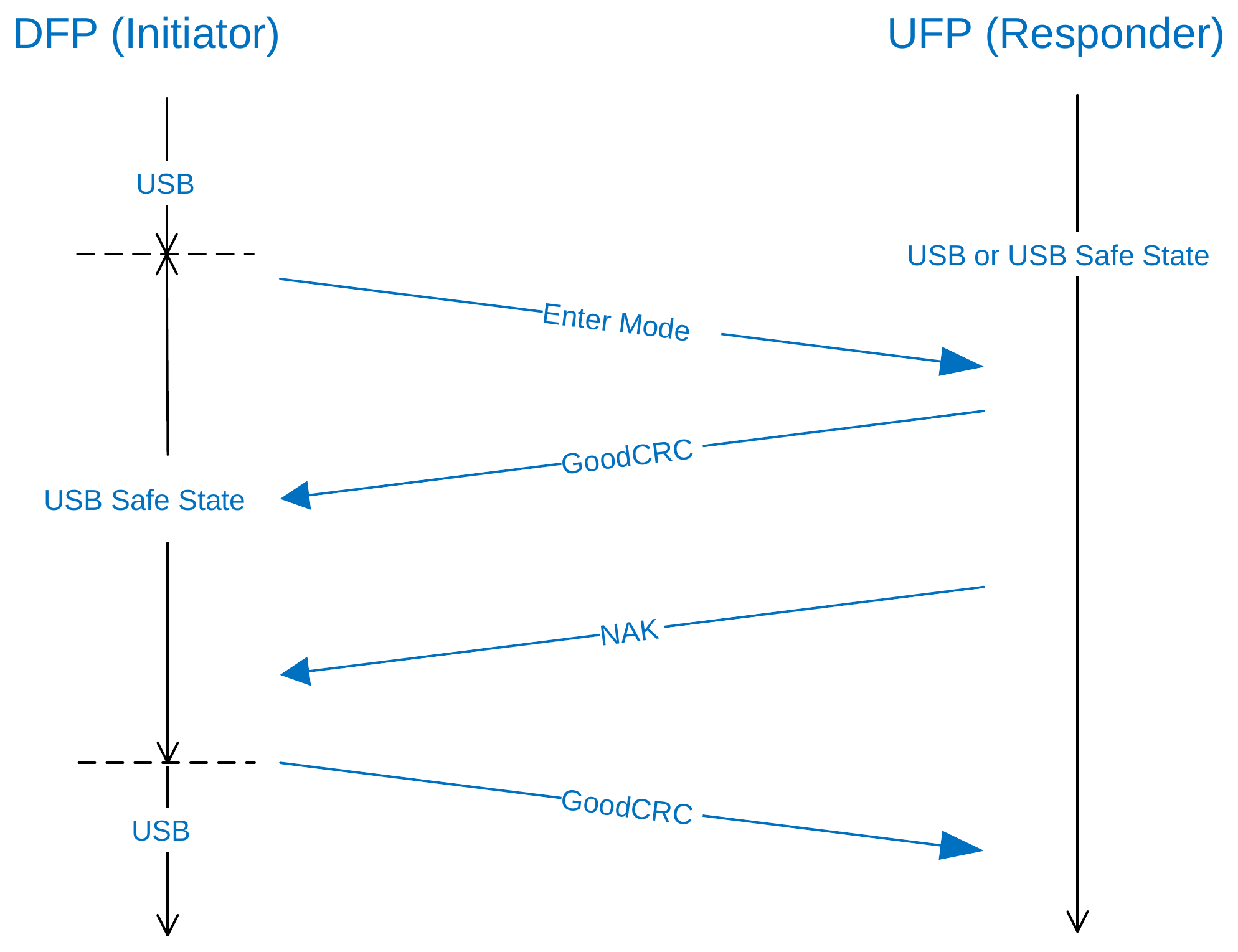
Figure 8.1 shows the sequence of events during the transition between USB operation and entering an Alternate Mode. It illustrates when the Responder's Alternate Mode changes and when the Initiator's Alternate Mode changes. Figure 8.2 illustrates that when the Responder returns a NAK the transition to an Alternate Mode does not take place and the Responder and Initiator remain in their default USB roles.
Figure 8.1. Successful Enter Mode sequence
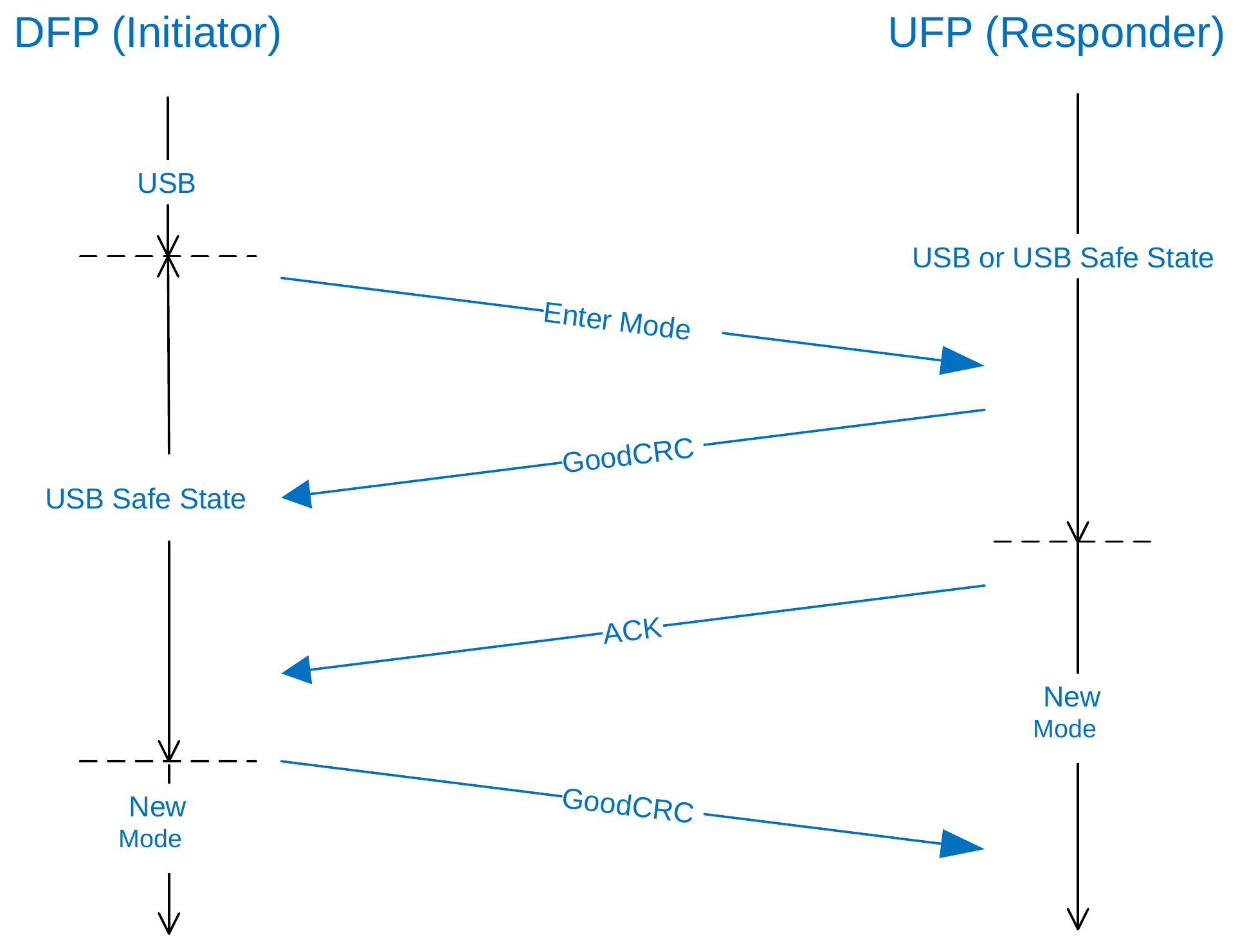
Figure 8.2. Unsuccessful Enter Mode sequence due to NAK
8.6.5. Exit Mode Command
Only the DFP Shall initiate the Exit Mode Process.
The Responder Shall exit its Active Mode before sending the response Message. The Initiator Shall exit its Active Mode when it receives the ACK. The Responder Shall Not return a BUSY acknowledgment and Shall only return a NAK acknowledgment to a Request not containing an Active Mode (i.e., Invalid object position). An Initiator which fails to receive an ACK within tVDMWaitModeExit or receives a NAK or BUSY response Shall exit its Active Mode.
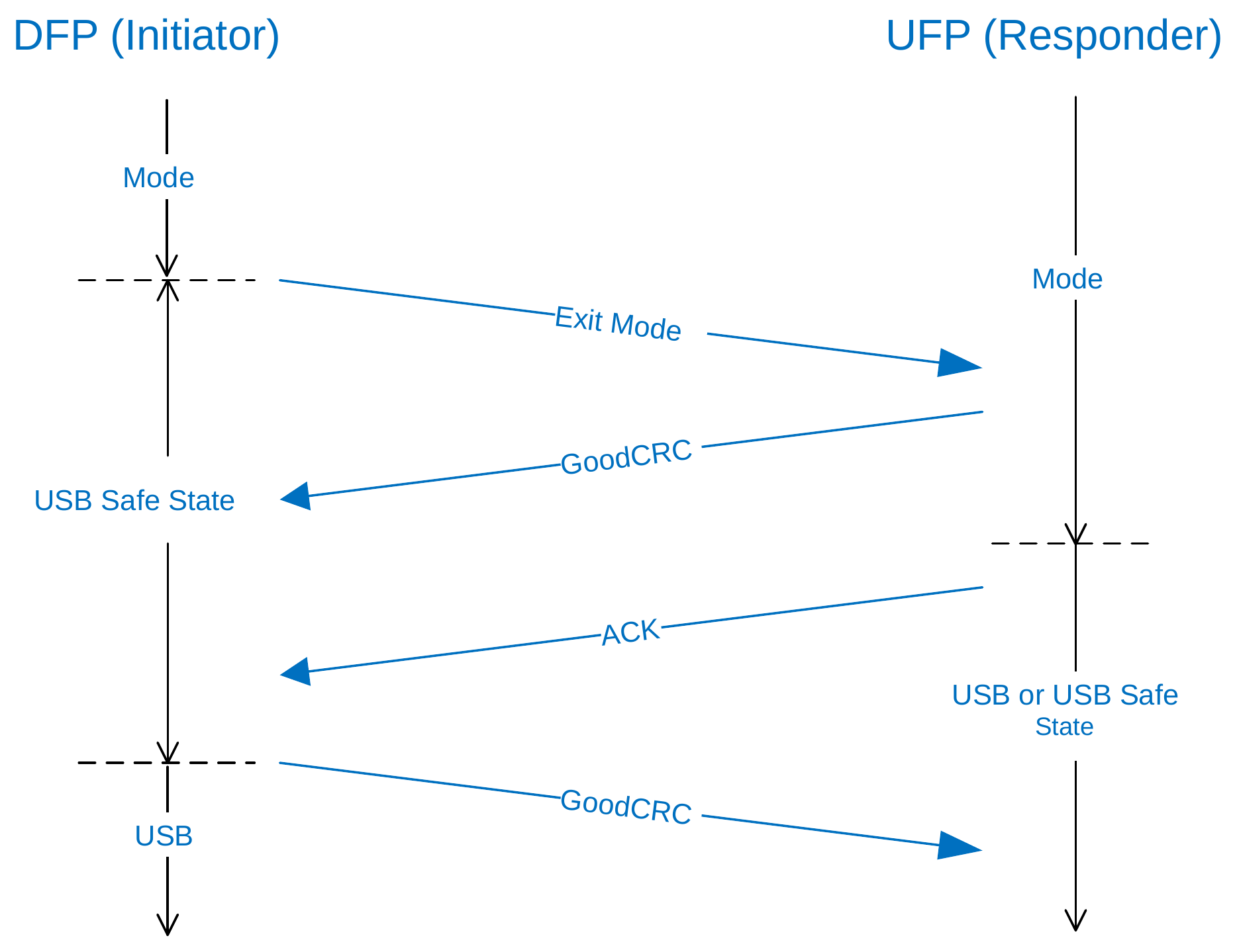
Figure 8.3, "Exit Mode sequence" shows the sequence of events during the transition between exiting an Active Mode and USB operation. It illustrates when the Responder's Alternate Mode changes and when the Initiator's Alternate Mode changes.
Figure 8.3. Exit Mode sequence
8.6.6. Attention
An Initiator May use the Attention Command to notify the Responder that it requires service.
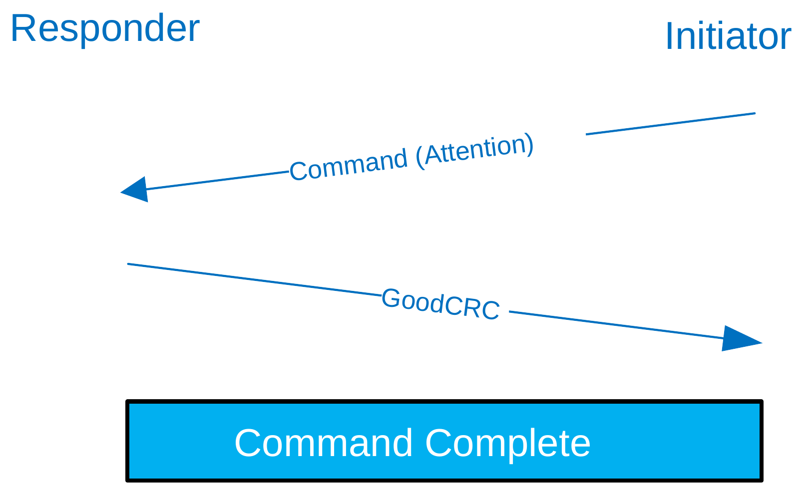
A Structured VDM Attention AMS consists of a Command Request but no Command response. A Structured VDM Attention AMS is deemed to be completed when the GoodCRC Message has been successfully received by the Initiator in reply to its Attention Command Request.
Figure 8.4. Attention Command Request/response sequence
If Structured VDMs are supported, then no response Shall be made to an Attention Command.
If Structured VDMs are supported, but the Structured VDM Attention Command Request is an Unrecognized Message it Shall be Ignored (see Table 8.1).
8.7. Command Processes
8.7.1. Discovery Process
The Discovery Process has several phases. A Port Shall complete the Discovery Process to the extent that it requires the information contained in each Message for its normal operation. However, in each phase, if the Responder does not respond with GoodCRC Message or responds with an SVDM of Command Type NAK, or with a Not_Supported Message, the Initiator Shall Not proceed to a phase of discovery contingent on the expected SVDM ACK.
8.7.1.1. Port Partner Discovery
-
The Initiator issues a
Discover IdentityREQ to determine the Responder's basic properties and Alternate Mode support. The Responder responds withDiscover IdentityACK. -
If the
Discover IdentityACK sets Modal Operation Supported = 1 in the ID Header VDO, the Responder supports at least one Alternate Mode. The Initiator issuesDiscover SVIDsREQ to determine the list of SVIDs the Responder supports. If the Responder supports six or more SVIDs, the Initiator might issue multipleDiscover SVIDsREQs. -
The Initiator sends a
Discover ModesREQ for any SVID supported by the Responder, and the Responder responds with aDiscover ModesACK containing Mode-specific information. The Initiator May initiate aDiscover ModesREQ for any or all of the Responder's supported SVIDs.
8.7.1.2. Cable Plug Discovery
The Discovery Process with the Cable Plug as Responder is substantially similar to that with the Port Partner as Responder, with the following differences:
- The Initiator must be the VCONN Source to communicate with the Cable Plugs. (See Section 7.13.)
- The Initiator Shall Not send discovery SVDM REQs to the Cable Plug at SOP''. The Initiator Shall consider any responses to discovery SVDM REQs from the Cable Plug at SOP' to apply to the Cable Plug at SOP''.
- The Initial Source/VCONN Source, if it communicates with the Cable Plug, Shall Initiate
Discover IdentityREQ to SOP' prior to the Initial Contract. (See Section 8.6.1.2.1).
8.7.2. Entering Alternate Modes
The result of the Discovery Process is that both the Initiator and Responder identify the Modes they mutually support. The Initiator (DFP), upon finding a suitable Alternate Mode, uses the Enter Mode Command to enable the Alternate Mode. Once the Alternate Mode is entered, the Device Shall remain in that Active Mode until the Exit Mode Command is successful (see Section 8.6.5 ).
A DFP May Initiate the Enter Mode Process with a Responder after it has successfully completed the Discovery Process with that Responder, subject to the specification of the Alternate Mode.
The Alternate Mode entry process with a Cable Plug as Responder is substantially similar to that with the Port Partner as Responder, with the following differences:
- The Initiator must be the VCONN Source to communicate with the Cable Plugs. (See Section 7.13.)
- The specification for each Alternate Mode determines whether the DFP must complete the Enter Mode process on SOP' and SOP'' and the timing of those processes relative to the Enter Mode process on SOP.
8.7.3. Exiting Alternate Modes
The Responder (UFP or Cable Plug) and Initiator continue using the Active Mode until the Active Mode is exited. Upon exiting an Alternate Mode, a Port or Cable Plug Shall exit any State entered via that Alternate Mode, including via Unstructured VDMs.
In a managed termination, using the Exit Mode Command, the Active Mode Shall be exited in a controlled manner as described in Section 8.6.5 .
An unmanaged termination is triggered by one of the following conditions:
- Data Reset
- Hard Reset
- Error Recovery
- Detach
Upon an unmanaged termination, the Ports Shall exit all Active Modes but Shall Not transition through USB Safe State; the Cable Plugs Shall exit all Active Modes. The Cable Plugs Shall Exit any Active Modes upon a Cable Reset.
Upon either type of termination, each Port Shall return to USB operation as defined in [USB-C] following an exit from an Alternate Mode.
The overall Message flow is illustrated in Figure 8.5, "Enter/Exit Mode Process".
Figure 8.5. Enter/Exit Mode Process
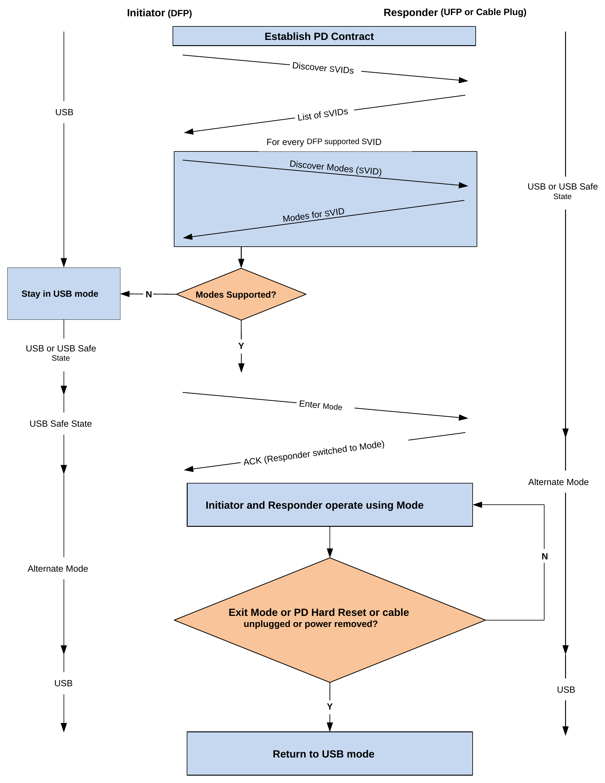
The Initiator Shall return to USB Operation within tVDMExitMode of a disconnect, of Hard Reset Signaling being detected or Error Recovery.
The Responder Shall return to either USB operation or USB Safe State within tVDMExitMode of a disconnect, of Hard Reset Signaling being detected or Error Recovery.