
219 KiB
Chapter 9. State Machine Diagrams
9.1. Protocol Layer State Diagrams
9.1.1. Introduction to Protocol Layer State Diagrams
These State diagrams define the operation of the Power Delivery Protocol Layer.
Note: These State diagrams are not intended to replace a well written and robust design.
Figure 9.1 shows an outline of the states defined in the following sections. At the top there is the name of the State. This is followed by "Actions on entry" a list of actions carried out on entering the State and in some states "Actions on exit" a list of actions carried out on exiting the State.
Figure 9.1. Outline of States
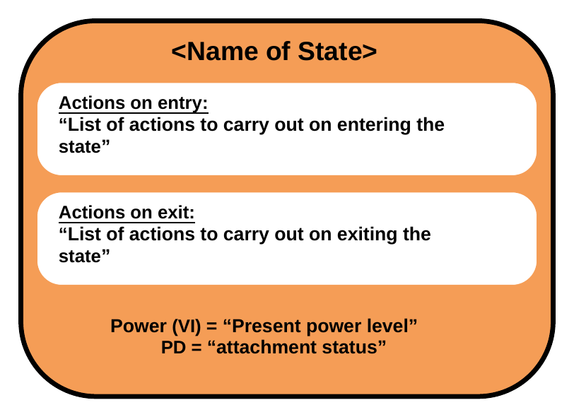
Transitions from one State to another are indicated by arrows with the conditions listed on the arrow. Where there are multiple conditions, these are Connected using either a logical OR "|" or a logical AND "&". The inverse of a condition is shown with a "NOT" in front of the condition.
In some cases, there are transitions which can occur from any State to a particular State. These are indicated by an arrow which is unconnected to a State at one end, but with the other end (the point) Connected to the final State.
In some State diagrams it is necessary to enter or exit from states in other diagrams. Figure 9.2 indicates how such references are made. The reference is indicated with a hatched box. The box contains the name of the referenced State.
Figure 9.2. References to States
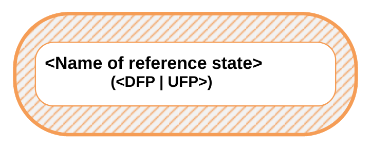
Timers are included in many of the states. Timers are initialized (set to their starting condition) and run (timer is counting) in the State it is referenced. As soon as the State is exited then the timer is no longer active. Timeouts of the timers are listed as conditions on State transitions.
Conditions listed on State transitions will come from one of three sources:
- Messages received from the PHY Layer.
- Events triggered within the Protocol Layer e.g., timer timeouts
- Message and related indications passed up to the Policy Engine from the Protocol Layer (Message sent; Message received etc.)
9.1.2. State Operation
The following section details Protocol Layer State Operation when sending and receiving SOP* Packets.
For each SOP' Communication being sent and received there Shall be separate Protocol Layer Transmission and Protocol Layer Reception and Hard Reset State Machine instances, with their own counter and timer instances. When Chunking is supported there Shall be separate Chunked Tx, Chunked Tx, and Chunked Message Router State Machine instances.
Soft Reset Shall only apply to the State Machine instances it is targeted at based on the type of SOP* Packet used to send the Soft_Reset Message. The Hard Reset State Machine (including Cable Reset) Shall apply simultaneously to all Protocol Layer State Machine instances active in the DFP, UFP and Cable Plug (if present).
9.1.2.1. Protocol Layer Chunking
9.1.2.1.1. Architecture of Device Including Chunking Layer
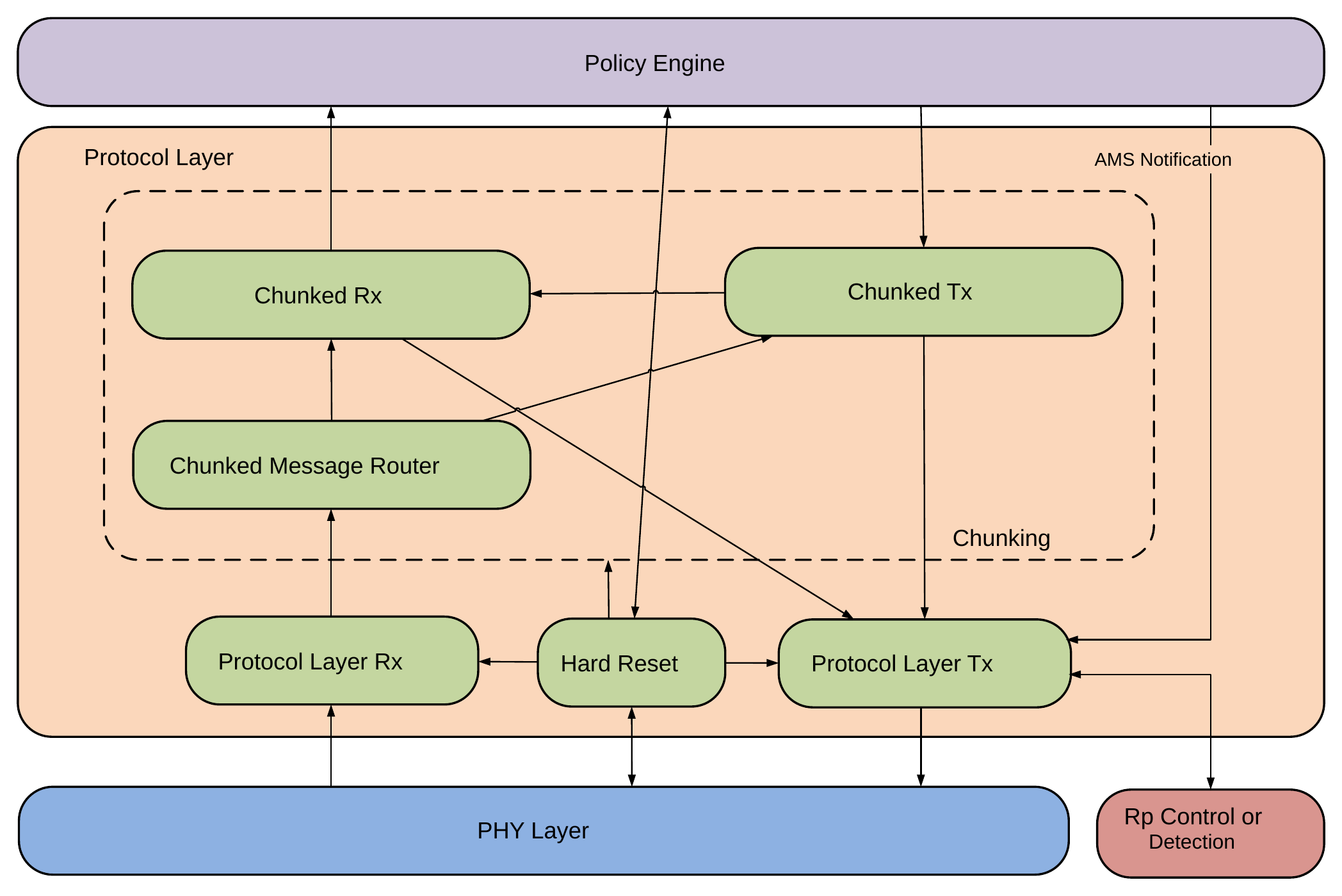
The Chunking component resides in the Protocol Layer between the Policy Engine and Protocol Tx/Rx. Figure 9.3 illustrates the relationship between components.
The Chunking Layer comprises three related State machines:
- Chunked Rx.
- Chunked Tx.
- Chunked Message Router.
Note: The consequence of this architecture is that the Policy Engine deals entirely in Unchunked Messages. It will not receive (and might not respond to) a Message until all the related chunks have been collated.
If a PD Device or Cable Plug has no requirement to handle any Message requiring more than one Chunk of any Extended Message, it May omit the Chunking Layer. In this case it Shall implement the ChunkingNotSupportedTimer to ensure compatible operation with partners which support Chunking (see Section 7.31.15.1 and Section 9.2.7 ).
Figure 9.3. Chunking architecture Showing Message and Control Flow
9.1.2.1.1.1. Abort Mechanism
Long Chunked Messages bring with them the potential problem that they could prevent urgent Messages from being transmitted in a timely manner. An Optional Abort mechanism is provided to remedy this problem.
The Abort Flag referred to in the diagrams below May be set and examined by the Policy Engine. The specific means are left to the implementer.
9.1.2.1.1.2. Aborting Sending a Long-Chunked Message
A long-Chunked Message being sent May be aborted by setting the Abort Flag. The Message Shall be considered aborted when the Abort Flag is again cleared by the Chunked Tx State machine.
9.1.2.1.1.3. Aborting Receiving a Long-Chunked Message
If the Abort mechanism has been implemented, any Message sent while a Chunked Message receive is in progress will result in an error report being received by the Policy Engine, to indicate that the Message Request has been Discarded. If the Message was urgent the Policy Engine might set the Abort Flag, which will result in the incoming Chunked Message being aborted. The Abort Flag being cleared by the Chunked Rx State machine indicates that the urgent Message can now be sent.
9.1.2.1.2. Chunked Rx State Diagram
Figure 9.4 shows the State behavior for the Chunked Rx State Machine. This recognizes whether Chunked received Messages are involved and deals with requesting chunks when they are. It also performs validity checks on all Messages related to Chunking.
Figure 9.4. Chunked Rx State Diagram
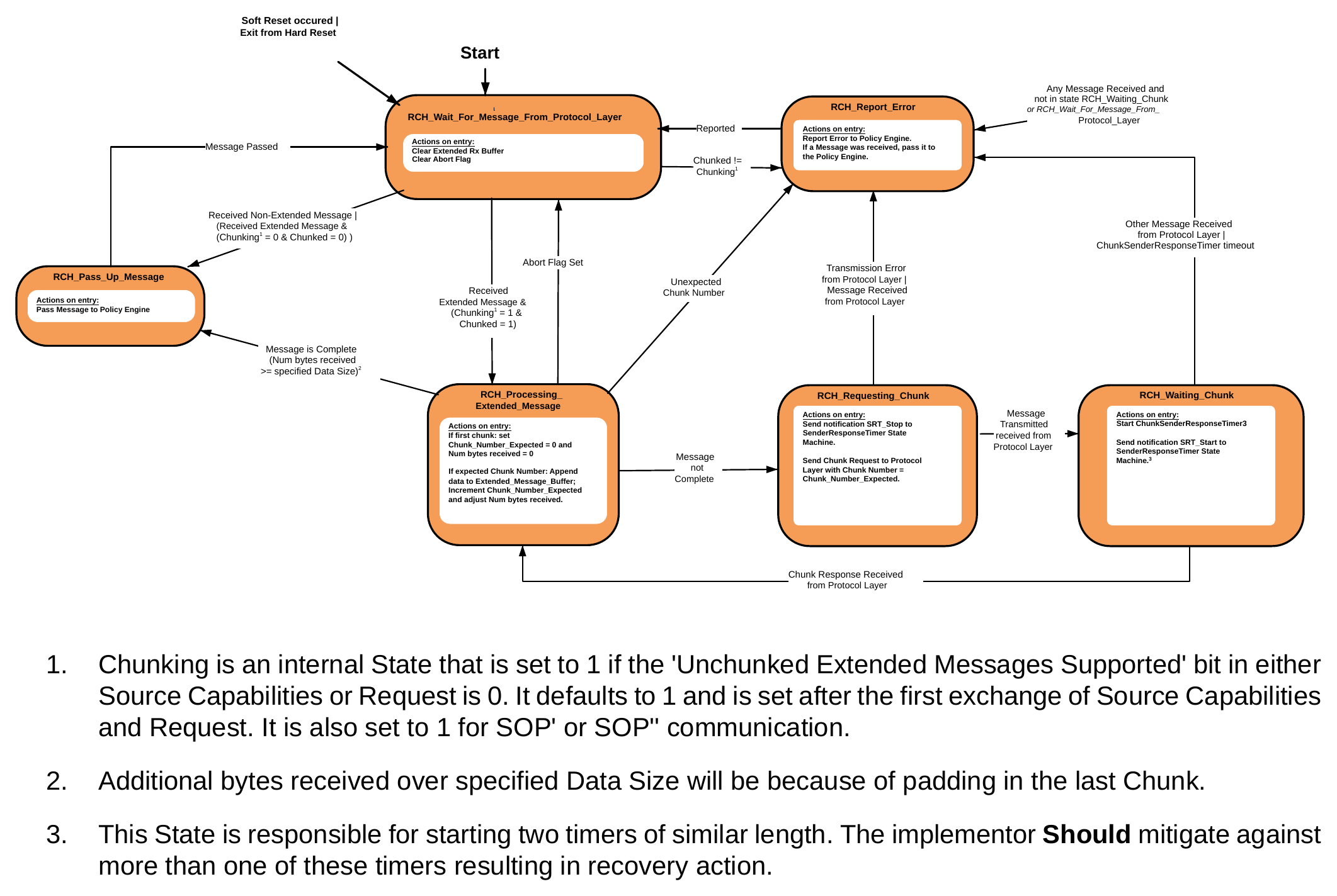
- Chunking is an internal State that is set to 1 if the 'Unchunked Extended Messages Supported' bit in either Source Capabilities or Request is 0. It defaults to 1 and is set after the first exchange of Source Capabilities and Request. It is also set to 1 for SOP' or SOP'' communication.
- Additional bytes received over specified Data Size will be because of padding in the last Chunk.
- This State is responsible for starting two timers of similar length. The implementor Should mitigate against more than one of these timers resulting in recovery action.
9.1.2.1.2.1. RCH_Wait_For_Message_From_Protocol_Layer State
The Chunked Rx State Machine Shall enter the RCH_Wait_For_Message_From_Protocol_Layer State:
- At startup.
- As a result of a Soft Reset occurring.
- On exit from a Hard Reset.
On entry to the RCH_Wait_For_Message_From_Protocol_Layer State the Chunked Rx State machine clears the Extended Rx Buffer and clears the Abort Flag.
In the RCH_Wait_For_Message_From_Protocol_Layer State the Chunked Rx State machine waits until the Chunked Message Router passes up a received Message.
The Chunked Rx State Machine Shall transition to the RCH_Pass_Up_Message State when:
- A non-Extended Message is passed up from the Chunked Message Router.
- An Extended Message is passed up from the Chunked Message Router, and the Policy Engine has determined that we are not doing Chunking, and the Message has its Chunked bit set to 0b.
The Chunked Rx State Machine Shall transition to the RCH_Processing_Extended_Message State when:
- An Extended Message is passed up from the Chunked Message Router, and the Policy Engine has determined that we are doing Chunking, and the Message has its Chunked bit set to 1b.
9.1.2.1.2.2. RCH_Pass_Up_Message State
On entry to the RCH_Pass_Up_Message State the Chunked Rx State machine Shall pass the received Message to the Policy Engine.
The Chunked Rx State Machine Shall transition to the RCH_Wait_For_Message_From_Protocol_Layer State when:
- The Message has been passed.
9.1.2.1.2.3. RCH_Processing_Extended_Message State
On entry to the RCH_Processing_Extended_Message State the Chunked Rx State machine Shall:
- If this is the first Chunk:
- Set Chunk_Number_Expected = 0.
- Set Num bytes received = 0.
- If Chunk contains the expected Chunk Number:
- Append its data to the Extended_Message_Buffer.
- Increment Chunk_Number_Expected.
- Adjust Num bytes received.
The Chunked Rx State Machine Shall transition to the RCH_Pass_Up_Message State when:
- The Message is complete (i.e., Num bytes received ≥ specified Data Size.
Note: The inequality allows for padding bytes in the last Chunk, which are not actually part of the Extended Message).
The Chunked Rx State Machine Shall transition to the RCH_Requesting_Chunk State when:
- The Message is not yet complete.
The Chunked Rx State Machine Shall transition to the RCH_Report_Error State when:
- An unexpected Chunk Number is received.
The Chunked Rx State Machine Shall transition to the RCH_Wait_For_Message_From_Protocol_Layer State when:
- The Abort Flag is set.
9.1.2.1.2.4. RCH_Requesting_Chunk State
On entry to the RCH_Requesting_Chunk State the Chunked Rx State machine Shall:
- Send notification SRT_Stop to SenderResponseTimer State machine (see Section 9.2.2 ).
- Send Chunk Request to Protocol Layer with Chunk Number = Chunk_Number_Expected. The Chunked Rx State Machine Shall transition to the RCH_Waiting_Chunk State when:
- Message Transmitted is received from the Protocol Layer.
The Chunked Rx State Machine Shall transition to the RCH_Report_Error State when:
- Transmission Error is received from the Protocol Layer, or
- A Message is received from the Protocol Layer.
9.1.2.1.2.5. RCH_Waiting_Chunk State
On entry to the RCH_Waiting_Chunk State the Chunked Rx State machine Shall:
- Start the ChunkSenderResponseTimer.
- Send notification SRT_Start to SenderResponseTimer State machine (see Section 9.2.2).
The Chunked Rx State Machine Shall transition to the RCH_Processing_Extended_Message State when:
- A Chunk is received from the Protocol Layer.
The Chunked Rx State Machine Shall transition to the RCH_Report_Error State when:
- A Message, other than a Chunk, is received from the Protocol Layer, or
- The ChunkSenderResponseTimer expires.
9.1.2.1.2.6. RCH_Report_Error State
The Chunked Rx State Machine Shall enter the RCH_Report_Error State:
- When any Message is received and the Chunked Rx State Machine is not in one of the states RCH_Waiting_Chunk or RCH_Wait_For_Message_From_Protocol_Layer.
On entry to the RCH_Report_Error State the Chunked Rx State machine Shall:
- Report the error to the Policy Engine.
- If the State was entered because a Message was received, this Message Shall be passed to the Policy Engine.
The Chunked Rx State Machine Shall transition to the RCH_Wait_For_Message_From_Protocol_Layer State when:
- The error has been reported.
- Any Message received was passed to the Policy Engine.
9.1.2.1.3. Chunked Tx State Diagram
- Figure 9.5 shows the State behavior for the Chunked Tx State Machine. This recognizes whether Chunked transmitted Messages are involved and deals with sending chunks and waiting for Chunk requests when they are. It also performs validity checks on all related Messages related to Chunking.
Figure 9.5. Chunked Tx State Diagram
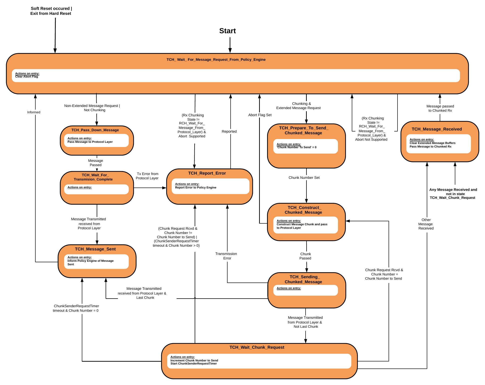
9.1.2.1.3.1. TCH_Wait_For_Message_Request_From_Policy_Engine State
The Chunked Tx State Machine Shall enter the TCH_Wait_For_Message_Request_From_Policy_Engine State:
- At startup.
- As a result of a Soft Reset occurring.
- On exit from a Hard Reset.
On entry to the TCH_Wait_For_Message_Request_From_Policy_Engine State the Chunked Tx State machine clears the Abort Flag.
In the TCH_Wait_For_Message_Request_From_Policy_Engine State the Chunked Tx State Machine waits until the Policy Engine sends it a Message Request.
The Chunked Tx State Machine Shall transition to the TCH_Pass_Down_Message State when:
- A non-Extended Message Request is received from the Policy Engine, or
- A Message Request is received from the Policy Engine and the link is not Chunking.
The Chunked Tx State Machine Shall transition to the TCH_Prepare_To_Send_Chunked_Message State when:
- An Extended Message Request is received from the Policy Engine, and the link is Chunking.
The Chunked Tx State Machine Shall Discard the Message Request and remain in the TCH_Wait_For_Message_Request_From_Policy_Engine State when:
- The Chunked Rx State is any other than RCH_Wait_For_Message_From_Protocol_Layer, and the Abort Flag has not been implemented.
The Chunked Tx State Machine Shall Discard the Message Request and enter the TCH_Report_Error State when:
- The Chunked Rx State is any other than RCH_Wait_For_Message_From_Protocol_Layer and the Abort Flag has been implemented.
9.1.2.1.3.2. TCH_Pass_Down_Message State
On entry to the TCH_Pass_Down_Message State the Chunked Tx State Machine Shall pass the Message to the Protocol Layer.
The Chunked Tx State Machine Shall transition to the TCH_Wait_For_Transmision_Complete State when:
- The Message has been passed to the Protocol Layer.
9.1.2.1.3.3. TCH_Wait_For_Transmision_Complete State
The Chunked Tx State Machine Shall transition to the TCH_Message_Sent State when:
- Message Transmitted has been received from the Protocol Layer.
The Chunked Tx State Machine Shall transition to the TCH_Report_Error State when:
- Transmission Error has been received from the Protocol Layer.
9.1.2.1.3.4. TCH_Message_Sent State
On entry to the TCH_Message_Sent State the Chunked Tx State Machine Shall:
- Inform the Policy Engine that the Message has been sent.
The Chunked Tx State Machine Shall transition to the TCH_Wait_For_Message_Request_From_Policy_Engine State when:
- The Policy Engine has been informed.
9.1.2.1.3.5. TCH_Prepare_To_Send_Chunked_Message State
On entry to the TCH_Prepare_To_Send_Chunked_Message State the Chunked Tx State Machine Shall:
- Set 'Chunk Number To Send' to zero.
The Chunked Tx State Machine Shall transition to the TCH_Construct_Chunked_Message State when:
- 'Chunk Number To Send' has been set to zero.
9.1.2.1.3.6. TCH_Construct_Chunked_Message State
On entry to the TCH_Construct_Chunked_Message State the Chunked Tx State Machine Shall:
- Construct a Message Chunk and pass it to the Protocol Layer.
The Chunked Tx State Machine Shall transition to the TCH_Sending_Chunked_Message State when:
- The Message Chunk has been passed to the Protocol Layer.
The Chunked Tx State Machine Shall transition to the TCH_Wait_For_Message_Request_From_Policy_Engine State when:
- The Abort Flag is set.
9.1.2.1.3.7. TCH_Sending_Chunked_Message State
The Chunked Tx State Machine Shall transition to the TCH_Wait_Chunk_Request State when:
- Message Transmitted is received from Protocol Layer and this was the last Chunk.
The Chunked Tx State Machine Shall transition to the TCH_Message_Sent State when:
- Message Transmitted is received from Protocol Layer and this was the last Chunk.
The Chunked Tx State Machine Shall transition to the TCH_Report_Error State when:
- Transmission Error has been received from the Protocol Layer.
9.1.2.1.3.8. TCH_Wait_Chunk_Request State
On entry to the TCH_Wait_Chunk_Request State the Chunked Tx State Machine Shall:
- Increment Chunk Number to Send.
- Start ChunkSenderRequestTimer.
The Chunked Tx State Machine Shall transition to the TCH_Report_Error State when:
- A Chunk Request has been received and the Chunk Number does not equal Chunk Number to Send or
- ChunkSenderRequestTimer has expired and Chunk Number is greater than zero.
The Chunked Tx State Machine Shall transition to the TCH_Message_Sent State when:
- ChunkSenderRequestTimer has expired and Chunk Number equals zero.
Note: This is the mechanism which allows the remote Port Partner or Cable Plug to omit the Chunking Layer. The Policy Engine will receive a Message Sent signal if the remote Port Partner or Cable Plug is present (GoodCRC Message received) but does not send a Chunk Request. After this the remote Port Partner will send a Not_Supported Message, or the Cable Plug will Ignore the Chunked Message.
The Chunked Tx State Machine Shall transition to the TCH_Message_Received State when:
- Any other Message than Chunk Request is received.
9.1.2.1.3.9. TCH_Message_Received State
The Chunked Tx State Machine Shall enter the TCH_Message_Received State:
- When any Message is received, and the Chunked Tx State Machine is not in the TCH_Wait_Chunk_Request State.
On entry to the TCH_Message_Received State the Chunked Tx State Machine Shall:
- Clear the Extended Message Buffers.
- Pass the received Message to Chunked Rx Engine.
The Chunked Tx State Machine Shall transition to the TCH_Wait_For_Message_Request_From_Policy_Engine State when:
- The received Message has been passed to the Chunked Rx Engine.
9.1.2.1.3.10. TCH_Report_Error State
On entry to the TCH_Report_Error State the Chunked Tx State Machine Shall:
- Report the error to the Policy Engine.
The Chunked Tx State Machine Shall transition to the TCH_Wait_For_Message_Request_From_Policy_Engine State when:
- The error has been reported.
9.1.2.1.4. Chunked Message Router State Diagram
Figure 9.6 shows the State behavior for the Chunked Message Router. This determines to which State machine an incoming Message is routed to (Chunked Rx, Chunked Tx or direct to Policy Engine).
Figure 9.6. Chunked Message Router State Diagram
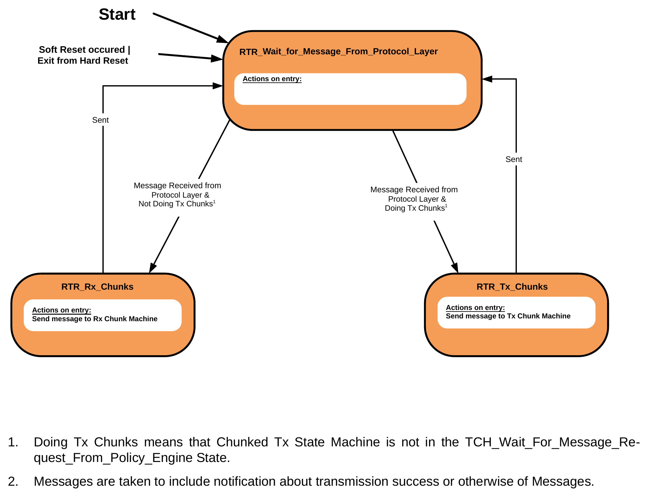
- Doing Tx Chunks means that Chunked Tx State Machine is not in the TCH_Wait_For_Message_Request_From_Policy_Engine State.
- Messages are taken to include notification about transmission success or otherwise of Messages.
9.1.2.1.4.1. RTR_Wait_for_Message_From_Protocol_Layer State
In the RTR_Wait_for_Message_From_Protocol_Layer State the Chunked Message Router waits until the Protocol Layer sends it a received Message.
The Chunked Message Router Shall transition to the RTR_Rx_Chunks State when:
-
A Message is received from the Protocol Layer, and the combined Chunking is not doing Tx Chunks. The Chunked Message Router Shall transition to the RTR_Tx_Chunks State when:
-
A Message is received from the Protocol Layer, and the combined Chunking is doing Tx Chunks.
9.1.2.1.4.2. RTR_Rx_Chunks State
On entry to the RTR_Rx_Chunks State the Chunked Message Router Shall:
- Send the Message to the Chunked Rx State Machine.
- Transition to the RTR_Wait_for_Message_From_Protocol_Layer State.
9.1.2.1.4.3. RTR_Tx_Chunks State
On entry to the RTR_Tx_Chunks State the Chunked Message Router Shall:
- Send the Message to the Chunked Tx State Machine.
- Transition to the RTR_Wait_for_Message_From_Protocol_Layer State.
9.1.2.2. Protocol Layer Message Transmission
9.1.2.2.1. Common Protocol Layer Message Transmission State Diagram
Figure 9.7 shows the State behavior, common between the Source and the Sink, for the Protocol Layer when transmitting a Message.
Figure 9.7. Common Protocol Layer Message Transmission State Diagram
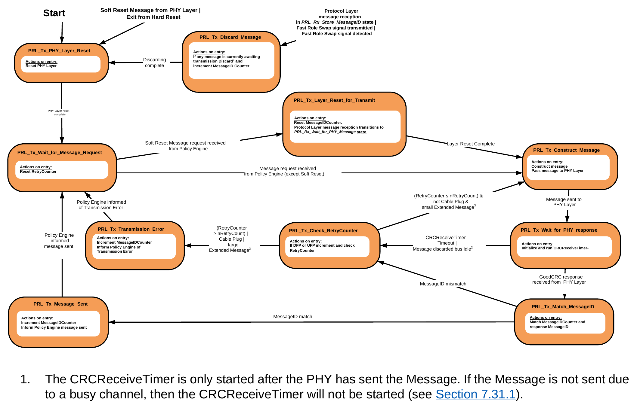
- The CRCReceiveTimer is only started after the PHY has sent the Message. If the Message is not sent due to a busy channel, then the CRCReceiveTimer will not be started (see Section 7.31.1).
- This indication is sent by the PHY Layer when a Message has been Discarded due to CC being busy, and after CC becomes Idle again (see Section 5.2.2). The CRCReceiveTimer is not running in this case since no Message has been sent.
- A "small" Extended Message is either an Extended Message with Data Size ≤ MaxExtendedMsgLegacyLen bytes or an Extended Message with Data Size > MaxExtendedMsgLegacyLen bytes that has been Chunked. A "large" Extended Message is an Extended Message with Data Size > MaxExtendedMsgLegacyLen bytes that has not been Chunked.
- See Section 7.3 for details of when Messages are Discarded.
9.1.2.2.1.1. PRL_Tx_PHY_Layer_Reset State
The Protocol Layer Shall enter the PRL_Tx_PHY_Layer_Reset State:
- At startup.
- As a result of a Soft Reset Request being received by the PHY Layer.
- On exit from a Hard Reset.
On entry to the PRL_Tx_PHY_Layer_Reset State the Protocol Layer Shall reset the PHY Layer (clear any outstanding messages and enable communications).
The Protocol Layer Shall transition to the PRL_Tx_Wait_for_Message_Request State when:
- When the PHY Layer reset is complete.
9.1.2.2.1.2. PRL_Tx_Wait_for_Message_Request State
In the PRL_Tx_Wait_for_Message_Request State the Protocol Layer waits until the Policy Engine directs it to send a Message.
- On entry to the PRL_Tx_Wait_for_Message_Request State the Protocol Layer Shall reset the RetryCounter.
The Protocol Layer Shall transition to the PRL_Tx_Construct_Message State when:
-
A Message Request is received from the Policy Engine which is not a Soft_Reset Message. The Protocol Layer Shall transition to the PRL_Tx_Layer_Reset_for_Transmit State when:
-
A Message Request is received from the Policy Engine which is a Soft_Reset Message.
9.1.2.2.1.3. PRL_Tx_Layer_Reset_for_Transmit State
On entry to the PRL_Tx_Layer_Reset_for_Transmit State the Protocol Layer Shall reset the MessageIDCounter. The Protocol Layer Shall transition Protocol Layer Message reception to the PRL_Rx_Wait_for_PHY_Message State (see Section 9.1.2.3.1 ) in order to reset the stored MessageID.
The Protocol Layer Shall transition to the PRL_Tx_Construct_Message State when:
- The layer reset actions in this State have been completed.
9.1.2.2.1.4. PRL_Tx_Construct_Message State
On entry to the PRL_Tx_Construct_Message State the Protocol Layer Shall construct the Message requested by the Policy Engine, or resend a previously constructed Message, and then pass this Message to the PHY Layer. The Protocol Layer Shall transition to the PRL_Tx_Wait_for_PHY_Response State when:
- The Message has been sent to the PHY Layer.
9.1.2.2.1.5. PRL_Tx_Wait_for_PHY_Response State
On entry to the PRL_Tx_Wait_for_PHY_Response State, once the Message has been sent, the Protocol Layer Shall initialize and run the CRCReceiveTimer (see Section 7.31.1). The Protocol Layer Shall transition to the PRL_Tx_Match_MessageID State when:
- A GoodCRC Message response is received from the PHY Layer.
The Protocol Layer Shall transition to the PRL_Tx_Check_RetryCounter State when:
- The CRCReceiveTimer times out.
- Or the PHY Layer indicates that a Message has been Discarded due to the channel being busy but the channel is now Idle (see Section 5.2.2).
9.1.2.2.1.6. PRL_Tx_Match_MessageID State
On entry to the PRL_Tx_Match_MessageID State the Protocol Layer Shall compare the MessageIDCounter and the MessageID of the received GoodCRC Message.
The Protocol Layer Shall transition to the PRL_Tx_Message_Sent State when:
-
The MessageIDCounter and the MessageID of the received GoodCRC Message match. The Protocol Layer Shall transition to the PRL_Tx_Check_RetryCounter State when:
-
The MessageIDCounter and the MessageID of the received GoodCRC Message do not match.
9.1.2.2.1.7. PRL_Tx_Message_Sent State
On entry to the PRL_Tx_Message_Sent State the Protocol Layer Shall increment the MessageIDCounter and inform the Policy Engine that the Message has been sent.
The Protocol Layer Shall transition to the PRL_Tx_Wait_for_Message_Request State when:
- The Policy Engine has been informed that the Message has been sent.
9.1.2.2.1.8. PRL_Tx_Check_RetryCounter State
On entry to the PRL_Tx_Check_RetryCounter State the Protocol Layer in a DFP or UFP Shall increment the value of the RetryCounter and then check it in order to determine whether it is necessary to retry sending the Message.
Note: Cable Plugs do not retry Messages and so do not use the RetryCounter.
The Protocol Layer Shall transition to the PRL_Tx_Construct_Message State in order to retry Message sending when:
- RetryCounter ≤ nRetryCount and
- This is not a Cable Plug and
- This is an Extended Message with Data Size ≤ MaxExtendedMsgLegacyLen or
- This is an Extended Message that has been Chunked.
The Protocol Layer Shall transition to the PRL_Tx_Transmission_Error State when:
- RetryCounter > nRetryCount or
- This is a Cable Plug, which does not retry.
- This is an Extended Message with Data Size > MaxExtendedMsgLegacyLen that has not been Chunked.
9.1.2.2.1.9. PRL_Tx_Transmission_Error State
On entry to the PRL_Tx_Transmission_Error State the Protocol Layer Shall increment the MessageIDCounter and inform the Policy Engine of the transmission error.
The Protocol Layer Shall transition to the PRL_Tx_Wait_for_Message_Request State when:
- The Policy Engine has been informed of the transmission error.
PRL_Tx_Discard_Message State
Protocol Layer Message transmission Shall enter the PRL_Tx_Discard_Message State whenever:
- Protocol Layer Message reception receives an incoming Message or
- The Fast Role Swap Request is being transmitted (see Section 10.3 )
- The Fast Role Swap Request is detected (see Section 10.3).
On entry to the PRL_Tx_Discard_Message State, if there is a Message queued awaiting transmission, the Protocol Layer Shall Discard the Message according to the rules in Section 5.2.2 and increment the MessageIDCounter.
The Protocol Layer Shall transition to the PRL_Tx_PHY_Layer_Reset State when:
- Discarding is complete i.e., the Message queue is empty.
9.1.2.2.2. Source Protocol Layer Message Transmission State Diagram
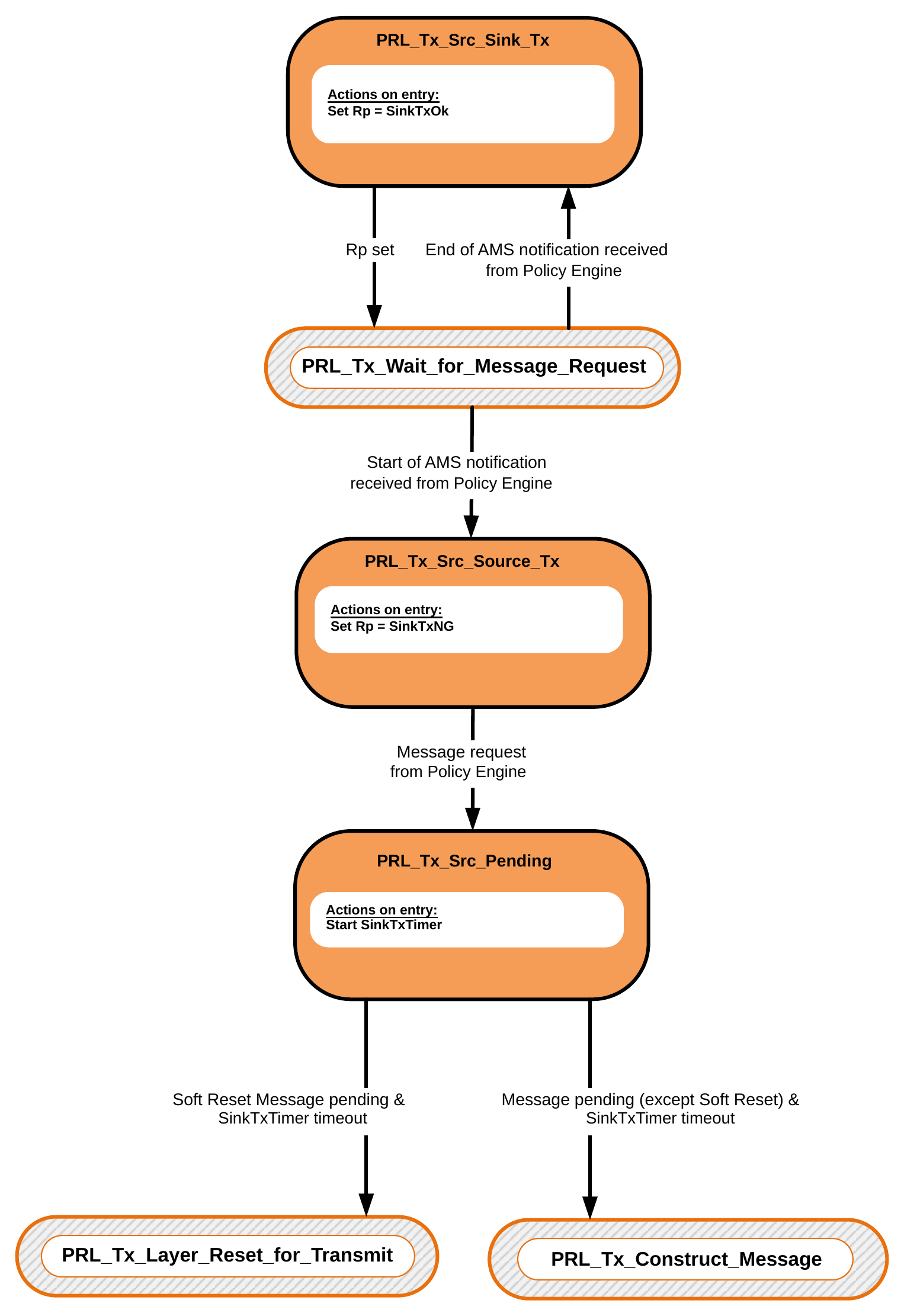
Figure 9.8 shows the State behavior for the Protocol Layer in a Source when transmitting a Message.
Figure 9.8. Source Protocol Layer Message Transmission State Diagram
9.1.2.2.2.1. PRL_Tx_Src_Sink_Tx State
In the PRL_Tx_Src_Sink_Tx State the Source sets Rp to SinkTxOK allowing the Sink to start an Atomic Message Sequence (AMS). The Protocol Layer in a Source Shall transition from the PRL_Tx_Wait_for_Message_Request State to the PRL_Tx_Src_Sink_Tx State when:
- A notification is received from the Policy Engine that the end of an AMS has been reached.
On entry to the PRL_Tx_Src_Sink_Tx State the Protocol Layer Shall Request the PHY Layer to Rp to SinkTxOK. The Protocol Layer Shall transition to the PRL_Tx_Wait_for_Message_Request State when:
- Rp has been set.
9.1.2.2.2.2. PRL_Tx_Src_Source_Tx State
In the PRL_Tx_Src_Source_Tx State the Source sets Rp to SinkTxNG allowing the Source to start an Atomic Message Sequence (AMS). The Protocol Layer in a Source Shall transition from the PRL_Tx_Wait_for_Message_Request State to the PRL_Tx_Src_Source_Tx State when:
- A notification is received from the Policy Engine that an AMS will be starting.
On entry to the PRL_Tx_Src_Source_Tx State the Protocol Layer Shall set Rp to SinkTxNG. The Protocol Layer Shall transition to the PRL_Tx_Src_Pending State when:
- A Message Request is received from the Policy Engine.
9.1.2.2.2.3. PRL_Tx_Src_Pending State
In the PRL_Tx_Src_Pending State the Protocol Layer has a Message buffered ready for transmission. On entry to the PRL_Tx_Src_Pending State the SinkTxTimer Shall be initialized and run.
The Protocol Layer Shall transition to the PRL_Tx_Construct_Message State when:
- The pending Message Request from the Policy Engine is not a Soft_Reset Message and
- The SinkTxTimer times out.
The Protocol Layer Shall transition to the PRL_Tx_Layer_Reset_for_Transmit State when:
- The pending Message Request from the Policy Engine is a Soft_Reset Message and
- The SinkTxTimer times out.
9.1.2.2.3. Sink Protocol Layer Message Transmission State Diagram
Figure 9.9 shows the State behavior for the Protocol Layer in a Sink when transmitting a Message.
Figure 9.9. Sink Protocol Layer Message Transmission State Diagram
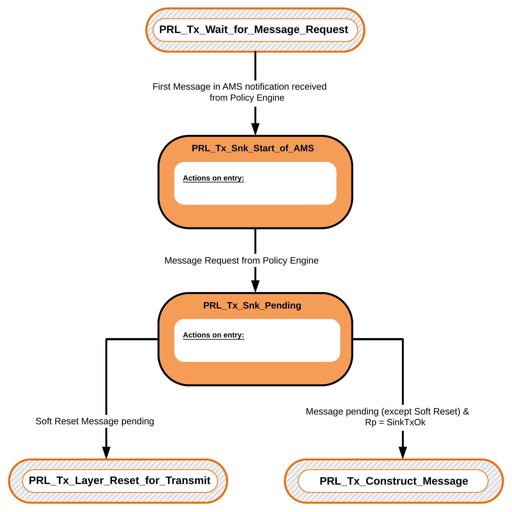
9.1.2.2.3.1. PRL_Tx_Snk_Start_of_AMS State
In the PRL_Tx_Snk_Start_of_AMS State the Protocol Layer waits for the first Message in a Sink initiated AMS. The Protocol Layer in a Sink Shall transition from the PRL_Tx_Wait_for_Message_Request State to the PRL_Tx_Snk_Start_of_AMS State when:
- A notification is received from the Policy Engine that the next Message the Sink will send is the start of an AMS.
The Protocol Layer Shall transition to the PRL_Tx_Snk_Pending State when:
- A Message Request is received from the Policy Engine.
9.1.2.2.3.2. PRL_Tx_Snk_Pending State
In the PRL_Tx_Snk_Pending State the Protocol Layer has the first Message in a Sink initiated AMS ready to send and is waiting for Rp to transition to SinkTxOK before sending the Message.
The Protocol Layer Shall transition to the PRL_Tx_Construct_Message State when:
- A Message is Pending that is not a Soft_Reset Message and
- Rp is set to SinkTxOK.
The Protocol Layer Shall transition to the PRL_Tx_Layer_Reset_for_Transmit State when:
- A Soft_Reset Message is pending.
9.1.2.3. Protocol Layer Message Reception
Figure 9.10 shows the State behavior for the Protocol Layer when receiving a Message.
Figure 9.10. Protocol Layer Message reception
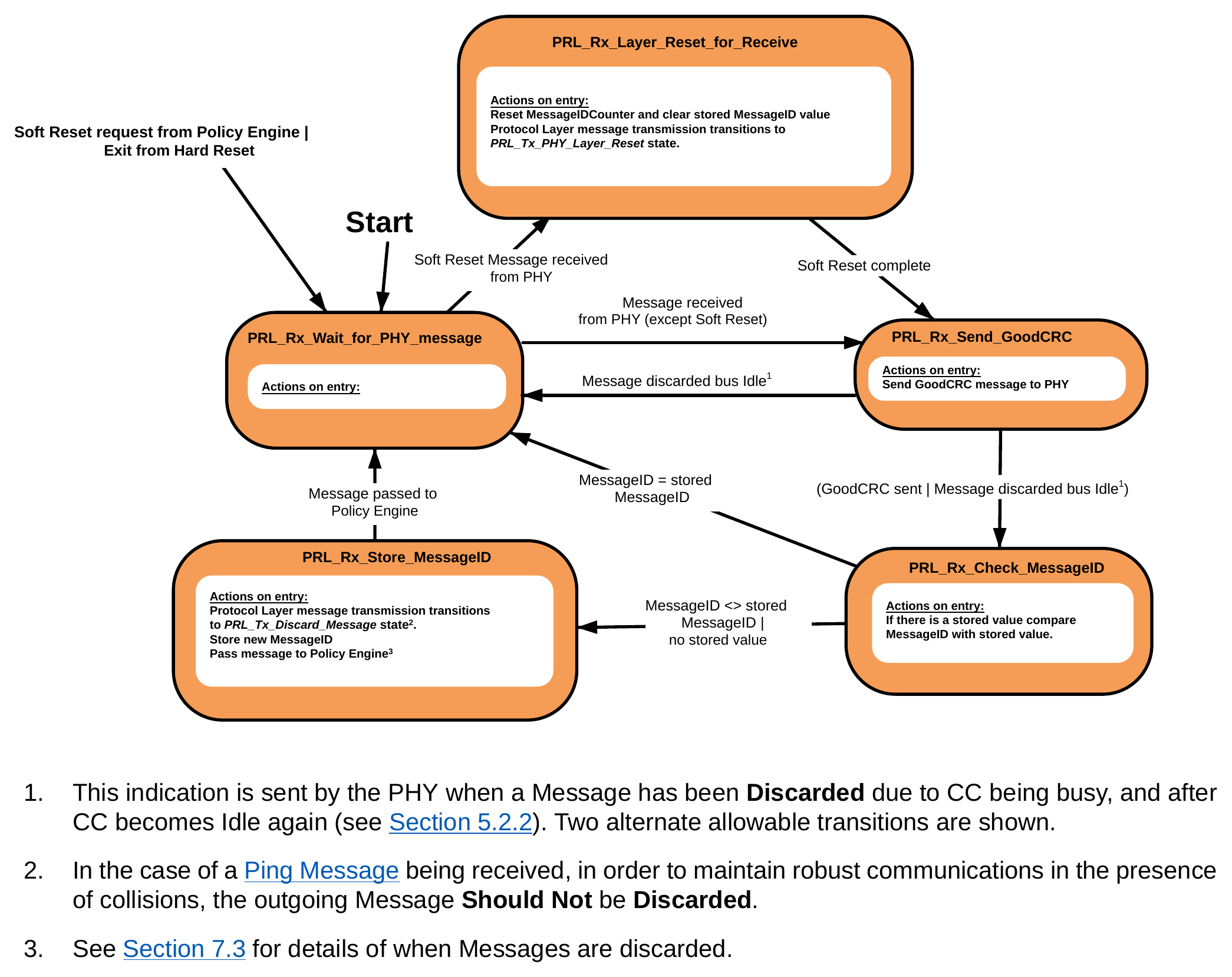
- This indication is sent by the PHY when a Message has been Discarded due to CC being busy, and after CC becomes Idle again (see Section 5.2.2). Two alternate allowable transitions are shown.
- In the case of a Ping Message being received, in order to maintain robust communications in the presence of collisions, the outgoing Message Should Not be Discarded.
- See Section 7.3 for details of when Messages are discarded.
9.1.2.3.1. PRL_Rx_Wait_for_PHY_Message State
The Protocol Layer Shall enter the PRL_Rx_Wait_for_PHY_Message State:
- At startup.
- As a result of a Soft Reset Request from the Policy Engine.
- On exit from a Hard Reset.
In the PRL_Rx_Wait_for_PHY_Message State the Protocol Layer waits until the PHY Layer passes up a received Message.
The Protocol Layer Shall transition to the PRL_Rx_Send_GoodCRC State when:
- A Message is passed up from the PHY Layer.
The Protocol Layer Shall transition to the PRL_Rx_Layer_Reset_for_Receive State when:
- A Soft_Reset Message is received from the PHY Layer.
9.1.2.3.2. PRL_Rx_Layer_Reset_for_Receive State
On entry to the PRL_Rx_Layer_Reset_for_Receive State the Protocol Layer Shall reset the MessageIDCounter and clear the stored MessageID. The Protocol Layer Shall transition Protocol Layer Message transmission to the PRL_Tx_Wait_for_Message_Request State (see Section 9.1.2.2.1.2 ).
The Protocol Layer Shall transition to the PRL_Rx_Send_GoodCRC State when:
- The Soft Reset actions in this State have been completed.
9.1.2.3.3. PRL_Rx_Send_GoodCRC State
On entry to the PRL_Rx_Send_GoodCRC State the Protocol Layer Shall construct a GoodCRC Message and Request the PHY Layer to transmit it. The Protocol Layer Shall transition to the PRL_Rx_Check_MessageID State when:
- The GoodCRC Message has been passed to the PHY Layer.
When the PHY Layer indicates that a Message has been Discarded due to CC being busy but CC is now Idle (see Section 5.2.2), the Protocol Layer Shall either:
- Transition to the PRL_Rx_Check_MessageID State or
- Transition to the PRL_Rx_Wait_for_PHY_Message State.
9.1.2.3.4. PRL_Rx_Check_MessageID State
On entry to the PRL_Rx_Check_MessageID State the Protocol Layer Shall compare the MessageID of the received Message with its stored value if a value has previously been stored.
The Protocol Layer Shall transition to the PRL_Rx_Wait_for_PHY_Message State when:
- The MessageID of the received Message equals the stored MessageID value since this is a Message retry which Shall be Discarded.
The Protocol Layer Shall transition to the PRL_Rx_Store_MessageID State when:
- The MessageID of the received Message does not equal the stored MessageID value since this is a new Message or
- This is the first received Message and no MessageID value is currently stored.
9.1.2.3.5. PRL_Rx_Store_MessageID State
On entry to the PRL_Rx_Store_MessageID State the Protocol Layer Shall transition Protocol Layer Message transmission to the PRL_Tx_Discard_Message State, replace the stored value of MessageID with the value of MessageID in the received Message and pass the Message up to the Policy Engine.
The Protocol Layer Shall transition to the PRL_Rx_Wait_for_PHY_Message State when:
- The Message has been passed up to the Policy Engine.
9.1.2.4. Hard Reset operation
Figure 9.11 shows the State behavior for the Protocol Layer when receiving a Hard Reset or Cable Reset Request from the Policy Engine or Hard Reset Signaling or Cable Reset Signaling from the PHY Layer (see also Section 7.1.3 and Section 7.1.4).
Figure 9.11. Hard/Cable Reset
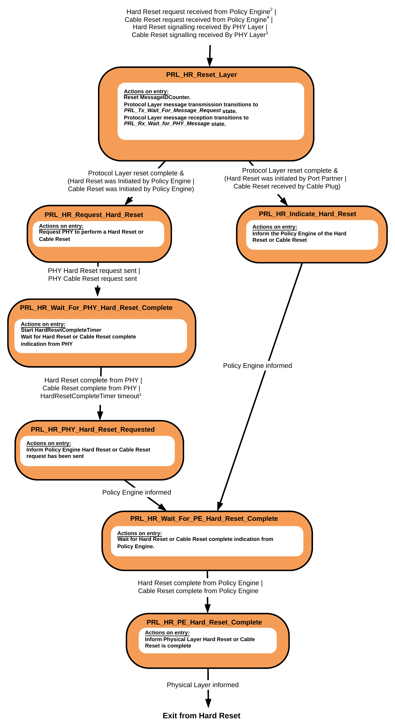
- If the HardResetCompleteTimer timeout occurs this means that the PHY is still waiting to send the Hard Reset due to a non-Idle channel. This condition will be cleared once the PE Hard Reset is completed.
- Cable Plugs do not generate Hard Reset Signaling but are required to monitor for Hard Reset Signaling between the Port Partners and respond by resetting.
- Cable Reset Signaling is only recognized by a Cable Plug.
- Cable Reset Signaling cannot be generated by Cable Plugs.
9.1.2.4.1. PRL_HR_Reset_Layer State
The PRL_HR_Reset_Layer State defines the Mode of operation of both the Protocol Layer transmission and reception State machines during a Hard Reset or Cable Reset. During Hard Reset no USB Power Delivery Protocol Messages are sent or received; only Hard Reset Signaling is present after which the communication channel is assumed to have been disabled by the PHY Layer until completion of the Hard Reset. During Cable Reset no USB Power Delivery Protocol Messages are sent to or received by the Cable Plug but other USB Power Delivery communication May continue.
The Protocol Layer Shall enter the PRL_HR_Reset_Layer State from any other State when:
- A Hard Reset Request is received from the Policy Engine or
- Hard Reset Signaling is received from the PHY Layer or
- A Cable Reset Request is received from the Policy Engine or
- Cable Reset Signaling is received from the PHY Layer.
On entry to the PRL_HR_Reset_Layer State the Protocol Layer Shall reset the MessageIDCounter. It Shall also reset the states of the Protocol Layer transmission and reception State machines to their starting points. The Protocol Layer transmission State machine Shall transition to the PRL_Tx_Wait_for_Message_Request State. The Protocol Layer reception State machine Shall transition to the PRL_Rx_Wait_for_PHY_Message State.
The Protocol Layer Shall transition to the PRL_HR_Request_Hard_Reset State when:
- The Protocol Layer's reset is complete and
- The Hard Reset Request has originated from the Policy Engine or
- The Cable Reset Request has originated from the Policy Engine.
The Protocol Layer Shall transition to the PRL_HR_Indicate_Hard_Reset State when:
- The Protocol Layer's reset is complete and
- The Hard Reset Request has been passed up from the PHY Layer or
- A Cable Reset Request has been passed up from the PHY Layer (Cable Plug only).
9.1.2.4.2. PRL_HR_Indicate_Hard_Reset State
On entry to the PRL_HR_Indicate_Hard_Reset State the Protocol Layer Shall indicate to the Policy Engine that either Hard Reset Signaling or Cable Reset Signaling has been received.
The Protocol Layer Shall transition to the PRL_HR_Wait_for_PE_Hard_Reset_Complete State when:
- The indication to the Policy Engine has been sent.
9.1.2.4.3. PRL_HR_Request_Hard_Reset State
On entry to the PRL_HR_Request_Hard_Reset State the Protocol Layer Shall Request the PHY Layer to send either Hard Reset Signaling or Cable Reset Signaling.
The Protocol Layer Shall transition to the PRL_HR_Wait_for_PHY_Hard_Reset_Complete State when:
- The PHY Layer Hard Reset Signaling Request has been sent or
- The PHY Layer Cable Reset Signaling Request has been sent.
9.1.2.4.4. PRL_HR_Wait_for_PHY_Hard_Reset_Complete State
In the PRL_HR_Wait_for_PHY_Hard_Reset_Complete State the Protocol Layer Shall start the HardResetCompleteTimer and wait for the PHY Layer to indicate that the Hard Reset or Cable Reset has been completed.
The Protocol Layer Shall transition to the PRL_HR_PHY_Hard_Reset_Requested State when:
- A Hard Reset complete indication is received from the PHY Layer or
- A Cable Reset complete indication is received from the PHY Layer or
- The HardResetCompleteTimer times out.
9.1.2.4.5. PRL_HR_PHY_Hard_Reset_Requested State
On entry to the PRL_HR_PHY_Hard_Reset_Requested State the Protocol Layer Shall inform the Policy Engine that the PHY Layer has been requested to perform a Hard Reset or Cable Reset.
The Protocol Layer Shall transition to the PRL_HR_Wait_for_PE_Hard_Reset_Complete State when:
- The Indication to the Policy Engine has been sent.
9.1.2.4.6. PRL_HR_Wait_for_PE_Hard_Reset_Complete State
In the PRL_HR_Wait_for_PE_Hard_Reset_Complete State the Protocol Layer Shall wait for the Policy Engine to indicate that the Hard Reset or Cable Reset has been completed.
The Protocol Layer Shall transition to the PRL_HR_PE_Hard_Reset_Complete State when:
- A Hard Reset complete indication is received from the Policy Engine or
- A Cable Reset complete indication is received from the Policy Engine.
9.1.2.4.7. PRL_HR_PE_Hard_Reset_Complete
On entry to the PRL_HR_PE_Hard_Reset_Complete State the Protocol Layer Shall inform the PHY Layer that the Hard Reset or Cable Reset is complete.
The Protocol Layer Shall exit from the Hard Reset and return to normal operation when:
- The PHY Layer has been informed that the Hard Reset is complete so that it will re-enable the communications channel. If Hard Reset Signaling is still pending due to a non-Idle channel this Shall be cleared and not sent or the PHY Layer has been informed that the Cable Reset is complete.
9.2. Policy Engine Layer State Diagrams
9.2.1. Introduction to State diagrams
The State diagrams in this section define the operation of the Power Delivery Policy Engine.
Note: These State diagrams are not intended to replace a well written and robust design.
Figure 9.12. Outline of States
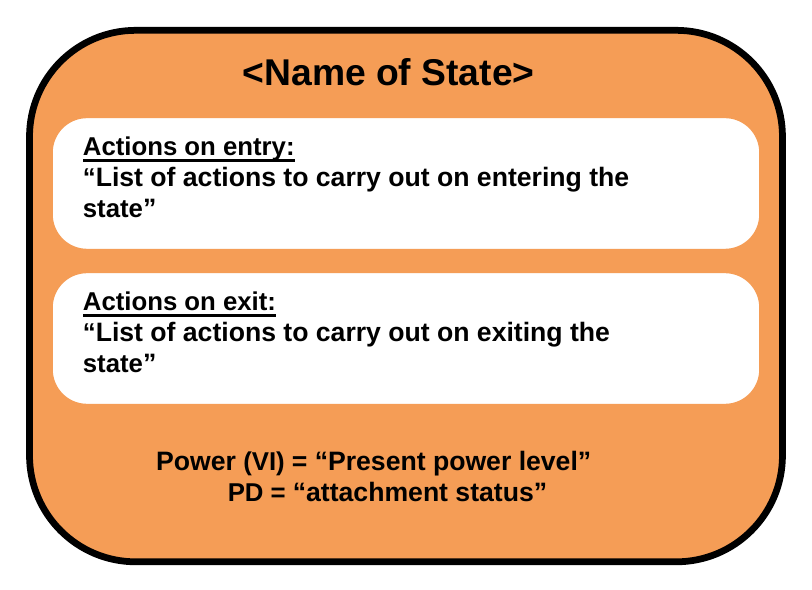
Figure 9.12 shows an outline of the states defined in the following sections. At the top there is the name of the State. This is followed by "Actions on entry" a list of actions carried out on entering the State. If there are also "Actions on exit" a list of actions carried out on exiting the State, then these are listed as well; otherwise, this box is omitted from the State. At the bottom the status of PD is listed:
- "Power" which indicates the present output power for a Source Port or input power for a Sink Port.
- "PD" which indicates the present Attachment status either "Attached", "Detached", or "unknown".
Transitions from one State to another are indicated by arrows with the conditions listed on the arrow. Where there are multiple conditions, these are Connected using either a logical OR "|" or a logical AND "&".
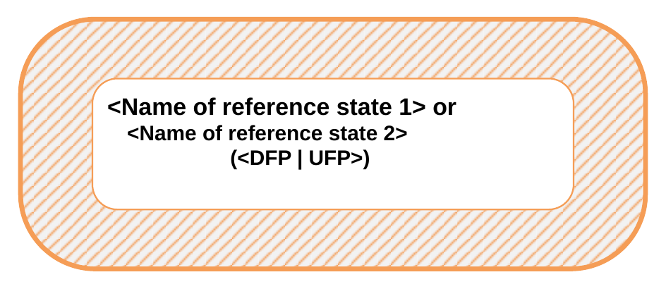
In some cases, there are transitions which can occur from any State to a particular State. These are indicated by an arrow which is unconnected to a State at one end, but with the other end (the point) Connected to the final State. In some State diagrams it is necessary to enter or exit from states in other diagrams (e.g., Source Port or Sink Port State diagrams). Figure 9.13 indicates how such references are made. The reference is indicated with a hatched box. The box contains the name of the State and whether the State is a DFP or UFP. It has also been necessary to indicate conditional entry to either Source Port or Sink Port State diagrams. This is achieved by the use of a bulleted list indicating the preconditions (see example in Figure 9.14 ). It is also possible that the entry and return states are the same. Figure 9.15 indicates a State reference where each referenced State corresponds to either the entry State or the exit State.
Figure 9.13. References to states
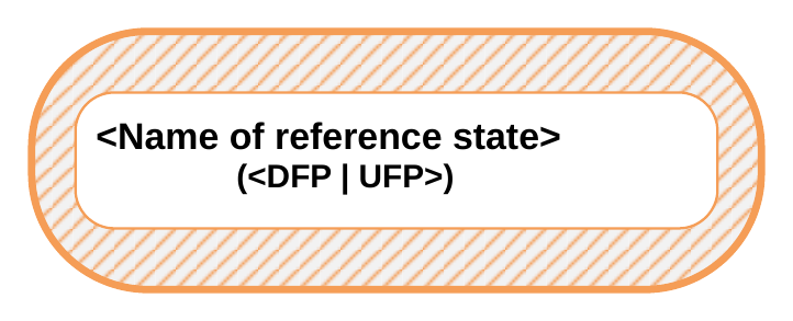
Figure 9.14. Example of State reference with conditions
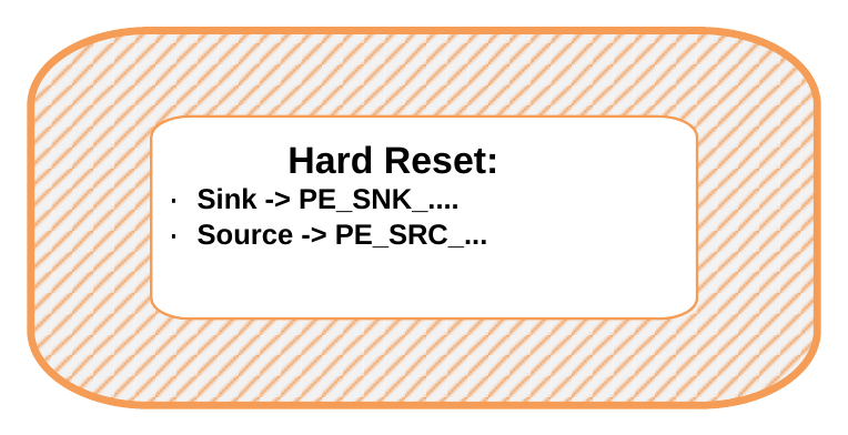
Figure 9.15. Example of State reference with the same entry and exit
Timers are included in many of the states. Timers are initialized (set to their starting condition) and run (timer is counting) in the particular State it is referenced. As soon as the State is exited then the timer is no longer active. Where the timers continue to run outside of the State (such as the NoResponseTimer), this is called out in the text. Timeouts of the timers are listed as conditions on State transitions.
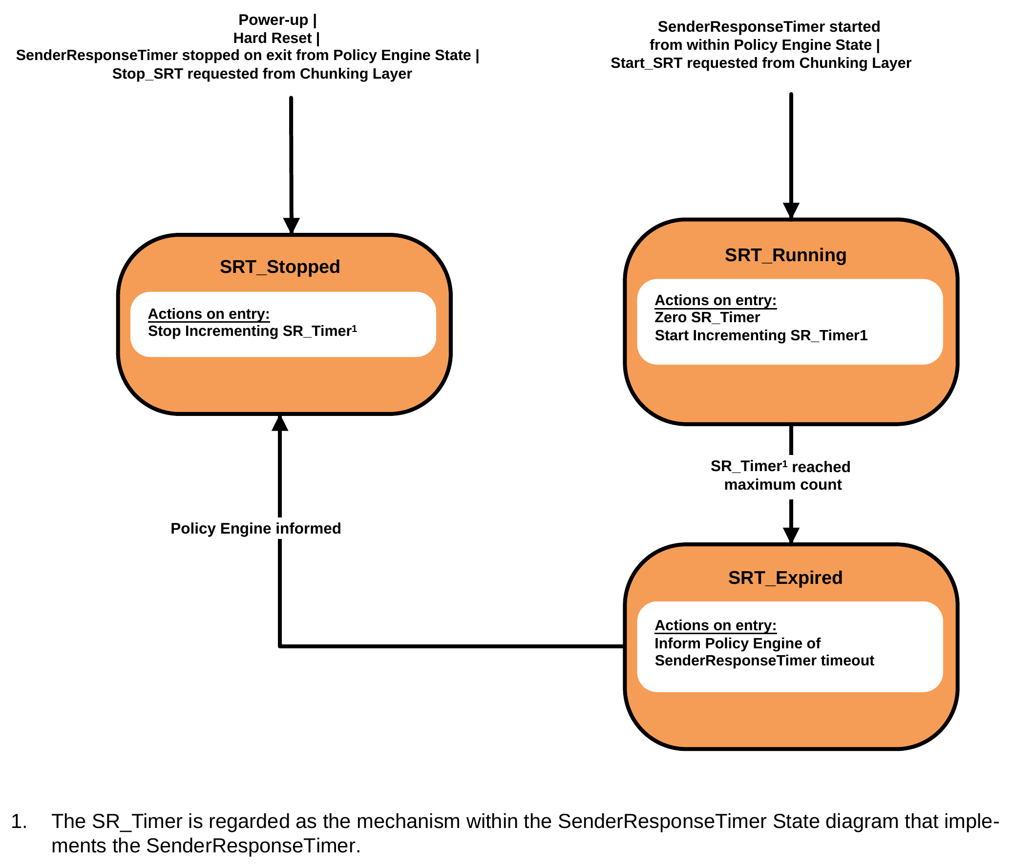
The SenderResponseTimer is a special case, as it May be stopped and started from outside the states in which it is used. To allow this to be done without over-complicating the State diagrams, the SenderResponseTimer is described with its own State diagram ( Figure 9.16 ). The control of this Timer is shared between the Policy Engine and the Chunking Layer.
Conditions listed on State transitions will come from one of three sources and, when there is a conflict, Should be serviced in the following order:
- Message and related indications passed up to the Policy Engine from the Protocol Layer (Message sent; Message received etc.).
- Events triggered within the Policy Engine e.g., timer timeouts.
- Information and requests coming from the Device Policy Manager relating either to Local Policy, or to other modules which the Device Policy Manager controls such as power supply and USB Type-C Port Control.
Note: The following State diagrams are not intended to cover all possible corner cases that could be encountered. For example, where an outgoing Message is Discarded, due to an incoming Message by the Protocol Layer it will be necessary for the higher layers of the system to handle a retry of the AMS that was being initiated, after first handling the incoming Message.
9.2.2. SenderResponseTimer State Diagram
This figure shows the State diagram for the Policy Engine in a Source Port or a Sink Port. The following sections describe operation in each of the states.
Figure 9.16. SenderResponseTimer Policy Engine State Diagram
- The
SR_Timeris regarded as the mechanism within theSenderResponseTimerState diagram that implements theSenderResponseTimer.
9.2.2.1. SRT_Stopped State
The SRT_Stopped State Shall be the starting State for the SenderResponseTimer either on power up or after a Hard Reset. On entry to this State the Policy Engine Shall stop incrementing the SR_Timer. The Policy Engine Shall transition to the SRT_Running State:
- When the
SenderResponseTimeris started from within a Policy Engine State, or - When a
Start_SRTis requested from the Chunking Layer.
9.2.2.2. SRT_Running State
On entry to the SRT_Running State the SenderResponseTimer State machine Shall:
- Set the
SR_Timerto zero - Start running
SR_Timer.
The SenderResponseTimer State machine Shall transition to the SRT_Expired State:
- When the
SR_Timerreaches its maximum count
The SenderResponseTimer State machine Shall transition to the SRT_Stopped State:
- When the
SenderResponseTimeris stopped by exiting a Policy Engine State, or - When a
Stop_SRTis requested from the Chunking Layer
9.2.2.3. SRT_Expired State
On entry to the SRT_Running State the SenderResponseTimer State machine Shall Inform Policy Engine of SenderResponseTimer timeout.
The Policy Engine Shall then transition to the SRT_Stopped State:
- When the Policy Engine has been informed.
9.2.3. Policy Engine Source Port State Diagram
This figure shows the State diagram for the Policy Engine in a Source Port. The following sections describe operation in each of the states.
Figure 9.17. Source Port State Diagram
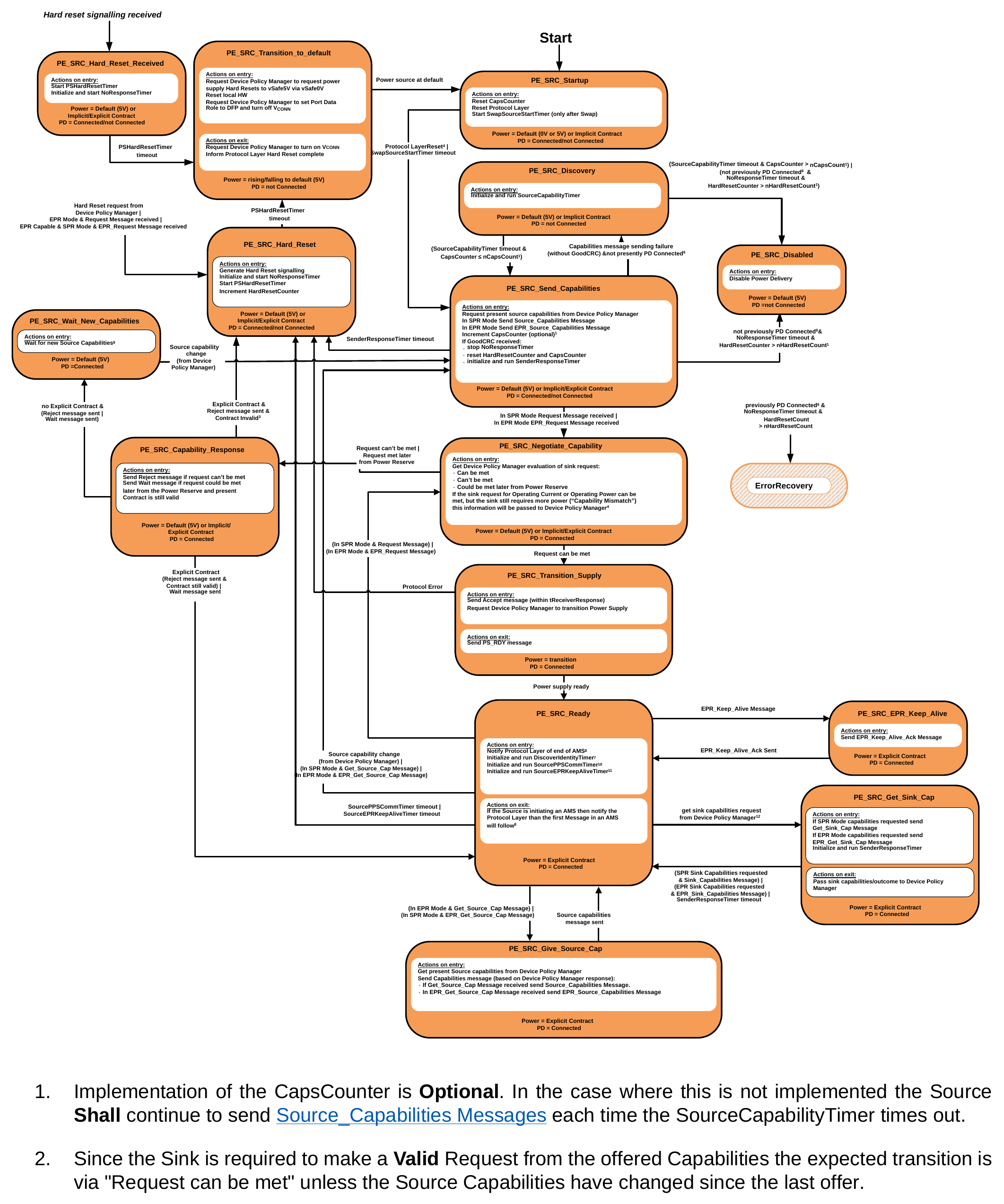
- Implementation of the
CapsCounteris Optional. In the case where this is not implemented the Source Shall continue to send Source_Capabilities Messages each time theSourceCapabilityTimertimes out. - Since the Sink is required to make a Valid Request from the offered Capabilities the expected transition is via "Request can be met" unless the Source Capabilities have changed since the last offer.
- "Contract Invalid" means that the previously Negotiated voltage and Current values are no longer included in the Source's new Capabilities. If the Sink fails to make a Valid Request in this case, then Power Delivery operation is no longer possible and Power Delivery Mode is exited with a Hard Reset.
- After a Power Swap the New Source is required to wait an additional
tSwapSourceStartbefore sending a Source_Capabilities Message. This delay is not required when first starting up a system. - PD Connected is defined as a situation when the Port Partners are actively communicating. The Port Partners remain PD Connected after a Swap until there is a transition to Disabled or the connector is able to identify a Detach
- Port Partners are no longer PD Connected after a Hard Reset, but consideration needs to be given as to whether there has been a PD Connection while the Ports have been Attached to prevent unnecessary USB Type-C Error Recovery.
- The
DiscoverIdentityTimeris run when this is a VCONN Source and a PD Connection with a Cable Plug needs to be established i.e. no GoodCRC Message has yet been received in response to a Discover Identity Command. - See Section 5.2.2, Section 7.31.13, and Section 7.2.
- In the
PE_SRC_Wait_New_CapabilitiesState the Device Policy Manager Should either decide to send no further Source Capabilities or Should send a different set of Source Capabilities. Continuing to send the same set of Source Capabilities could result in a live lock situation. - The
SourcePPSCommTimeris only initialized and run when the present Explicit Contract is for a PPS APDO. Sources that do not support PPS, do not need to implement theSourcePPSCommTimer. - The
SourceEPRKeepAliveTimeris only initialized and run when the Source is in EPR Mode; Sources that do not support EPR Mode do not need to implement theSourceEPRKeepAliveTimer. - Either SPR or EPR Sink Capabilities May be requested, regardless of whether or not the Source is currently operating in SPR or EPR Mode.
9.2.3.1. PE_SRC_Startup State
PE_SRC_Startup Shall be the starting State for a Source Policy Engine either on power up or after a Hard Reset. On entry to this State the Policy Engine Shall reset the CapsCounter and reset the Protocol Layer.
Note: Resetting the Protocol Layer will also reset the MessageIDCounter and stored MessageID.
The Policy Engine Shall transition to the PE_SRC_Send_Capabilities State:
- When the Protocol Layer reset has completed if the
PE_SRC_StartupState was entered due to the system first starting up. - When the
SwapSourceStartTimertimes out if thePE_SRC_StartupState was entered as the result of a Power Role Swap.
Note: Sources Shall remain in the PE_SRC_Startup State, without sending any Source_Capabilities Messages until a plug is Attached.
9.2.3.2. PE_SRC_Discovery State
On entry to the PE_SRC_Discovery State the Policy Engine Shall initialize and run the SourceCapabilityTimer in order to trigger sending a Source_Capabilities Message.
The Policy Engine Shall transition to the PE_SRC_Send_Capabilities State when:
- The
SourceCapabilityTimertimes out andCapsCounter≤nCapsCount. The Policy Engine May Optionally go to thePE_SRC_DisabledState when: - The Port Partners are not presently PD Connected
- And the
SourceCapabilityTimertimes out - And
CapsCounter>nCapsCount.
The Policy Engine Shall go to the PE_SRC_Disabled State when:
- The Port Partners have not been PD Connected (the Source Port remains Attached to a Port it has not had a PD Connection with during this Attachment)
- And the
NoResponseTimertimes out - And the
HardResetCounter>nHardResetCount.
Note: In the PE_SRC_Disabled State the Attached Device is assumed to be unresponsive. The Policy Engine operates as if the Device is Detached until such time as a Detach/Re-Attach is detected.
9.2.3.3. PE_SRC_Send_Capabilities State
Note: This State can be entered from the PE_SRC_Soft_Reset State.
On entry to the PE_SRC_Send_Capabilities State the Policy Engine Shall Request the present Port Capabilities from the Device Policy Manager. The Policy Engine Shall then Request the Protocol Layer to send a Capabilities Message containing these Capabilities. The Policy Engine Shall Request:
- A Source_Capabilities Message if the Source is in SPR Mode or
- An EPR_Source_Capabilities Message if the Source is in EPR Mode. The Policy Engine Shall then increment the
CapsCounter(if implemented). If a GoodCRC Message is received, then the Policy Engine Shall: - Stop the
NoResponseTimer. - Reset the
HardResetCounterandCapsCounterto zero.
Note: The HardResetCounter Shall only be set to zero in this State and at power up; its value Shall be maintained during a Hard Reset.
- Initialize and run the
SenderResponseTimer.
Once a Source_Capabilities Message has been received and acknowledged by a GoodCRC Message, the Sink is required to then send a Request Message within tSenderResponse.
The Policy Engine Shall transition to the PE_SRC_Negotiate_Capability State when:
- A Request Message is received from the Sink and the Source is operating in SPR Mode or
An EPR_Request Message is received from the Sink and the Source is operating in EPR Mode. The Policy Engine Shall transition to the PE_SRC_Discovery State when:
- The Protocol Layer indicates that the Message has not been sent and we are presently not Connected. This is part of the Capabilities sending process whereby successful Message sending indicates connection to a PD Sink Port.
The Policy Engine Shall transition to the PE_SRC_Hard_Reset State when:
- The
SenderResponseTimertimes out. In this case a transition back to USB Default Operation is required.
When the Port Partners have not been PD Connected (the Source Port remains Attached to a Port it has not had a PD Connection with during this Attachment), and the NoResponseTimer times out, and the HardResetCounter > nHardResetCount, the Policy Engine Shall do one of the following:
- Transition to the
PE_SRC_DiscoveryState. - Transition to the
PE_SRC_DisabledState.
Note: That in either case the Attached Device is assumed to be unresponsive. The Policy Engine Should operate as if the Device is Detached until such time as a Detach/Re-Attach is detected.
The Policy Engine Shall go to the ErrorRecovery State when:
- The Port Partners have previously been PD Connected (the Source Port remains Attached to a Port it has had a PD Connection with during this Attachment)
- And, the
NoResponseTimertimes out. - And, the
HardResetCounter>nHardResetCount.
9.2.3.4. PE_SRC_Negotiate_Capability State
On entry to the PE_SRC_Negotiate_Capability State the Policy Engine Shall ask the Device Policy Manager to evaluate the Request from the Attached Sink. The response from the Device Policy Manager Shall be one of the following:
- The Request can be met.
- The Request cannot be met
- The Request could be met later from the Power Reserve.
The Policy Engine Shall transition to the PE_SRC_Transition_Supply State when:
- The Request can be met.
The Policy Engine Shall transition to the PE_SRC_Capability_Response State when:
- The Request cannot be met.
- Or the Request can be met later from the Power Reserve.
9.2.3.5. PE_SRC_Transition_Supply State
The Policy Engine Shall be in the PE_SRC_Transition_Supply State while the power supply is transitioning from one power to another. On entry to the PE_SRC_Transition_Supply State, the Policy Engine Shall Request the Protocol Layer to send an Accept Message and inform the Device Policy Manager that it Shall transition the power supply to the Requested power level.
Note: If the power supply is currently operating at the requested power no change will be necessary.
On exit from the PE_SRC_Transition_Supply State the Policy Engine Shall Request the Protocol Layer to send a PS_RDY Message.
The Policy Engine Shall transition to the PE_SRC_Ready State when:
The Device Policy Manager informs the Policy Engine that the power supply is ready. The Policy Engine Shall transition to the PE_SRC_Hard_Reset State when:
- A Protocol Error occurs.
9.2.3.6. PE_SRC_Ready State
In the PE_SRC_Ready State the PD Source Shall be operating at a stable power with no ongoing Negotiation. It Shall respond to requests from the Sink, events from the Device Policy Manager. On entry to the PE_SRC_Ready State the Source Shallnotify the Protocol Layer of the end of the Atomic Message Sequence (AMS). If the transition into PE_SRC_Ready is the result of Protocol Error that has not caused a Soft Reset (see Section 9.2.5.1 ) then the notification to the Protocol Layer of the end of the AMS Shall Not be sent since there is a Message to be processed.
On entry to the PE_SRC_Ready State if this is a VCONN Source which needs to establish communication with a Cable Plug, the Policy Engine Shall:
- Initialize and run the
DiscoverIdentityTimer(no GoodCRC Message response yet received to Discover Identity Message).
On entry to the PE_SRC_Ready State if the current Explicit Contract is for a PPS APDO, then the Policy Engine
Shall do the following:
- Initialize and run the
SourcePPSCommTimer.
On entry to the PE_SRC_Ready State if the current Explicit Contract is for EPR Mode, then the Policy Engine Shall do the following:
- Initialize and run the
SourceEPRKeepAliveTimer.
On exit from the PE_SRC_Ready, if the Source is initiating an AMS, then the Policy Engine Shall notify the Protocol Layer that the first Message in an AMS will follow.
The Policy Engine Shall transition to the PE_SRC_Send_Capabilities State when:
- The Device Policy Manager indicates that Source Capabilities have changed or
- A Get_Source_Cap Message is received, and the Source is in SPR Mode or
An EPR_Get_Source_Cap Message is received, and the Source is in EPR Mode. The Policy Engine Shall transition to the PE_SRC_Negotiate_Capability State when:
- A Request Message is received, and the Source is in SPR Mode or
An EPR_Request Message is received, and the Source is in EPR Mode. The Policy Engine Shall transition to the PE_SRC_Get_Sink_Cap State when:
- The Device Policy Manager asks for the Sink Capabilities.
The Policy Engine Shall transition to the PE_SRC_Hard_Reset State when:
- The Source is operating as a PPS and the
SourcePPSCommTimerTimer times-out or
The Source is in EPR Mode and the SourceEPRKeepAliveTimer Timer times-out. The Policy Engine Shall transition to the PE_SRC_EPR_Keep_Alive State when:
- An EPR_Keep_Alive Message is received.
The Policy Engine Shall transition to the PE_SRC_Give_Source_Cap State when:
-
In EPR Mode and a Get_Source_Cap Message is received or
-
In SPR Mode and an EPR_Get_Source_Cap Message is received.
If a transition into the PE_SRC_Ready State will result in an immediate transition out of the PE_SRC_Ready State within tSrcHoldsBus e.g. it is due to a Protocol Error that has not resulted in a Soft Reset, then the notifications of the end of AMS and first Message in an AMS May Not be sent to avoid changing the Rp value unnecessarily.
9.2.3.7. PE_SRC_Disabled State
In the PE_SRC_Disabled State the PD Source supplies default power and is unresponsive to USB Power Delivery messaging, but not to Hard Reset Signaling.
9.2.3.8. PE_SRC_Capability_Response State
The Policy Engine Shall enter the PE_SRC_Capability_Response State if there is a Request received from the Sink that cannot be met based on the present Capabilities. When the present Explicit Contract is not within the present Capabilities it is regarded as Invalid and a Hard Reset will be triggered.
On entry to the PE_SRC_Hard_Reset State the Policy Engine Shall Request the Protocol Layer to send one of the following:
-
Reject Message - if the Request cannot be met or the present Explicit Contract is Invalid.
-
Wait Message - if the Request could be met later from the Power Reserve. A Wait Message Shall Not be sent if the present Explicit Contract is Invalid.
The Policy Engine Shall transition to the PE_SRC_Ready State when:
-
There is an Explicit Contract and
-
A Reject Message has been sent and the present Explicit Contract is still Valid or
-
A Wait Message has been sent.
The Policy Engine Shall transition to the PE_SRC_Hard_Reset State when:
-
There is an Explicit Contract and
-
The Reject Message has been sent and the present Explicit Contract is Invalid (i.e., the Sink had to Request a new value so instead we will return to USB Default Operation).
The Policy Engine Shall transition to the PE_SRC_Wait_New_Capabilities State when:
-
There is no Explicit Contract and
-
A Reject Message has been sent or
-
A Wait Message has been sent.
9.2.3.9. PE_SRC_Hard_Reset State
The Policy Engine Shall transition to the PE_SRC_Hard_Reset State from any State when:
-
Hard Reset Request from Device Policy Manager or
-
In EPR Mode and a Request Message is received or
- PR Capable and in SPR Mode and an EPR_Request Message is received.
On entry to the PE_SRC_Hard_Reset State the Policy Engine Shall:
-
Request the generation of Hard Reset Signaling by the PHY Layer which might take up to tHardResetComplete.
-
initialize and run the NoResponseTimer.
Note: The NoResponseTimer Shall continue to run in every State until it is stopped or times out.
The Policy Engine Shall transition to the PE_SRC_Transition_to_default State when:
- The PSHardResetTimer times out.
9.2.3.10. PE_SRC_Hard_Reset_Received State
The Policy Engine Shall transition from any State to the PE_SRC_Hard_Reset_Received State when:
- Hard Reset Signaling is detected.
On entry to the PE_SRC_Hard_Reset_Received State the Policy Engine Shall:
-
initialize and run the PSHardResetTimer
-
initialize and run the NoResponseTimer.
Note: The NoResponseTimer Shall continue to run in every State until it is stopped or times out. The Policy Engine Shall transition to the PE_SRC_Transition_to_default State when:
- The PSHardResetTimer times out.
9.2.3.11. PE_SRC_Transition_to_default State
On entry to the PE_SRC_Transition_to_default State the Policy Engine Shall:
-
Indicate to the Device Policy Manager that the power supply Shall Hard Reset (see Section 4.4).
-
Request a reset of the local hardware Request the Device Policy Manager to set the Port Data Role to DFP and turn off VCONN. On exit from the PE_SRC_Transition_to_default State the Policy Engine Shall:
-
Request the Device Policy Manager to turn on VCONN inform the Protocol Layer that the Hard Reset is complete. The Policy Engine Shall transition to the PE_SRC_Startup State when:
-
The Device Policy Manager indicates that the power supply has reached the default level.
9.2.3.12. PE_SRC_Get_Sink_Cap State
In this State the Policy Engine, due to a Request from the Device Policy Manager, Shall Request the Capabilities from the Attached Sink. On entry to the PE_SRC_Get_Sink_Cap State the Policy Engine Shall Request the Protocol Layer to send a Get_Sink_Cap Message in order to retrieve the Sink Capabilities. The Policy Engine Shall send:
- A Get_Sink_Cap Message when the Device Policy Manager requests SPR Capabilities or
An EPR_Get_Sink_Cap Message when the Device Policy Manager requests EPR Capabilities. The Policy Engine Shall then start the SenderResponseTimer. On exit from the PE_SRC_Get_Sink_Cap State the Policy Engine Shall inform the Device Policy Manager of the outcome (Capabilities or response timeout).
The Policy Engine Shall transition to the PE_SRC_Ready State when:
-
SPR Sink Capabilities were requested and a Sink_Capabilities Message is received or
-
EPR Sink Capabilities were requested and an EPR_Sink_Capabilities Message is received or
-
The SenderResponseTimer times out.
9.2.3.13. PE_SRC_Wait_New_Capabilities State
In this State the Policy Engine has been unable to Negotiate an Explicit Contract and is waiting for new Capabilities from the Device Policy Manager.
The Policy Engine Shall transition to the PE_SRC_Send_Capabilities State when:
- The Device Policy Manager indicates that Source Capabilities have changed.
9.2.3.14. PE_SRC_EPR_Keep_Alive State
On entry to the PE_SRC_EPR_Keep_Alive State the Policy Engine Shall send a EPR_Keep_Alive_Ack Message. The Policy Engine Shall transition to the PE_SRC_Ready State when:
- The EPR_Keep_Alive_Ack Message has been sent.
9.2.3.15. PE_SRC_Give_Source_Cap State
On entry to the PE_SRC_Give_Source_Cap State the Policy Engine Shall Request the Device Policy Manager for the current system Capabilities.
The Policy Engine Shall then Request the Protocol Layer to send a Source Capabilities Message containing these Capabilities.
The Policy Engine Shall send:
- A Source_Capabilities Message when a Get_Source_Cap Message is received or
An EPR_Source_Capabilities Message when a EPR_Get_Source_Cap Message is received. The Policy Engine Shall transition to the PE_SNK_Ready State when:
- The Source Capabilities Message has been successfully sent.
9.2.4. Policy Engine Sink Port State Diagram
This figure shows the State diagram for the Policy Engine in a Sink Port. The following sections describe operation in each of the states.
Figure 9.18. Sink Port State Diagram
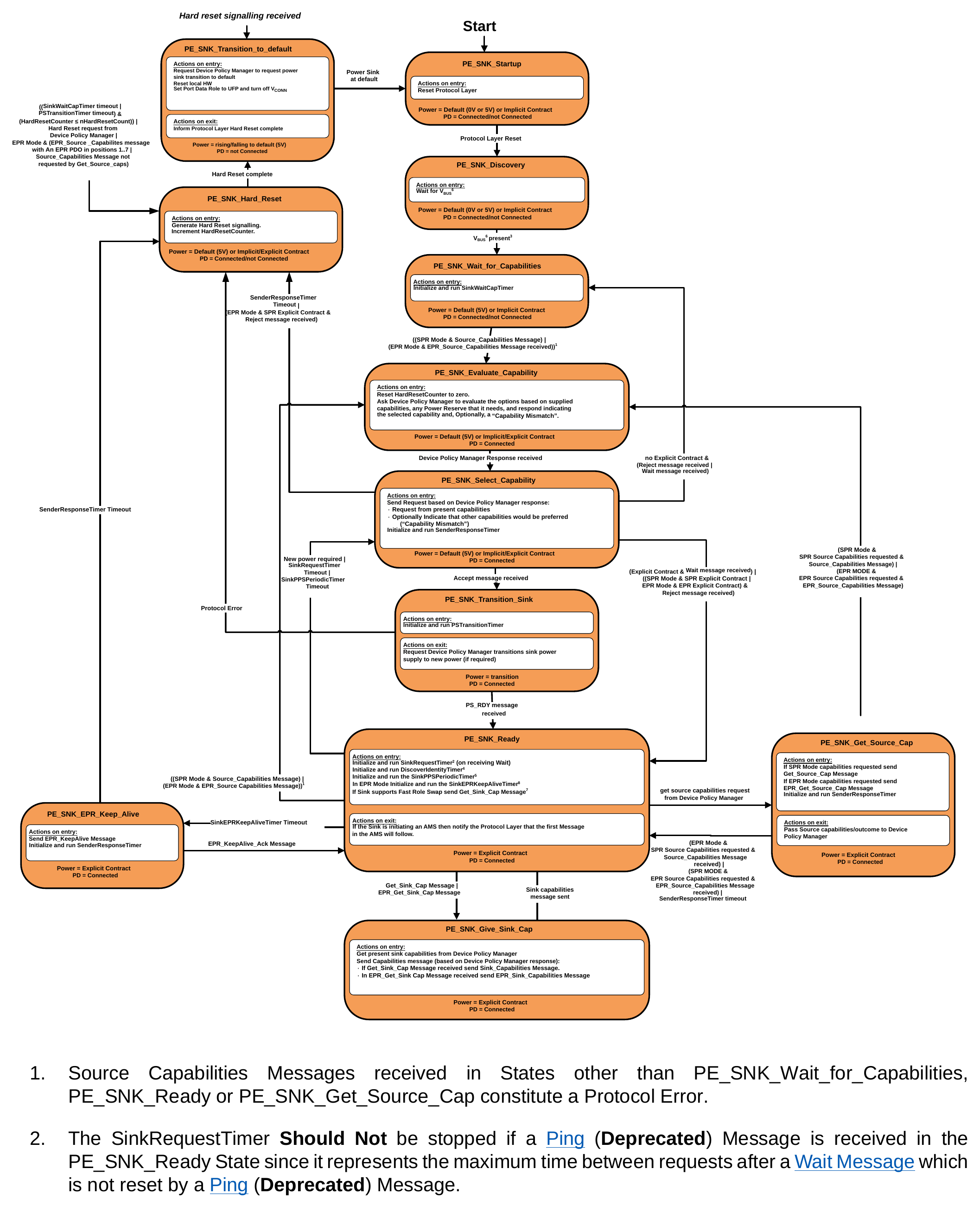
- Source Capabilities Messages received in States other than PE_SNK_Wait_for_Capabilities, PE_SNK_Ready or PE_SNK_Get_Source_Cap constitute a Protocol Error.
- The SinkRequestTimer Should Not be stopped if a Ping (Deprecated) Message is received in the PE_SNK_Ready State since it represents the maximum time between requests after a Wait Message which is not reset by a Ping (Deprecated) Message.
- During a Hard Reset the Source voltage will transition to
vSafe0Vand then transition tovSafe5V. Sinks need to ensure that VBUS present is not indicated until after the Source has completed the Hard Reset process by detecting both of these transitions. - The DiscoverIdentityTimer is run when this is a VCONN Source and a PD Connection with a Cable Plug needs to be established i.e., no GoodCRC Message has yet been received in response to a Discover Identity Command.
- The SinkPPSPeriodicTimer is only initialized and run when the present Explicit Contract is for a PPS APDO. Sinks that do not support PPS do not need to implement the SinkPPSPeriodicTimer.
- A Sink that is a VPD May use VCONN as a proxy for VBUS.
- To be sent once, and only required if Fast Role Swap is supported by the Sink.
9.2.4.1. PE_SNK_Startup State
PE_SNK_Startup Shall be the starting State for a Sink Policy Engine either on power up or after a Hard Reset. On entry to this State the Policy Engine Shall reset the Protocol Layer.
Note: Resetting the Protocol Layer will also reset the MessageIDCounter and stored MessageID (see Section 9.1.2.3). Once the reset process completes, the Policy Engine Shall transition to the PE_SNK_Discovery State.
9.2.4.2. PE_SNK_Discovery State
In the PE_SNK_Discovery State the Sink Policy Engine waits for VBUS to be present. The Policy Engine Shall transition to the PE_SNK_Wait_for_Capabilities State when:
- The Device Policy Manager indicates that VBUS has been detected.
9.2.4.3. PE_SNK_Wait_for_Capabilities State
On entry to the PE_SNK_Wait_for_Capabilities State the Policy Engine Shall initialize and start the SinkWaitCapTimer.
The Policy Engine Shall transition to the PE_SNK_Evaluate_Capability State when:
-
The Sink is in SPR Mode and a Source_Capabilities Message is received or
-
The Sink is in EPR Mode and an EPR_Source_Capabilities Message is received.
9.2.4.4. PE_SNK_Evaluate_Capability State
The PE_SNK_Evaluate_Capability State is first entered when the Sink receives its first Source_Capabilities Message from the Source. At this point the Sink knows that it is Attached to and communicating with a PD Capable Source.
On entry to the PE_SNK_Evaluate_Capability State the Policy Engine Shall Request the Device Policy Manager to evaluate the supplied Source Capabilities based on Local Policy. The Device Policy Manager Shall indicate to the Policy Engine the new power level required, selected from the present offered Capabilities. The Device Policy Manager Shall also indicate to the Policy Engine a Capabilities Mismatch if the offered power does not meet the Device's requirements.
The Policy Engine Shall transition to the PE_SNK_Select_Capability State when:
- A response is received from the Device Policy Manager.
9.2.4.5. PE_SNK_Select_Capability State
On entry to the PE_SNK_Select_Capability State the Policy Engine Shall Request the Protocol Layer to send a response Message, based on the evaluation from the Device Policy Manager. The Message Shall be one of the following:
-
A Request from the offered Source Capabilities.
-
A Request from the offered Source Capabilities with an indication that another power level would be preferred (Capability Mismatch bit set).
When in SPR Mode a Request Message Shall be sent.
When in EPR Mode an EPR_Request Message Shall be sent.
The Policy Engine Shall initialize and run the SenderResponseTimer.
The Policy Engine Shall transition to the PE_SNK_Transition_Sink State when:
- An Accept Message is received from the Source.
The Policy Engine Shall transition to the PE_SNK_Wait_for_Capabilities State when:
-
There is no Explicit Contract in place and
-
A Reject Message is received from the Source or
-
A Wait Message is received from the Source.
The Policy Engine Shall transition to the PE_SNK_Ready State when:
-
There is an SPR Explicit Contract in SPR Mode or an EPR Explicit Contract in EPR Mode and a Reject Message is received from the Source or
-
There is an Explicit Contract in place and a Wait Message is received from the Source.
The Policy Engine Shall transition to the PE_SNK_Hard_Reset State when:
-
A SenderResponseTimer timeout occurs or
-
An EPR Explicit Contract has not been established in EPR Mode and a Reject Message is received from the Source.
9.2.4.6. PE_SNK_Transition_Sink State
On entry to the PE_SNK_Transition_Sink State the Policy Engine Shall initialize and run the PSTransitionTimer (timeout will lead to a Hard Reset see Section 9.2.4.8 and Shall then Request the Device Policy Manager to transition the Sink's power supply to the new power level.
Note: If there is no power level change the Device Policy Manager Should Not affect any change to the power supply.
On exit from the PE_SNK_Transition_Sink State the Policy Engine Shall Request the Device Policy Manager to transition the Sink's power supply to the new power level.
The Policy Engine Shall transition to the PE_SNK_Ready State when:
- A PS_RDY Message is received from the Source.
The Policy Engine Shall transition to the PE_SNK_Hard_Reset State when:
- A Protocol Error occurs.
9.2.4.7. PE_SNK_Ready State
-
The Device Policy Manager requests an update of the remote Source Capabilities. The Policy Engine Shall transition to the PE_SNK_EPR_Keep_Alive State when:
-
The SinkEPRKeepAliveTimer timeouts out.
9.2.4.8. PE_SNK_Hard_Reset State
The Policy Engine Shall transition to the PE_SNK_Hard_Reset State from any State when:
-
(PSTransitionTimer times out) and
-
(HardResetCounter ≤ nHardResetCount))
-
Hard Reset Request from Device Policy Manager or
-
In EPR Mode and
• An EPR_Source_Capabilities Message is received with an EPR PDO or APDO in object positions 1…7 or
• A Source_Capabilities Message is received that has not been requested using a Get_Source_Cap Message.
-
The Policy Engine May transition to the PE_SNK_Hard_Reset State from any State when:
-
SinkWaitCapTimer times out.
Note: If the SinkWaitCapTimer times out and the HardResetCounter is greater than nHardResetCount the Sink Shall assume that the Source is non-responsive.
Note: The HardResetCounter is reset on a power cycle or Detach.
On entry to the PE_SNK_Hard_Reset State the Policy Engine Shall Request the generation of Hard Reset Signaling by the PHY Layer and increment the HardResetCounter.
The Policy Engine Shall transition to the PE_SNK_Transition_to_default State when:
- The Hard Reset is complete.
9.2.4.9. PE_SNK_Transition_to_default State
The Policy Engine Shall transition from any State to PE_SNK_Transition_to_default State when:
- Hard Reset Signaling is detected.
When Hard Reset Signaling is received or transmitted then the Policy Engine Shall transition from any State to PE_SNK_Transition_to_default. This State can also be entered from the PE_SNK_Hard_Reset State. On entry to the PE_SNK_Transition_to_default State the Policy Engine Shall:
-
Indicate to the Device Policy Manager that the Sink Shall transition to default
-
Request a reset of the local hardware
- Request the Device Policy Manager that the Port Data Role is set to UFP.
The Policy Engine Shall transition to the PE_SNK_Startup State when:
- The Device Policy Manager indicates that the Sink has reached the default level.
9.2.4.10. PE_SNK_Give_Sink_Cap State
On entry to the PE_SNK_Give_Sink_Cap State the Policy Engine Shall Request the Device Policy Manager for the current system Capabilities. The Policy Engine Shall then Request the Protocol Layer to send a Sink_Capabilities Message containing these Capabilities. The Policy Engine Shall send:
-
A Sink_Capabilities Message when a Get_Sink_Cap Message is received or
-
An EPR_Sink_Capabilities Message when a EPR_Get_Sink_Cap Message is received. The Policy Engine Shall transition to the PE_SNK_Ready State when:
-
The Sink_Capabilities Message has been successfully sent.
9.2.4.11. PE_SNK_EPR_Keep_Alive
- On entry to the PE_SNK_EPR_Keep_Alive State the Policy Engine Shall send an EPR_Keep_Alive Message and initialize and run the SenderResponseTimer.
The Policy Engine Shall transition to the PE_SNK_Ready State when:
- A EPR_Keep_Alive_Ack Message is received.
The Policy Engine Shall transition to the PE_SNK_Hard_Reset State when:
- The SenderResponseTimer times out.
9.2.4.12. PE_SNK_Get_Source_Cap State
-
On entry to the PE_SNK_Get_Source_Cap State the Policy Engine Shall Request the Protocol Layer to send a get Source Capabilities Message in order to retrieve the Source Capabilities. The Policy Engine Shall send:
-
A Get_Source_Cap Message when the Device Policy Manager requests SPR Capabilities or
-
An EPR_Get_Source_Cap Message when the Device Policy Manager requests EPR Capabilities. The Policy Engine Shall then start the SenderResponseTimer.
On exit from the PE_SNK_Get_Source_Cap State the Policy Engine Shall inform the Device Policy Manager of the outcome (Capabilities or response timeout).
The Policy Engine Shall transition to the PE_SNK_Ready State when:
-
In EPR Mode and SPR Source Capabilities were requested and a Source_Capabilities Message is received or
-
In SPR Mode and EPR Source Capabilities were requested and an EPR_Source_Capabilities Message is received or
-
The SenderResponseTimer times out.
The Policy Engine Shall transition to the PE_SNK_Evaluate_Capability State when:
- In SPR Mode and SPR Source Capabilities were requested and a Source_Capabilities Message is received or
- In EPR Mode and EPR Source Capabilities were requested and an EPR_Source_Capabilities Message is received.
9.2.5. SOP Soft Reset and Protocol Error State Diagrams
9.2.5.1. SOP Source Port Soft Reset and Protocol Error State Diagram
This figure shows the State diagram for the Policy Engine in a Source Port when performing a Soft Reset of its Port Partner i.e., using SOP. The following sections describe operation in each of the states.
Figure 9.19. SOP Source Port Soft Reset and Protocol Error State Diagram
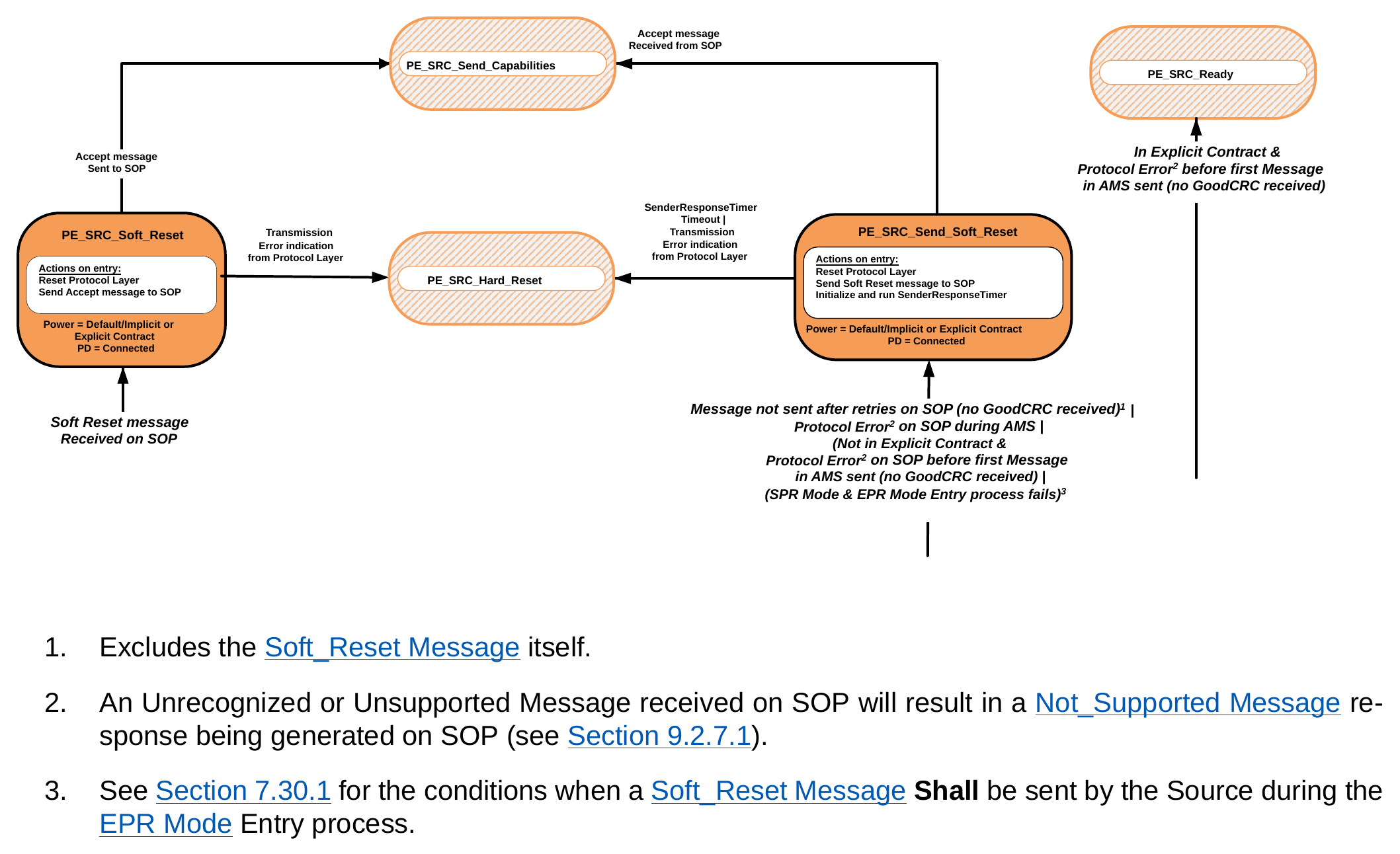
- Excludes the Soft_Reset Message itself.
- An Unrecognized or Unsupported Message received on SOP will result in a Not_Supported Message response being generated on SOP (see Section 9.2.7.1).
- See Section 7.30.1 for the conditions when a Soft_Reset Message Shall be sent by the Source during the EPR Mode Entry process.
9.2.5.1.1. PE_SRC_Send_Soft_Reset State
The PE_SRC_Send_Soft_Reset State Shall be entered from any State when:
-
A Protocol Error on SOP is detected by the Protocol Layer during an AMS (see Section 7.1.1) or
-
A Message has not been sent after retries to the Sink or
-
When not in an Explicit Contract and Protocol Errors occurred on SOP during any AMS where the first Message in the AMS has not yet been sent i.e., an Unexpected Message is received instead of the expected GoodCRC Message response or
-
When in SPR Mode and the EPR Mode Entry process fails. The main exceptions to this rule are when:
• The Source is in the PE_SRC_Send_Capabilities State, there is a Source_Capabilities Message sending failure on SOP (without a GoodCRC Message) and the Source is not presently Attached (as indicated in Figure 9.17 ). In this case, the PE_SRC_Discovery State is entered (see Section 9.2.3.2 ).
-
When the voltage is in transition due to a new Explicit Contract being Negotiated (see Section 9.2.3 ). In this case Hard Reset Signaling will be generated.
-
During a Power Role Swap when the power supply is in transition (see Section 9.2.20.3 and Section 9.2.20.4 ). In this case USB Type-C Error Recovery will be triggered directly.
-
During a Data Role Swap when there is a mismatch in the Port Data Role field (see Table 6.9 ). In this case USB Type-C Error Recovery will be triggered directly.
Protocol Errors occurring in the following situations Shall Not lead to a Soft Reset, but Shall result in a transition to the PE_SRC_Ready State where the Message received will be handled as if it had been received in the PE_SRC_Ready State:
- When in an Explicit Contract and Protocol Errors occurred on SOP during any AMS where the first Message in the AMS has not yet been sent i.e., an Unexpected Message is received instead of the expected GoodCRC Message response.
On entry to the PE_SRC_Send_Soft_Reset State the Policy Engine Shall Request the SOP Protocol Layer to perform a Soft Reset, then Shall send a Soft_Reset Message to the Sink on SOP, and initialize and run the SenderResponseTimer.
The Policy Engine Shall transition to the PE_SRC_Send_Capabilities State when:
- An Accept Message has been received on SOP.
The Policy Engine Shall transition to the PE_SRC_Hard_Reset State when:
-
A SenderResponseTimer timeout occurs.
-
Or the Protocol Layer indicates that a transmission error has occurred.
9.2.5.1.2. PE_SRC_Soft_Reset State
- The PE_SRC_Soft_Reset State Shall be entered from any State when a Soft_Reset Message is received on SOP from the Protocol Layer.
On entry to the PE_SRC_Soft_Reset State the Policy Engine Shall reset the SOP Protocol Layer and Shall then Request the Protocol Layer to send an Accept Message on SOP.
The Policy Engine Shall transition to the PE_SRC_Send_Capabilities State (see Section 9.2.3.3 ) when:
- The Accept Message has been sent on SOP.
The Policy Engine Shall transition to the PE_SRC_Hard_Reset State when:
- The Protocol Layer indicates that a transmission error has occurred.
9.2.5.2. SOP Sink Port Soft Reset and Protocol Error State Diagram
This figure shows the State diagram for the Policy Engine in a Sink Port when performing a Soft Reset of its Port Partner i.e., using SOP. The following sections describe operation in each of the states.
Figure 9.20. Sink Port Soft Reset and Protocol Error Diagram
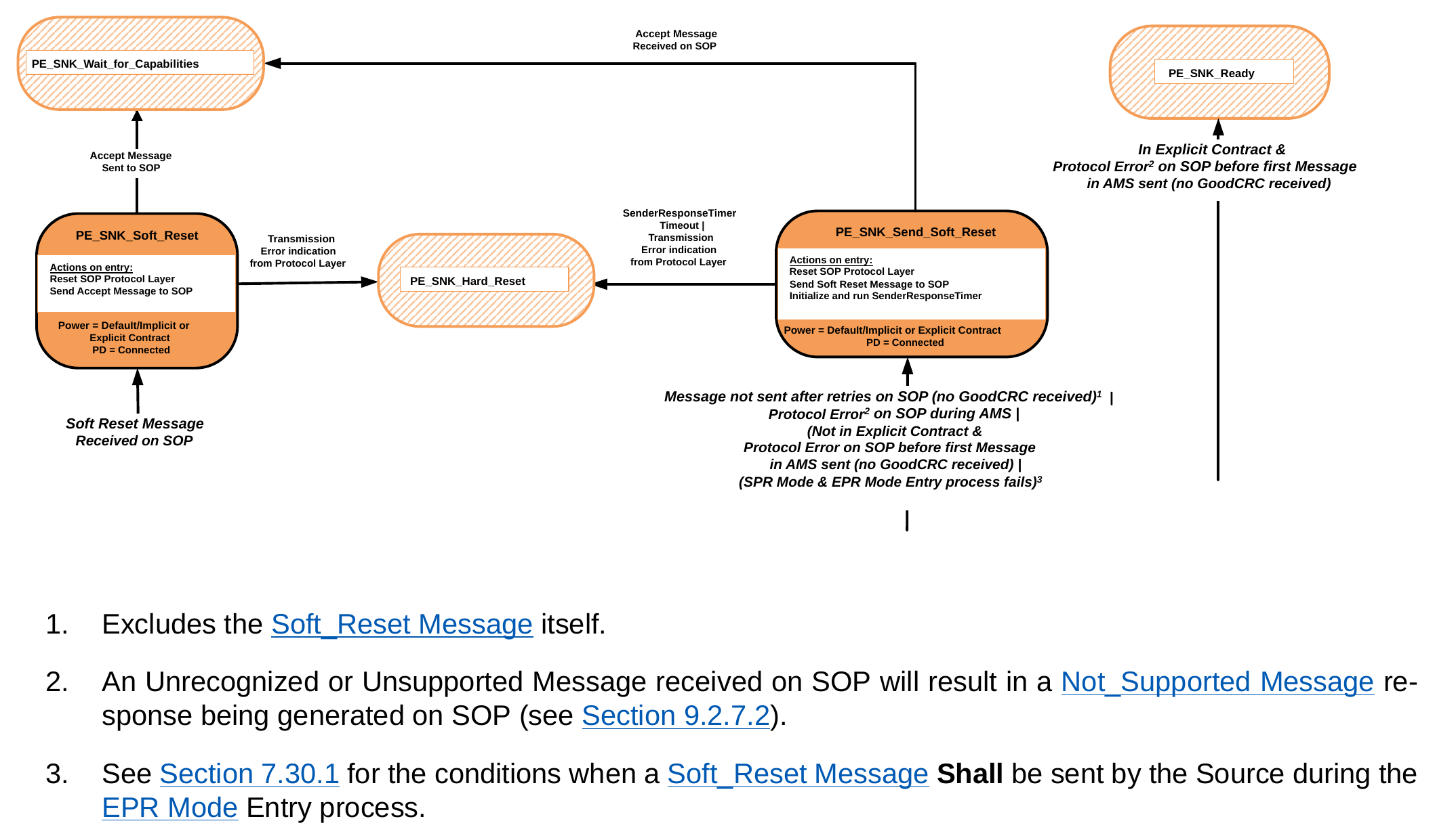
- Excludes the Soft_Reset Message itself.
- An Unrecognized or Unsupported Message received on SOP will result in a Not_Supported Message response being generated on SOP (see Section 9.2.7.2).
- See Section 7.30.1 for the conditions when a Soft_Reset Message Shall be sent by the Source during the EPR Mode Entry process.
9.2.5.2.1. PE_SNK_Send_Soft_Reset State
The PE_SNK_Send_Soft_Reset State Shall be entered from any State when:
-
A Protocol Error on SOP is detected by the Protocol Layer during an AMS (see Section 7.1.1) or
-
A Message has not been sent after retries to the Sink or
-
When not in an Explicit Contract and Protocol Errors occurred on SOP during any AMS where the first Message in the AMS has not yet been sent i.e., an Unexpected Message is received instead of the expected GoodCRC Message response.
-
When in SPR Mode and the EPR Mode Entry process fails. The main exceptions to this rule are when:
• When the voltage is in transition due to a new Explicit Contract being Negotiated (see Section 9.2.4 ). In this case a Hard Reset will be generated.
• During a Power Role Swap when the power supply is in transition (see Section 9.2.20.3 and Section 9.2.20.4 ). In this case a Hard Reset will be triggered directly.
• During a Data Role Swap when the DFP/UFP Data Roles are changing. In this case USB Type-C Error Recovery will be triggered directly.
Note: Protocol Errors occurring in the following situations Shall Not lead to a Soft Reset, but Shall result in a transition to the PE_SNK_Ready State where the Message received will be handled as if it had been received in the PE_SNK_Ready State:
- When in an Explicit Contract and Protocol Errors occurred on SOP during any AMS where the first Message in the AMS has not yet been sent i.e., an Unexpected Message is received instead of the expected GoodCRC Message response.
On entry to the PE_SNK_Send_Soft_Reset State the Policy Engine Shall Request the SOP Protocol Layer to perform a Soft Reset, then Shall send a Soft_Reset Message on SOP to the Source, and initialize and run the SenderResponseTimer.
The Policy Engine Shall transition to the PE_SNK_Wait_for_Capabilities State when:
- An Accept Message has been received on SOP.
The Policy Engine Shall transition to the PE_SNK_Hard_Reset State when:
-
A SenderResponseTimer timeout occurs.
-
Or the Protocol Layer indicates that a transmission error has occurred.
9.2.5.2.2. PE_SNK_Soft_Reset State
- The PE_SNK_Soft_Reset State Shall be entered from any State when a Soft_Reset Message is received on SOP from the Protocol Layer.
On entry to the PE_SNK_Soft_Reset State the Policy Engine Shall reset the SOP Protocol Layer and Shall then Request the Protocol Layer to send an Accept Message on SOP. The Policy Engine Shall transition to the PE_SNK_Wait_for_Capabilities State when:
- The Accept Message has been sent on SOP.
The Policy Engine Shall transition to the PE_SNK_Hard_Reset State when:
- The Protocol Layer indicates that a transmission error has occurred.
9.2.6. Data Reset State Diagrams
9.2.6.1. DFP Data_Reset Message State Diagrams
Figure 9.21 shows the State diagram for a Data_Reset Message sent or received by a DFP.
Figure 9.21. DFP Data_Reset Message State Diagram
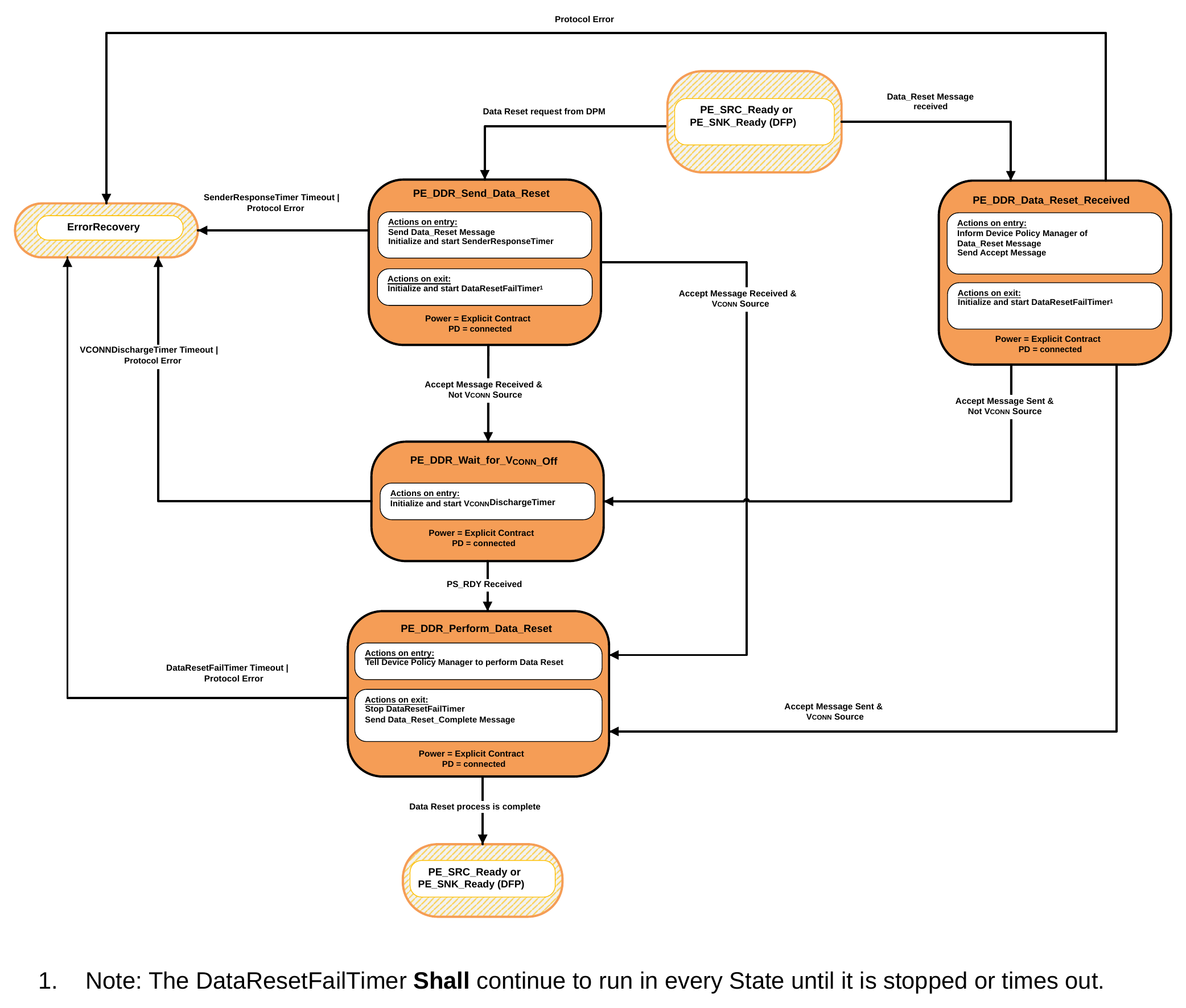
- Note: The DataResetFailTimer Shall continue to run in every State until it is stopped or times out.
9.2.6.1.1. PE_DDR_Send_Data_Reset State
The PE_DDR_Send_Data_Reset State Shall be entered from the PE_SRC_Ready or PE_SNK_Ready State when requested by the Device Policy Manager.
On entry to the PE_DDR_Send_Data_Reset State the Policy Engine Shall Request the Protocol Layer to send a Data_Reset Message and then initialize and start the SenderResponseTimer.
On exit from the PE_DDR_Send_Data_Reset State the Policy Engine Shall initialize and start the DataResetFailTimer.
The Policy Engine Shall transition to the PE_DDR_Perform_Data_Reset State when:
-
An Accept Message has been received and
-
The DFP is presently the VCONN Source.
The Policy Engine Shall transition to the PE_DDR_Wait_For_VCONN_Off State when:
-
An Accept Message has been received and
-
The DFP is not presently the VCONN Source.
The Policy Engine Shall transition to ErrorRecovery when:
-
A SenderResponseTimer timeout occurs or
-
A Protocol Error occurs.
9.2.6.1.2. PE_DDR_Data_Reset_Received State
The PE_DDR_Data_Reset_Received State Shall be entered from the PE_SRC_Ready or PE_SNK_Ready State when a Data_Reset Message is received.
On entry to the PE_DDR_Data_Reset_Received State the Policy Engine Shall inform the Device Policy Manager and then Shall send an Accept Message. On exit from the PE_DDR_Data_Reset_Received State, the Policy Engine Shall initialize and start the DataResetFailTimer.
The Policy Engine Shall transition to the PE_DDR_Perform_Data_Reset State when:
-
An Accept Message has been sent and
-
The DFP is presently the VCONN Source.
The Policy Engine Shall transition to the PE_DDR_Wait_For_VCONN_Off State when:
-
An Accept Message has been sent and
-
The DFP is not presently the VCONN Source.
The Policy Engine Shall transition to ErrorRecovery when:
- A Protocol Error occurs.
9.2.6.1.3. PE_DDR_Wait_For_VCONN_Off State
On entry to the PE_DDR_Wait_For_VCONN_Off State the Policy Engine Shall initialize and start the VCONNDischargeTimer.
The Policy Engine Shall transition to the PE_DDR_Perform_Data_Reset State when:
- A PS_RDY Message is received.
The Policy Engine Shall transition to ErrorRecovery when:
-
The VCONNDischargeTimer has timed out or
-
A Protocol Error occurs.
9.2.6.1.4. PE_DDR_Perform_Data_Reset State
On entry to the PE_DDR_Perform_Data_Reset State the Policy Engine Shall Request the Device Policy Manager to complete the Data Reset process as defined in Section 7.1.2. On exit from the PE_DDR_Perform_Data_Reset State the Policy Engine Shall stop the DataResetFailTimer and send a Data_Reset_Complete Message.
The Policy Engine Shall transition back to either the PE_SRC_Ready or PE_SNK_Ready State depending on the DFP's Power Role when:
- The DPM indicates that Data Reset process is complete (see Section 7.1.2). The Policy Engine Shall transition to ErrorRecovery when:
-
The DataResetFailTimer times out
-
A Protocol Error occurs.
9.2.6.2. UFP Data_Reset Message State Diagrams
Figure 9.22 shows the State diagram for a Data_Reset Message sent or received by a UFP.
Figure 9.22. UFP Data_Reset Message State Diagram
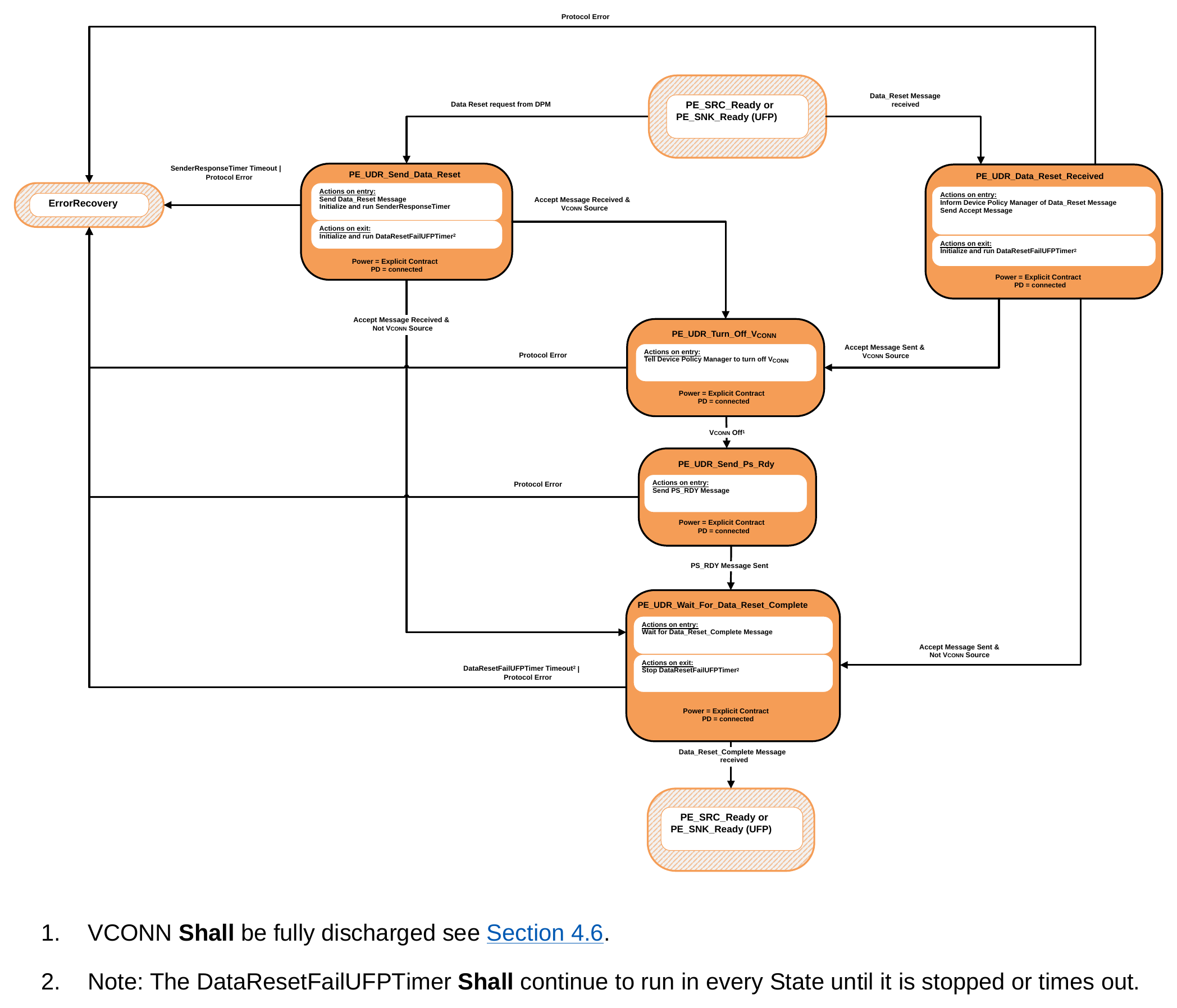
- VCONN Shall be fully discharged see Section 4.6.
- Note: The DataResetFailUFPTimer Shall continue to run in every State until it is stopped or times out.
9.2.6.2.1. PE_UDR_Send_Data_Reset State
The PE_UDR_Send_Data_Reset State Shall be entered from the PE_SRC_Ready or PE_SNK_Ready State when requested by the Device Policy Manager.
On entry to the PE_UDR_Send_Data_Reset State the Policy Engine Shall Request the Protocol Layer to send a Data_Reset Message and then initialize and run the SenderResponseTimer. On exit from the PE_UDR_Send_Data_Reset State the Policy Engine Shall initialize and run the DataResetFailUFPTimer.
The Policy Engine Shall transition to the PE_UDR_Turn_Off_VCONN State when:
-
An Accept Message has been received and
-
The UFP is presently the VCONN Source.
The Policy Engine Shall transition to the PE_UDR_Wait_For_Data_Reset_Complete State when:
-
An Accept Message has been received and
-
The UFP is not presently the VCONN Source.
The Policy Engine Shall transition to ErrorRecovery when:
-
The SenderResponseTimer has timed out or
-
A Protocol Error occurs.
9.2.6.2.2. PE_UDR_Data_Reset_Received State
The PE_UDR_Data_Reset_Received State Shall be entered from either the PE_SRC_Ready or PE_SNK_Ready State when a Data_Reset Message is received.
On entry to the PE_UDR_Data_Reset_Received State the Policy Engine Shall inform the Device Policy Manager and then Shall send an Accept Message. On exit from the PE_UDR_Data_Reset_Received State the Policy Engine Shall initialize and run the DataResetFailUFPTimer.
The Policy Engine Shall transition to the PE_UDR_Turn_Off_VCONN State when:
-
An Accept Message has been sent and
-
The UFP is presently the VCONN Source.
The Policy Engine Shall transition to the PE_UDR_Wait_For_Data_Reset_Complete State when:
-
An Accept Message has been sent and
-
The UFP is not presently the VCONN Source.
The Policy Engine Shall transition to ErrorRecovery when:
- A Protocol Error occurs.
9.2.6.2.3. PE_UDR_Turn_Off_VCONN State
On entry to the PE_UDR_Turn_Off_VCONN State the Policy Engine Shall Request the Device Policy Manager to turn off VCONN.
The Policy Engine Shall transition to the PE_UDR_Send_Ps_Rdy State when:
-
The DPM indicates that VCONN has been turned off (VCONN below vRaReconnect see [USB-C]). The Policy Engine Shall transition to ErrorRecovery when:
• A Protocol Error occurs.
9.2.6.2.4. PE_UDR_Send_Ps_Rdy State
- On entry to the PE_UDR_Send_Ps_Rdy State the Policy Engine Shall send a PS_RDY Message. The Policy Engine Shall transition to the PE_UDR_Wait_For_Data_Reset_Complete State when:
- The PS_RDY Message has been sent.
The Policy Engine Shall transition to ErrorRecovery when:
- A Protocol Error occurs.
9.2.6.2.5. PE_UDR_Wait_For_Data_Reset_Complete State
- On entry to the PE_UDR_Wait_For_Data_Reset_Complete State the Policy Engine Shall wait for the Data_Reset_Complete Message.
On exit from the PE_UDR_Wait_For_Data_Reset_Complete State the Policy Engine Shall stop the DataResetFailUFPTimer.
The Policy Engine Shall transition back to either the PE_SRC_Ready or PE_SNK_Ready State depending on the UFP's Power Role when:
- The Data_Reset_Complete Message is received. The Policy Engine Shall transition to ErrorRecovery when:
- The DataResetFailUFPTimer times out or
- A Protocol Error occurs.
9.2.7. Not Supported Message State Diagrams
9.2.7.1. Source Port Not Supported Message State Diagram
Figure 9.23 shows the State diagram for a Not_Supported Message sent or received by a Source Port.
Figure 9.23. Source Port Not Supported Message State Diagram
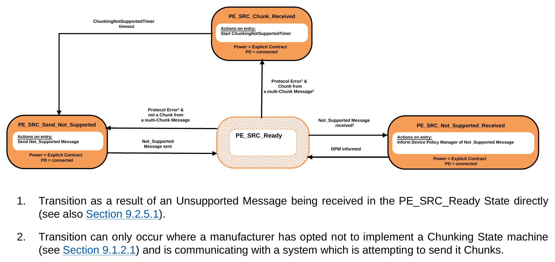
- Transition as a result of an Unsupported Message being received in the PE_SRC_Ready State directly (see also Section 9.2.5.1).
- Transition can only occur where a manufacturer has opted not to implement a Chunking State machine (see Section 9.1.2.1) and is communicating with a system which is attempting to send it Chunks.
9.2.7.1.1. PE_SRC_Send_Not_Supported State
The PE_SRC_Send_Not_Supported State Shall be entered from the PE_SRC_Ready State either as the result of a Protocol Error received during an interruptible AMS or as a result of an Unsupported Message being received in
the PE_SRC_Ready State directly except for the first Chunk in a multi-Chunk Message (see also Section 9.1.2.1 and Section 9.2.5.1 ).
On entry to the PE_SRC_Send_Not_Supported State (from the PE_SRC_Ready State) the Policy Engine Shall Request the Protocol Layer to send a Not_Supported Message.
The Policy Engine Shall transition back to the previous State (PE_SRC_Ready see Figure 9.17 ) when:
- The Not_Supported Message has been successfully sent.
9.2.7.1.2. PE_SRC_Not_Supported_Received State
The PE_SRC_Not_Supported_Received State Shall be entered from the PE_SRC_Ready State when a Not_Supported Message is received.
On entry to the PE_SRC_Not_Supported_Received State the Policy Engine Shall inform the Device Policy Manager.
The Policy Engine Shall transition back to the previous State (PE_SRC_Ready see Figure 9.17 ) when:
- The Device Policy Manager has been informed.
9.2.7.1.3. PE_SRC_Chunk_Received State
The PE_SRC_Chunk_Received State Shall be entered from the PE_SRC_Ready State as a result of an Unsupported Message being received in the PE_SRC_Ready State directly where the Message is a Chunk in a multi-Chunk Message (see also Section 9.1.2.1 and Section 9.2.5.1 ).
On entry to the PE_SRC_Chunk_Received State (from the PE_SRC_Ready State) the Policy Engine Shall initialize and run the ChunkingNotSupportedTimer.
The Policy Engine Shall transition to PE_SRC_Send_Not_Supported when:
- The ChunkingNotSupportedTimer has timed out.
9.2.7.2. Sink Port Not Supported Message State Diagram
Figure 9.24 shows the State diagram for a Not_Supported Message sent or received by a Sink Port.
Figure 9.24. Sink Port Not Supported Message State Diagram
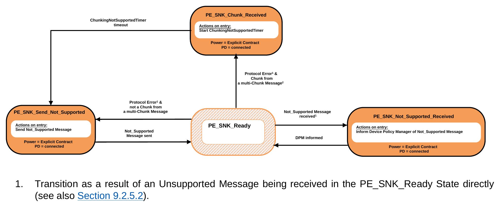
- Transition as a result of an Unsupported Message being received in the PE_SNK_Ready State directly (see also Section 9.2.5.2).
- Transition can only occur where a manufacturer has opted not to implement a Chunking State machine (see Section 9.1.2.1) and is communicating with a system which is attempting to send it Chunks.
9.2.7.2.1. PE_SNK_Send_Not_Supported State
The PE_SNK_Send_Not_Supported State Shall be entered from the PE_SNK_Ready State either as the result of a Protocol Error received during an interruptible AMS or as a result of an Unsupported Message being received in the PE_SNK_Ready State directly except for the first Chunk in a multi-Chunk Message (see also Section 9.1.2.1 and Section 9.2.5.1 ).
On entry to the PE_SNK_Send_Not_Supported State (from the PE_SNK_Ready State) the Policy Engine Shall Request the Protocol Layer to send a Not_Supported Message.
The Policy Engine Shall transition back to the previous State (PE_SNK_Ready see Figure 9.18 ) when:
- The Not_Supported Message has been successfully sent.
9.2.7.2.2. PE_SNK_Not_Supported_Received State
The PE_SNK_Not_Supported_Received State Shall be entered from the PE_SNK_Ready State when a Not_Supported Message is received.
On entry to the PE_SNK_Not_Supported_Received State the Policy Engine Shall inform the Device Policy Manager.
The Policy Engine Shall transition back to the previous State (PE_SNK_Ready see Figure 9.18 ) when:
- The Device Policy Manager has been informed.
9.2.7.2.3. PE_SNK_Chunk_Received State
The PE_SNK_Chunk_Received State Shall be entered from the PE_SNK_Ready State as a result of an Unsupported Message being received in the PE_SNK_Ready State directly where the Message is a Chunk in a multi-Chunk Message (see also Section 9.1.2.1 and Section 9.2.5.1 ).
On entry to the PE_SNK_Chunk_Received State (from the PE_SNK_Ready State) the Policy Engine Shall initialize and run the ChunkingNotSupportedTimer.
The Policy Engine Shall transition to PE_SNK_Send_Not_Supported when:
- The ChunkingNotSupportedTimer has timed out.
9.2.8. Alert State Diagrams
9.2.8.1. Source Port Source Alert State Diagram
Figure 9.25 shows the State diagram for an Alert Message sent by a Source Port.
Figure 9.25. Source Port Source Alert State Diagram
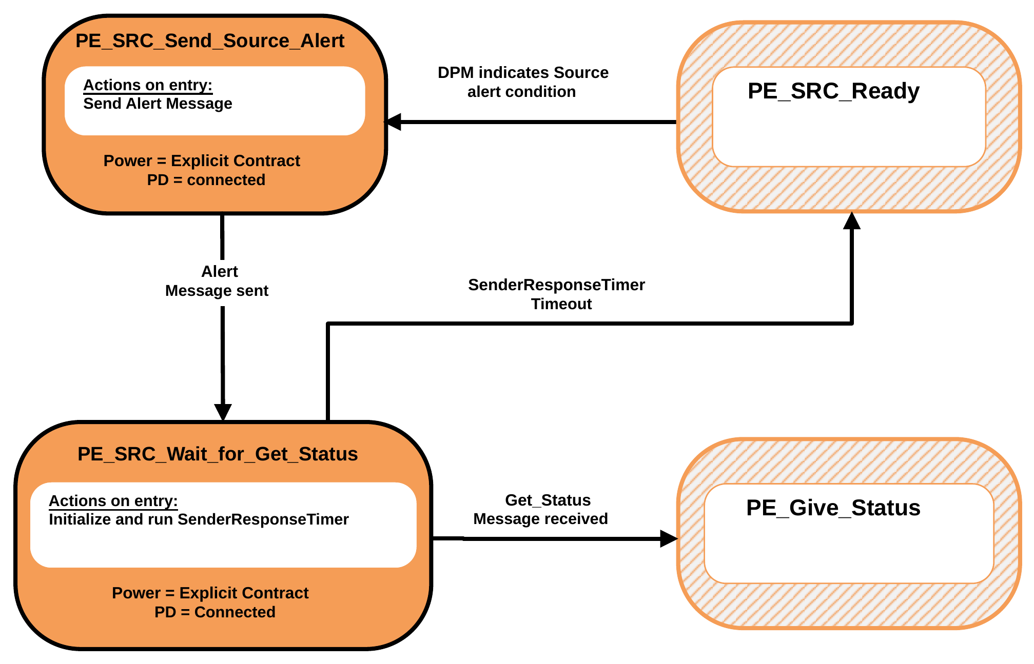
9.2.8.1.1. PE_SRC_Send_Source_Alert State
The PE_SRC_Send_Source_Alert State Shall be entered from the PE_SRC_Ready State when the Device Policy Manager indicates that there is a Source alert condition to be reported.
On entry to the PE_SRC_Send_Source_Alert State the Policy Engine Shall Request the Protocol Layer to send an Alert Message.
The Policy Engine Shall transition to the PE_SRC_Wait_for_Get_Status State when:
- The Alert Message has been successfully sent.
9.2.8.1.2. PE_SRC_Wait_for_Get_Status State
On entry to the PE_SRC_Wait_for_Get_Status State the Policy Engine Shall initialize and run the SenderResponseTimer.
The Policy Engine Shall transition back to the PE_Give_Status State (see Figure 9.36 ) when:
- A Get_Status Message is received.
The Policy Engine Shall transition back to PE_SRC_Ready (see Figure 9.17 ) when:
- The SenderResponseTimer times out.
9.2.8.2. Sink Port Source Alert State Diagram
Figure 9.26 shows the State diagram for an Alert Message received by a Sink Port.
Figure 9.26. Sink Port Source Alert State Diagram
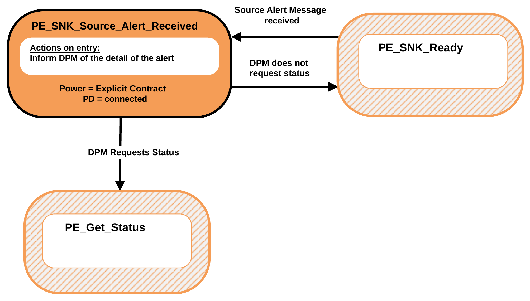
9.2.8.2.1. PE_SNK_Source_Alert_Received State
The PE_SNK_Source_Alert_Received State Shall be entered from the PE_SNK_Ready State when an Alert Message is received.
On entry to the PE_SNK_Source_Alert_Received State the Policy Engine Shall inform the Device Policy Manager of the details of the Source alert.
The Policy Engine Shall transition to the PE_Get_Status State (see Figure 9.35 ) when:
- The DPM requests status.
The Policy Engine Shall transition back to the PE_SNK_Ready State (see Figure 9.18 ) when:
- The DPM does not Request status.
9.2.8.3. Sink Port Sink Alert State Diagram
Figure 9.27 shows the State diagram for an Alert Message sent by a Sink Port.
Figure 9.27. Sink Port Sink Alert State Diagram
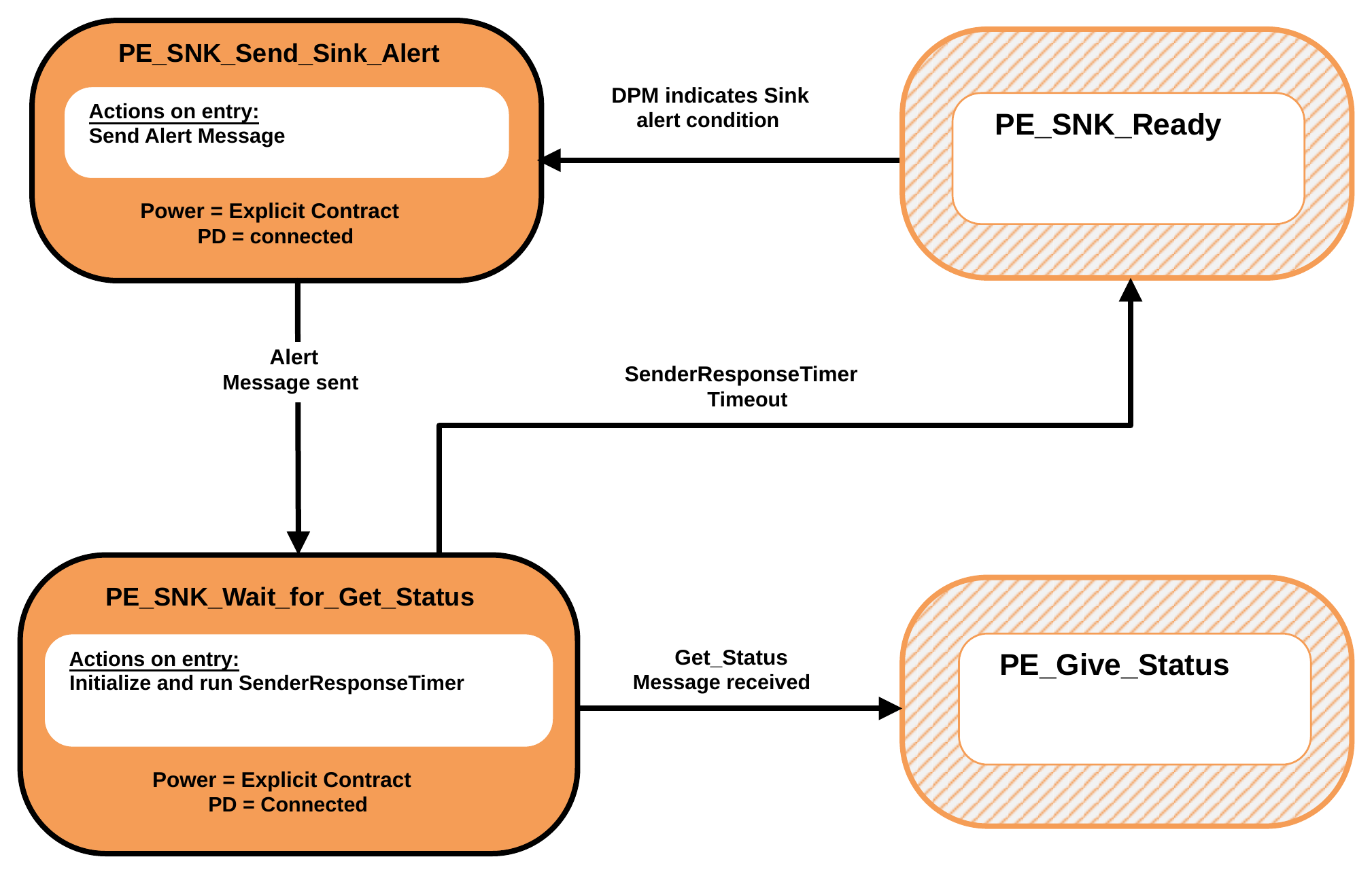
9.2.8.3.1. PE_SNK_Send_Sink_Alert State
The PE_SNK_Send_Sink_Alert State Shall be entered from the PE_SNK_Ready State when the Device Policy Manager indicates that there is a Source alert condition to be reported.
On entry to the PE_SNK_Send_Sink_Alert State the Policy Engine Shall Request the Protocol Layer to send an Alert Message.
The Policy Engine Shall transition to the PE_SNK_Wait_for_Get_Status State when:
- The Alert Message has been successfully sent.
9.2.8.3.2. PE_SNK_Wait_for_Get_Status State
On entry to the PE_SNK_Wait_for_Get_Status State the Policy Engine Shall initialize and run the SenderResponseTimer.
The Policy Engine Shall transition back to the PE_Give_Status State (see Figure 9.36 ) when:
- A Get_Status Message is received.
The Policy Engine Shall transition back to the PE_SNK_Ready (see Figure 9.18 ) when:
- The SenderResponseTimer times out.
9.2.8.4. Source Port Sink Alert State Diagram
Figure 9.28 shows the State diagram for an Alert Message received by a Source Port.
Figure 9.28. Source Port Sink Alert State Diagram
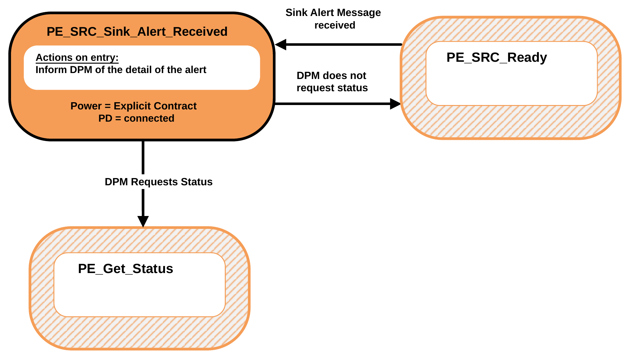
9.2.8.4.1. PE_SRC_Sink_Alert_Received State
The PE_SRC_Sink_Alert_Received State Shall be entered from the PE_SRC_Ready State when an Alert Message is received.
On entry to the PE_SRC_Sink_Alert_Received State the Policy Engine Shall inform the Device Policy Manager of the details of the Source alert.
The Policy Engine Shall transition to the PE_Get_Status State (see Figure 9.35 ) when:
- The DPM requests status.
The Policy Engine Shall transition back to the PE_SRC_Ready (see Figure 9.17 ) when:
- The DPM does not Request status.
9.2.9. Source/Sink Capabilities Extended State Diagrams
9.2.9.1. Sink Port Get Source Capabilities Extended State Diagram
Figure 9.29 shows the State diagram for a Sink on receiving a Request from the Device Policy Manager to get the Port Partner's extended Source Capabilities. See also Section 7.19.2.
Figure 9.29. Sink Port Get Source Capabilities Extended State Diagram
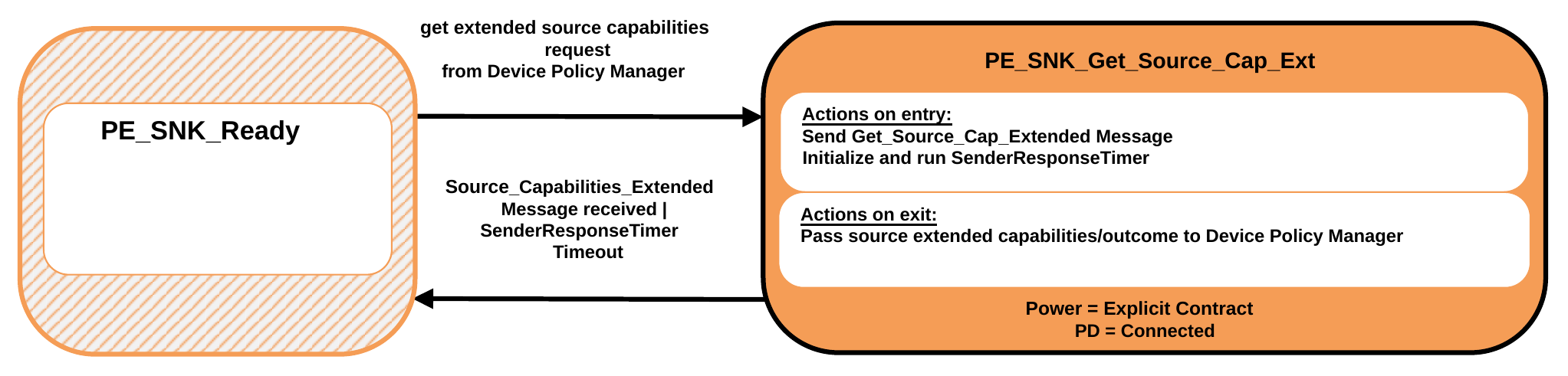
9.2.9.1.1. PE_SNK_Get_Source_Cap_Ext State
The Policy Engine Shall transition to the PE_SNK_Get_Source_Cap_Ext State, from the PE_SNK_Ready State, due to a Request to get the remote extended Source Capabilities from the Device Policy Manager.
On entry to the PE_SNK_Get_Source_Cap_Ext State the Policy Engine Shall send a Get_Source_Cap_Extended Message and initialize and run the SenderResponseTimer.
On exit from the PE_SNK_Get_Source_Cap_Ext State the Policy Engine Shall inform the Device Policy Manager of the outcome (Capabilities or response timeout).
The Policy Engine Shall transition back to the PE_SNK_Ready State (see Figure 9.18 ) when:
- A Source_Capabilities_Extended Message is received
- Or SenderResponseTimer times out.
9.2.9.2. Source Give Source Capabilities Extended State Diagram
Figure 9.30 shows the State diagram for a Source on receiving a Get_Source_Cap_Extended Message. See also Section 7.19.2.
Figure 9.30. Source Give Source Capabilities Extended State Diagram
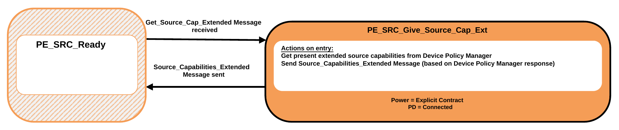
9.2.9.2.1. PE_SRC_Give_Source_Cap_Ext State
The Policy Engine Shall transition to the PE_SRC_Give_Source_Cap_Ext State, from the PE_SRC_Ready State, when a Get_Source_Cap_Extended Message is received.
On entry to the PE_SRC_Give_Source_Cap_Ext State the Policy Engine Shall Request the present extended Source Capabilities from the Device Policy Manager and then send a Source_Capabilities_Extended Message based on these Capabilities.
The Policy Engine Shall transition back to the PE_SRC_Ready State (see Figure 9.17 ) when:
- The Source_Capabilities_Extended Message has been successfully sent.
9.2.9.3. Source Port Get Sink Capabilities Extended State Diagram
Figure 9.31 shows the State diagram for a Source on receiving a Request from the Device Policy Manager to get the Port Partner's extended Sink Capabilities. See also Section 6.5.16.
Figure 9.31. Source Port Get Sink Capabilities Extended State Diagram
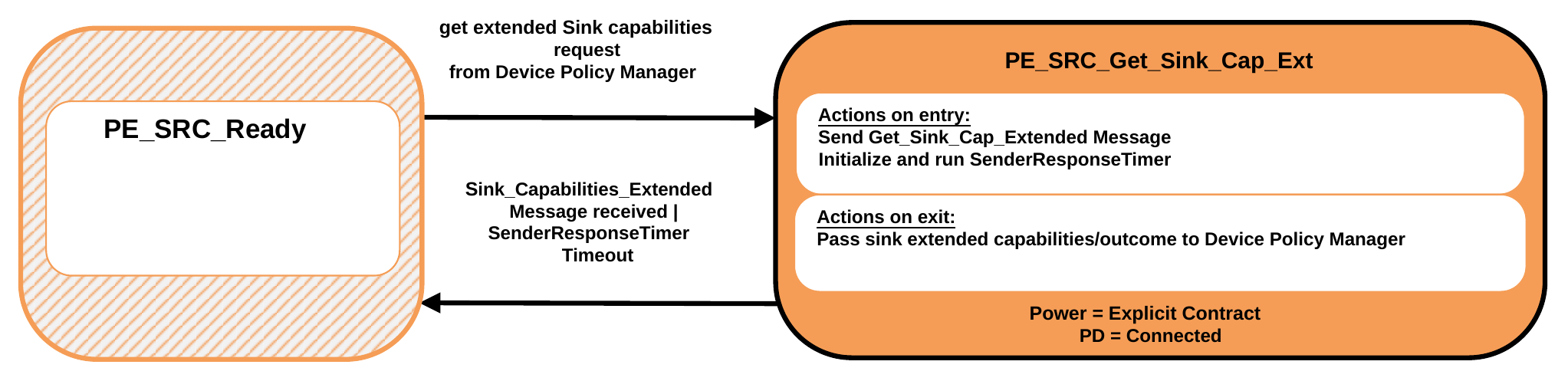
9.2.9.3.1. PE_SRC_Get_Sink_Cap_Ext State
The Policy Engine Shall transition to the PE_SRC_Get_Sink_Cap_Ext State, from the PE_SRC_Ready State, due to a Request to get the remote extended Source Capabilities from the Device Policy Manager.
On entry to the PE_SRC_Get_Sink_Cap_Ext State the Policy Engine Shall send a Get_Sink_Cap_Extended Message and initialize and run the SenderResponseTimer.
On exit from the PE_SRC_Get_Sink_Cap_Ext State the Policy Engine Shall inform the Device Policy Manager of the outcome (Capabilities or response timeout).
The Policy Engine Shall transition back to the PE_SRC_Ready State (see Figure 9.17 ) when:
- A Sink_Capabilities_Extended Message is received
- Or SenderResponseTimer times out.
9.2.9.4. Sink Give Sink Capabilities Extended State Diagram
Figure 9.32 shows the State diagram for a Source on receiving a Get_Sink_Cap_Extended Message. See also Section 6.5.16.
Figure 9.32. Sink Give Sink Capabilities Extended State Diagram
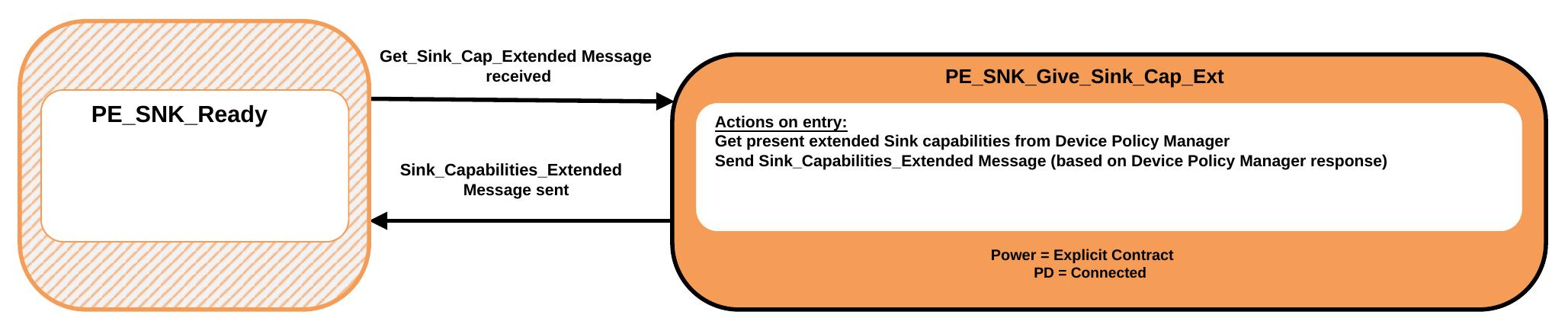
9.2.9.4.1. PE_SNK_Give_Sink_Cap_Ext State
The Policy Engine Shall transition to the PE_SNK_Give_Sink_Cap_Ext State, from the PE_SNK_Ready State, when a Get_Sink_Cap_Extended Message is received.
On entry to the PE_SNK_Give_Sink_Cap_Ext State the Policy Engine Shall Request the present extended Source Capabilities from the Device Policy Manager and then send a Sink_Capabilities_Extended Message based on these Capabilities.
The Policy Engine Shall transition back to the PE_SNK_Ready State (see Figure 9.18 ) when:
- The Sink_Capabilities_Extended Message has been successfully sent.
9.2.10. Source Information State Diagrams
9.2.10.1. Sink Port Get Source Information State Diagram
Figure 9.33 shows the State diagram for a Sink on receiving a Request from the Device Policy Manager to get the Port Partner's Source information. See also Section 6.3.23 and Section 6.4.10.
Figure 9.33. Sink Port Get Source Information State Diagram
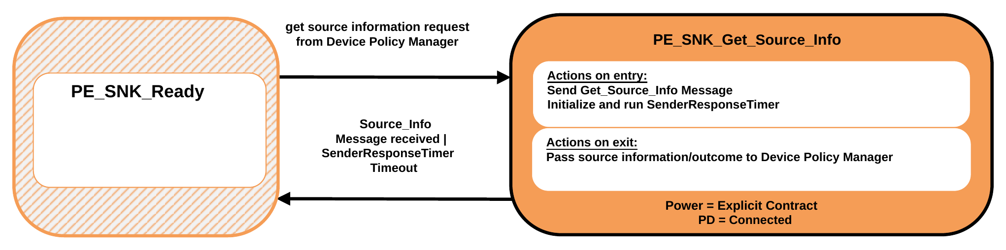
9.2.10.1.1. PE_SNK_Get_Source_Info State
The Policy Engine Shall transition to the PE_SNK_Get_Source_Info State, from the PE_SNK_Ready State, due to a Request to get the remote Source information from the Device Policy Manager.
On entry to the PE_SNK_Get_Source_Info State the Policy Engine Shall send a Get_Source_Info Message and initialize and run the SenderResponseTimer.
On exit from the PE_SNK_Get_Source_Info State the Policy Engine Shall inform the Device Policy Manager of the outcome (information or response timeout).
The Policy Engine Shall transition back to the PE_SNK_Ready State (see Figure 9.18 ) when:
- A Source_Info Message is received
- Or SenderResponseTimer times out.
9.2.10.2. Source Give Source Information State Diagram
Figure 9.34 shows the State diagram for a Source on receiving a Get_Source_Info Message. See also Section 6.3.23 and Section 6.4.10.
Figure 9.34. Source Give Source Information State Diagram
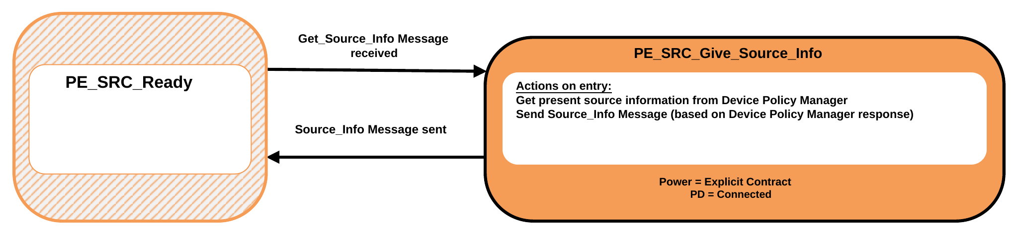
9.2.10.2.1. PE_SRC_Give_Source_Info State
The Policy Engine Shall transition to the PE_SRC_Give_Source_Info State, from the PE_SRC_Ready State, when a Get_Source_Info Message is received.
On entry to the PE_SRC_Give_Source_Info State the Policy Engine Shall Request the present Source information from the Device Policy Manager and then send a Source_Info Message based on this information.
The Policy Engine Shall transition back to the PE_SRC_Ready State (see Figure 9.17 ) when:
- The Source_Info Message has been successfully sent.
9.2.11. Status State Diagrams
9.2.11.1. Get Status State Diagram
Figure 9.35 shows the State diagram for a Port on receiving a Request from the Device Policy Manager to get the Port Partner or Cable Plug's Status. See also Section 6.5.3.
Figure 9.35. Get Status State Diagram
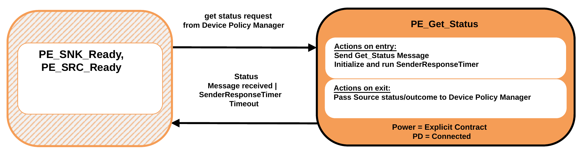
9.2.11.1.1. PE_Get_Status State
The Policy Engine Shall transition to the PE_Get_Status State, from the PE_SRC_Ready or PE_SNK_Ready States, due to a Request to get the Port Partner or Cable Plug's status from the Device Policy Manager.
On entry to the PE_Get_Status State the Policy Engine Shall send a Get_Status Message and initialize and run the SenderResponseTimer.
On exit from the PE_Get_Status State the Policy Engine Shall inform the Device Policy Manager of the outcome (status or response timeout).
The Policy Engine Shall transition back to the PE_SRC_Ready or PE_SNK_Ready States as appropriate (see Figure 9.17 or Figure 9.18 ) when:
- A Status Message is received
- Or SenderResponseTimer times out.
9.2.11.2. Give Status State Diagram
Figure 9.36 shows the State diagram for a Source on receiving a Get_Status Message. See also Section 6.5.3.
Figure 9.36. Give Status State Diagram
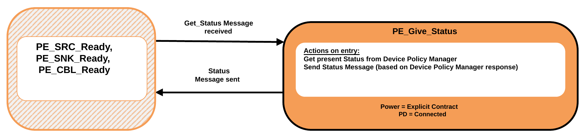
9.2.11.2.1. PE_Give_Status State
The Policy Engine Shall transition to the PE_Give_Status State, from the PE_SRC_Ready, PE_SNK_Ready or PE_CBL_Ready States, when a Get_Status Message is received.
On entry to the PE_Give_Status State the Policy Engine Shall Request the present Source status from the Device Policy Manager and then send a Status Message based on these Capabilities.
The Policy Engine Shall transition back to the PE_SRC_Ready, PE_SNK_Ready or PE_CBL_Ready States as appropriate (see Figure 9.17 , Figure 9.18 and Figure 9.88 ) when:
- The Status Message has been successfully sent.
9.2.11.3. Sink Port Get Source PPS Status State Diagram
Figure 9.37 shows the State diagram for a Sink on receiving a Request from the Device Policy Manager to get the Port Partner's Source status when operating as a PPS. See also Section 6.3.20.
Figure 9.37. Sink Port Get Source PPS Status State Diagram
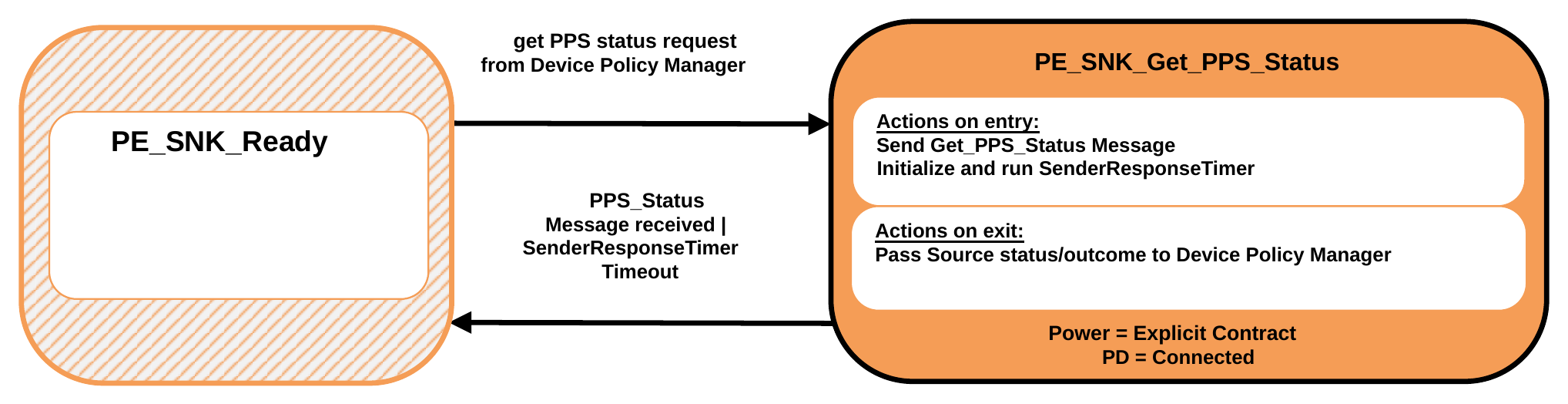
9.2.11.3.1. PE_SNK_Get_PPS_Status State
The Policy Engine Shall transition to the PE_SNK_Get_PPS_Status State, from the PE_SNK_Ready State, due to a Request to get the remote Source PPS status from the Device Policy Manager.
On entry to the PE_SNK_Get_PPS_Status State the Policy Engine Shall send a Get_PPS_Status Message and initialize and run the SenderResponseTimer.
On exit from the PE_SNK_Get_PPS_Status State the Policy Engine Shall inform the Device Policy Manager of the outcome (status or response timeout).
The Policy Engine Shall transition back to the PE_SNK_Ready State (see Figure 9.18 ) when:
- A PPS_Status Message is received
- Or SenderResponseTimer times out.
9.2.11.4. Source Give Source PPS Status State Diagram
Figure 9.38 shows the State diagram for a Source on receiving a Get_PPS_Status Message. See also Section 6.3.20.
Figure 9.38. Source Give Source PPS Status State Diagram
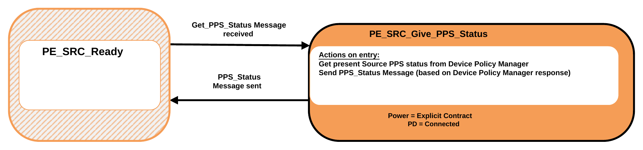
9.2.11.4.1. PE_SRC_Give_PPS_Status State
The Policy Engine Shall transition to the PE_SRC_Give_PPS_Status State, from the PE_SRC_Ready State, when a Get_PPS_Status Message is received.
On entry to the PE_SRC_Give_PPS_Status State the Policy Engine Shall Request the present Source PPS status from the Device Policy Manager and then send a PPS_Status Message based on these Capabilities.
The Policy Engine Shall transition back to the PE_SRC_Ready State (see Figure 9.17 ) when:
- The PPS_Status Message has been successfully sent.
9.2.12. Battery Capabilities State Diagrams
9.2.12.1. Get Battery Capabilities State Diagram
Figure 9.39 shows the State diagram for a Source or Sink on receiving a Request from the Device Policy Manager to get the Port Partner's Battery Capabilities for a specified Battery. See also Section 6.5.6.
Figure 9.39. Get Battery Capabilities State Diagram
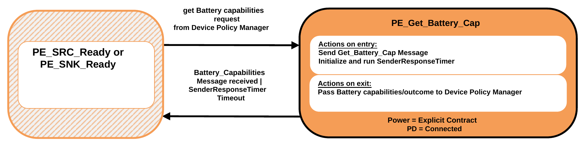
9.2.12.1.1. PE_Get_Battery_Cap State
The Policy Engine Shall transition to the PE_Get_Battery_Cap State, from either the PE_SRC_Ready or PE_SNK_Ready State, due to a Request to get the remote Battery Capabilities, for a specified Battery, from the Device Policy Manager.
On entry to the PE_Get_Battery_Cap State the Policy Engine Shall send a Get_Battery_Cap Message and initialize and run the SenderResponseTimer.
On exit from the PE_Get_Battery_Cap State the Policy Engine Shall inform the Device Policy Manager of the outcome (Capabilities or response timeout).
The Policy Engine Shall transition back to either the PE_SRC_Ready or PE_SNK_Ready State as appropriate (see Figure 9.17 and Figure 9.18 ) when:
- A Battery_Capabilities Message is received
- Or SenderResponseTimer times out.
9.2.12.2. Give Battery Capabilities State Diagram
Figure 9.40 shows the State diagram for a Source or Sink on receiving a Get_Battery_Cap Message. See also Section 6.5.6.
Figure 9.40. Give Battery Capabilities State Diagram
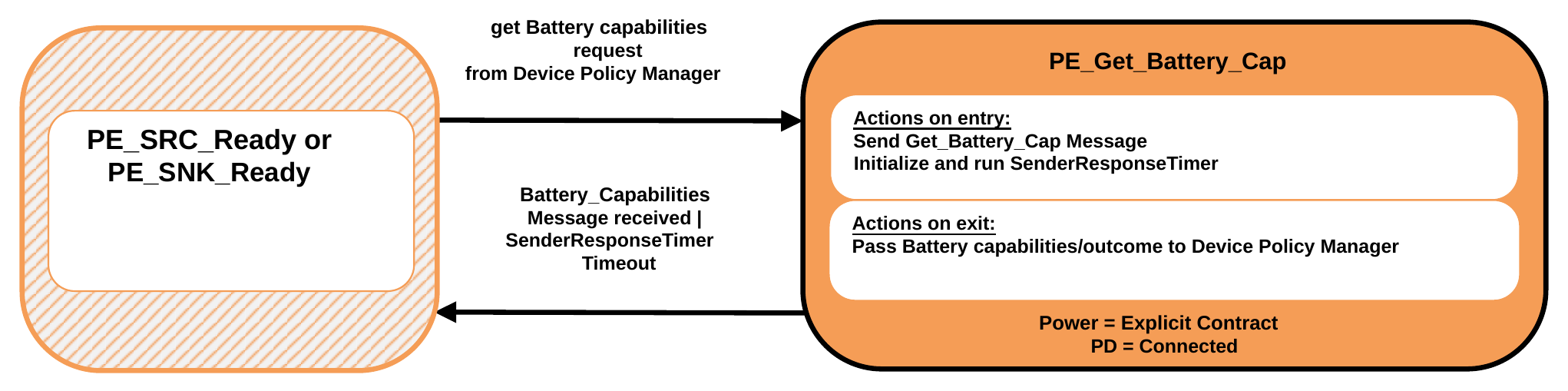
9.2.12.2.1. PE_Give_Battery_Cap State
The Policy Engine Shall transition to the PE_Give_Battery_Cap State, from either the PE_SRC_Ready or PE_SNK_Ready State, when a Get_Battery_Cap Message is received.
On entry to the PE_Give_Battery_Cap State the Policy Engine Shall Request the present Battery Capabilities, for the requested Battery, from the Device Policy Manager and then send a Battery_Capabilities Message based on these Capabilities.
The Policy Engine Shall transition back to either the PE_SRC_Ready or PE_SNK_Ready State as appropriate (see Figure 9.17 and Figure 9.18 ) when:
- The Battery_Capabilities Message has been successfully sent.
9.2.13. Battery Status State Diagrams
9.2.13.1. Get Battery Status State Diagram
Figure 9.41 shows the State diagram for a Source or Sink on receiving a Request from the Device Policy Manager to get the Port Partner's Battery status for a specified Battery. See also Section 6.5.5.
Figure 9.41. Get Battery Status State Diagram
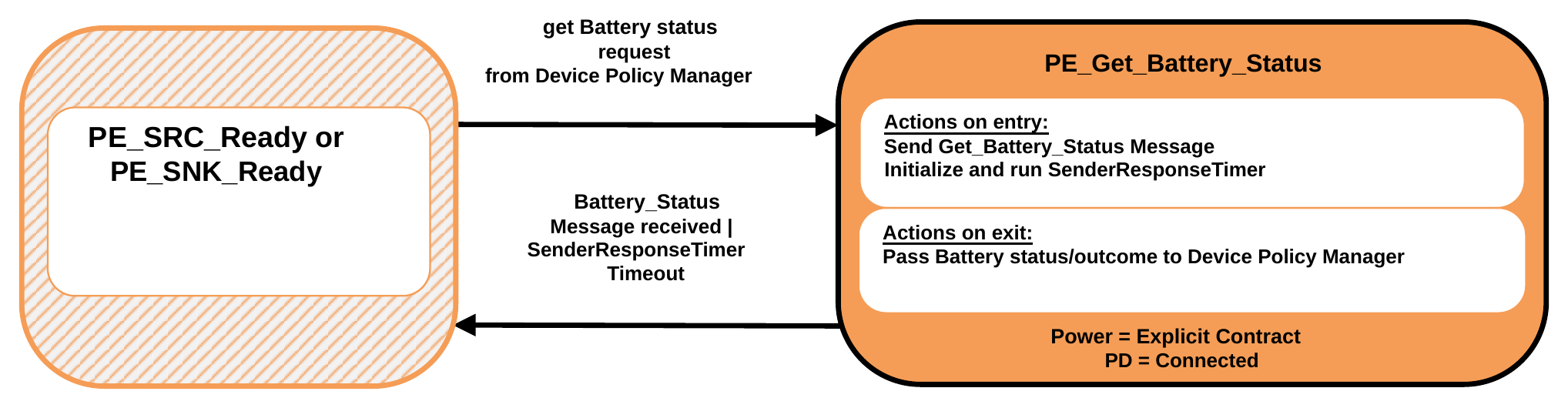
9.2.13.1.1. PE_Get_Battery_Status State
The Policy Engine Shall transition to the PE_Get_Battery_Status State, from either the PE_SRC_Ready or PE_SNK_Ready State, due to a Request to get the remote Battery status, for a specified Battery, from the Device Policy Manager.
On entry to the PE_Get_Battery_Status State the Policy Engine Shall send a Get_Battery_Status Message and initialize and run the SenderResponseTimer.
On exit from the PE_Get_Battery_Status State the Policy Engine Shall inform the Device Policy Manager of the outcome (status or response timeout).
The Policy Engine Shall transition back to either the PE_SRC_Ready or PE_SNK_Ready State as appropriate (see Figure 9.17 and Figure 9.18 ) when:
- A Battery_Status Message is received
- Or SenderResponseTimer times out.
9.2.13.2. Give Battery Status State Diagram
Figure 9.42 shows the State diagram for a Source or Sink on receiving a Get_Battery_Status Message. See also Section 6.5.5.
Figure 9.42. Give Battery Status State Diagram
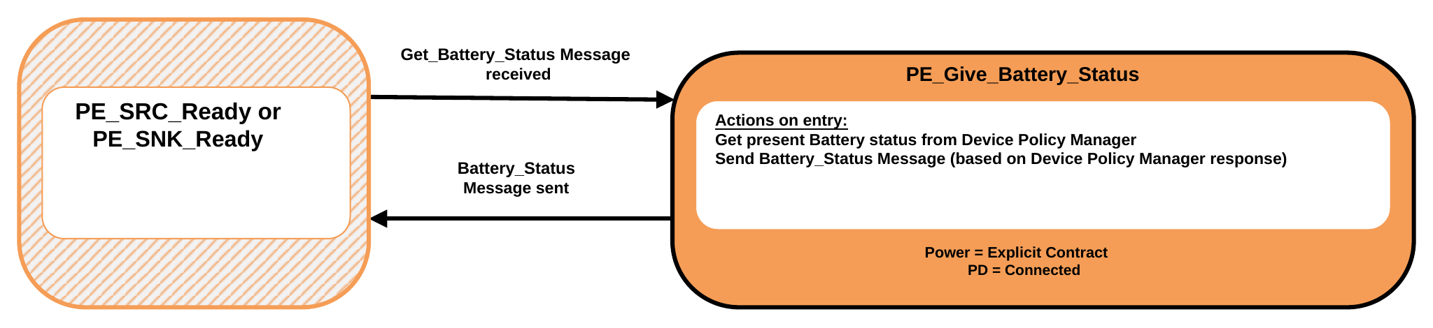
9.2.13.2.1. PE_Give_Battery_Status State
The Policy Engine Shall transition to the PE_Give_Battery_Status State, from either the PE_SRC_Ready or PE_SNK_Ready State, when a Get_Battery_Status Message is received.
On entry to the PE_Give_Battery_Status State the Policy Engine Shall Request the present Battery status, for the requested Battery, from the Device Policy Manager and then send a Battery_Status Message based on this status.
The Policy Engine Shall transition back to either the PE_SRC_Ready or PE_SNK_Ready State as appropriate (see Figure 9.17 and Figure 9.18 ) when:
- The Battery_Status Message has been successfully sent.
9.2.14. Manufacturer Information State Diagrams
9.2.14.1. Get Manufacturer Information State Diagram
Figure 9.43 shows the State diagram for a Source or Sink on receiving a Request from the Device Policy Manager to get the Port Partner or Cable Plug's Manufacturer Information. See also Section 6.5.7.
Figure 9.43. Get Manufacturer Information State Diagram
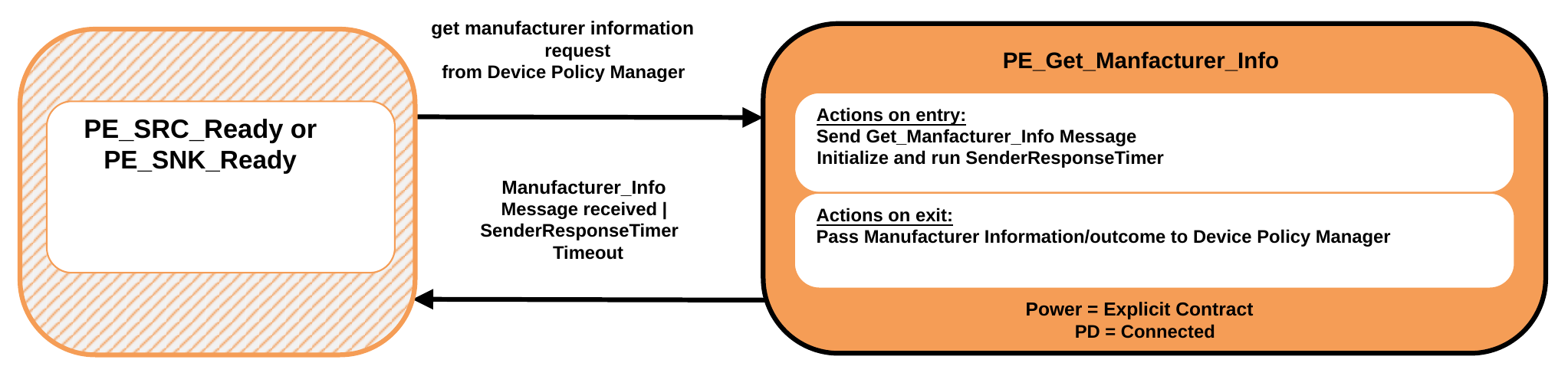
9.2.14.1.1. PE_Get_Manufacturer_Info State
The Policy Engine Shall transition to the PE_Get_Manufacturer_Info State, from either the PE_SRC_Ready or PE_SNK_Ready State, due to a Request to get the remote Manufacturer Information from the Device Policy Manager.
On entry to the PE_Get_Manufacturer_Info State the Policy Engine Shall send a Get_Manufacturer_Info Message and initialize and run the SenderResponseTimer.
On exit from the PE_Get_Manufacturer_Info State the Policy Engine Shall inform the Device Policy Manager of the outcome (information or response timeout). The Policy Engine Shall transition back to either the PE_SRC_Ready or PE_SNK_Ready State as appropriate (see Figure 9.17 and Figure 9.18 ) when:
- A Manufacturer_Info Message is received
- Or SenderResponseTimer times out.
9.2.14.2. Give Manufacturer Information State Diagram
Figure 9.44 shows the State diagram for a Source, Sink or Cable Plug on receiving a Get_Manufacturer_Info Message. See also Section 6.5.7.
Figure 9.44. Give Manufacturer Information State Diagram
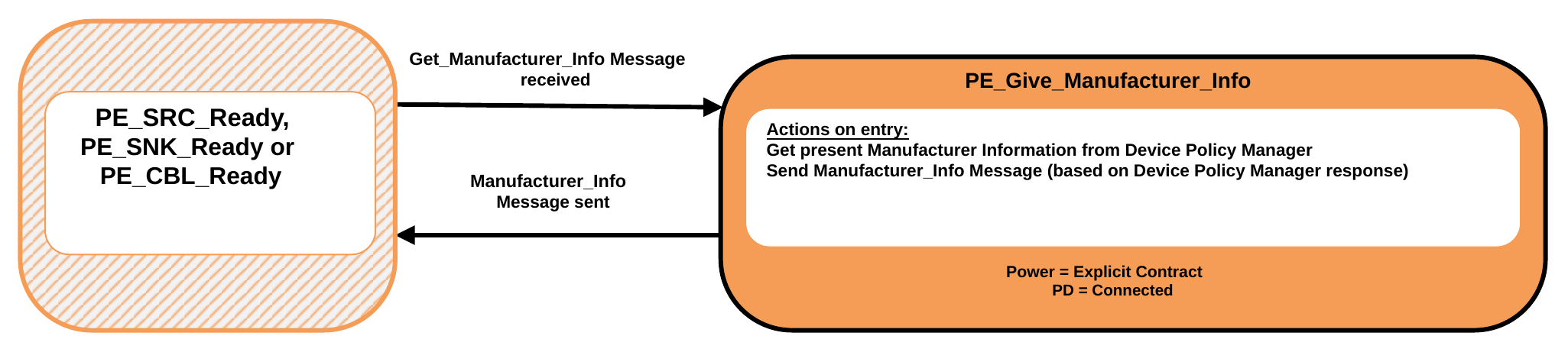
9.2.14.2.1. PE_Give_Manufacturer_Info State
The Policy Engine Shall transition to the PE_Give_Manufacturer_Info State, from either the PE_SRC_Ready, PE_SNK_Ready or PE_CBL_Ready State, when a Get_Manufacturer_Info Message is received.
On entry to the PE_Give_Manufacturer_Info State the Policy Engine Shall Request the manufacturer information from the Device Policy Manager and then send a Manufacturer_Info Message based on this status.
The Policy Engine Shall transition back to either the PE_SRC_Ready, PE_SNK_Ready or PE_CBL_Ready State as appropriate (see Figure 9.17 , Figure 9.18 and Figure 9.88 ) when:
- The Manufacturer_Info Message has been successfully sent.
9.2.15. Country Codes and Information State Diagrams
9.2.15.1. Get Country Codes State Diagram
Figure 9.45 shows the State diagram for a Source or Sink on receiving a Request from the Device Policy Manager to get the Port Partner or Cable Plug's Country Codes. See also Section 6.3.21.
Figure 9.45. Get Country Codes State Diagram
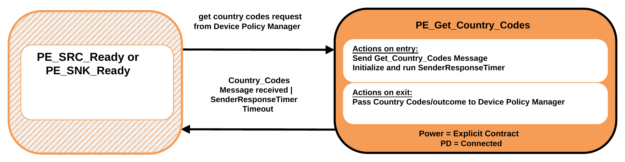
9.2.15.1.1. PE_Get_Country_Codes State
The Policy Engine Shall transition to the PE_Get_Country_Codes State, from either the PE_SRC_Ready or PE_SNK_Ready State, due to a Request to get the remote Country Codes from the Device Policy Manager.
On entry to the PE_Get_Country_Codes State the Policy Engine Shall send a Get_Country_Codes Message and initialize and run the SenderResponseTimer.
On exit from the PE_Get_Country_Codes State the Policy Engine Shall inform the Device Policy Manager of the outcome (Country Codes or response timeout).
The Policy Engine Shall transition back to either the PE_SRC_Ready or PE_SNK_Ready State as appropriate (see Figure 9.17 and Figure 9.18 ) when:
- A Country_Codes Message is received
- Or SenderResponseTimer times out.
9.2.15.2. Give Country Codes State Diagram
Figure 9.46 shows the State diagram for a Source or Sink on receiving a Get_Country_Codes Message. See also Section 6.3.21.
Figure 9.46. Give Country Codes State Diagram
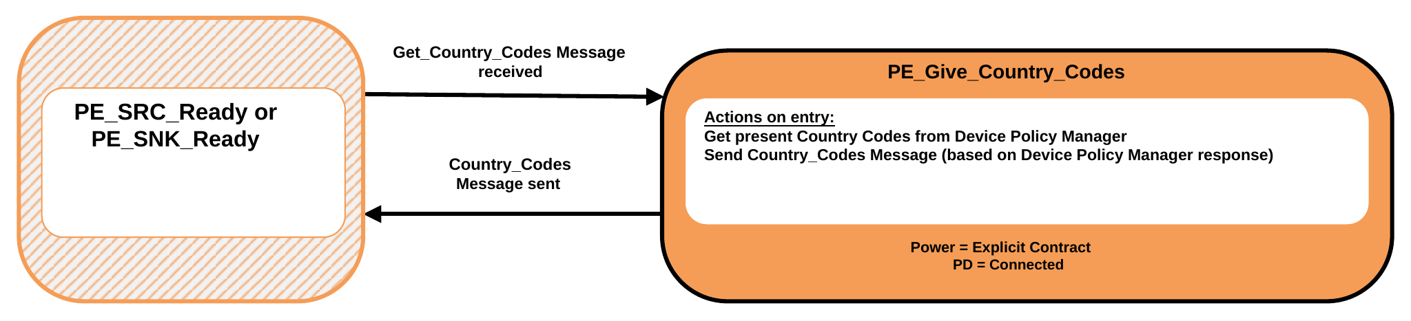
9.2.15.2.1. PE_Give_Country_Codes State
The Policy Engine Shall transition to the PE_Give_Country_Codes State, from either the PE_SRC_Ready or PE_SNK_Ready State, when a Get_Country_Codes Message is received.
On entry to the PE_Give_Country_Codes State the Policy Engine Shall Request the country codes from the Device Policy Manager and then send a Country_Codes Message containing these codes.
The Policy Engine Shall transition back to either the PE_SRC_Ready or PE_SNK_Ready State as appropriate (see Figure 9.17 and Figure 9.18 ) when:
- The Country_Codes Message has been successfully sent.
9.2.15.3. Get Country Information State Diagram
Figure 9.47 shows the State diagram for a Source or Sink on receiving a Request from the Device Policy Manager to get the Port Partner or Cable Plug's Country Information. See also Section 6.4.6.
Figure 9.47. Get Country Information State Diagram
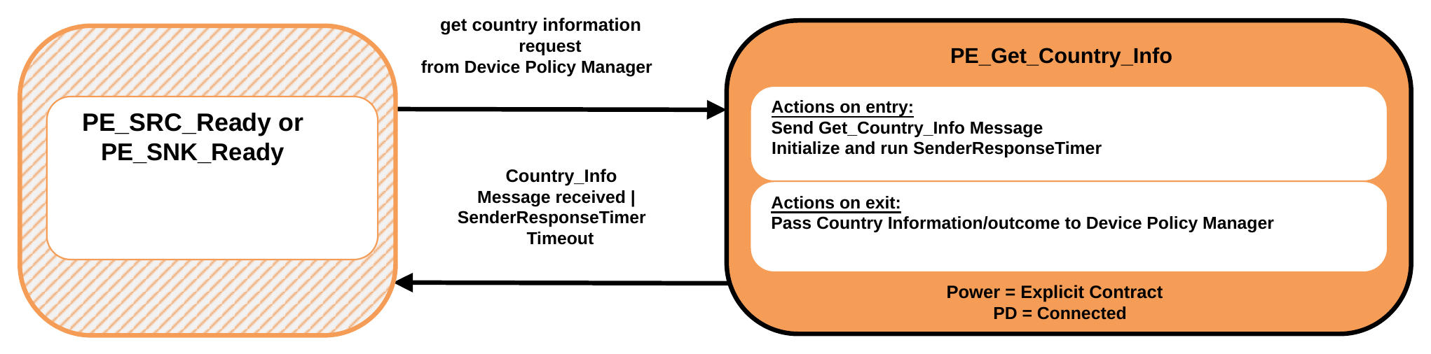
9.2.15.3.1. PE_Get_Country_Info State
The Policy Engine Shall transition to the PE_Get_Country_Info State, from either the PE_SRC_Ready or PE_SNK_Ready State, due to a Request to get the remote Manufacturer Information from the Device Policy Manager.
On entry to the PE_Get_Country_Info State the Policy Engine Shall send a Get_Manufacturer_Info Message and initialize and run the SenderResponseTimer.
On exit from the PE_Get_Country_Info State the Policy Engine Shall inform the Device Policy Manager of the outcome (country information or response timeout).
The Policy Engine Shall transition back to either the PE_SRC_Ready or PE_SNK_Ready State as appropriate (see Figure 9.17 and Figure 9.18 ) when:
- A Country_Info Message is received
- Or SenderResponseTimer times out.
9.2.15.4. Give Country Information State Diagram
Figure 9.48 shows the State diagram for a Source or Sink on receiving a Get_Country_Info Message. See also Section 6.4.6.
Figure 9.48. Give Country Information State Diagram
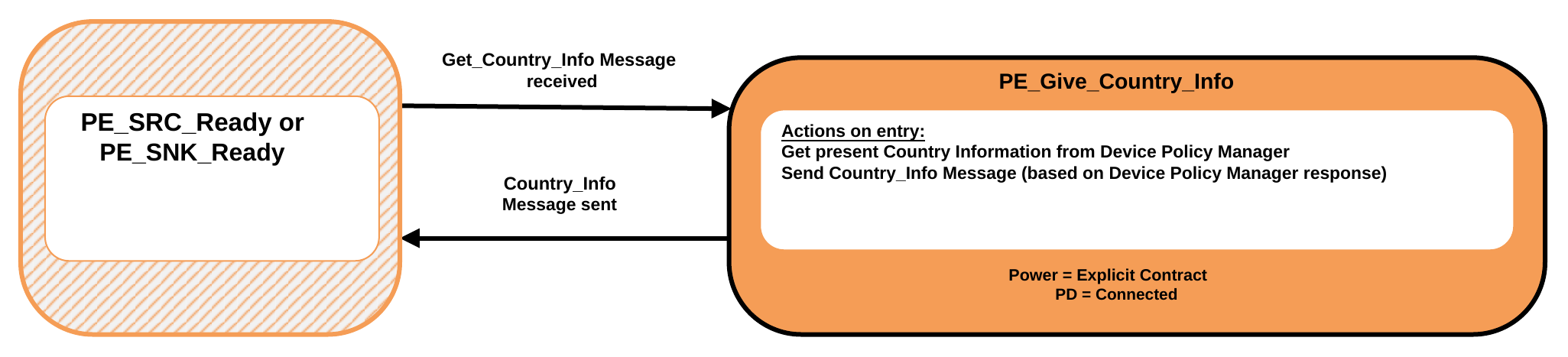
9.2.15.4.1. PE_Give_Country_Info State
The Policy Engine Shall transition to the PE_Give_Country_Info State, from either the PE_SRC_Ready or PE_SNK_Ready State, when a Get_Country_Info Message is received.
On entry to the PE_Give_Country_Info State the Policy Engine Shall Request the country information from the Device Policy Manager and then send a Country_Info Message containing this country information.
The Policy Engine Shall transition back to either the PE_SRC_Ready or PE_SNK_Ready State as appropriate (see Figure 9.17 and Figure 9.18 ) when:
- The Country_Info Message has been successfully sent.
9.2.16. Revision State Diagrams
9.2.16.1. Get Revision State Diagram
Figure 9.49 shows the State diagram for a Source or Sink on receiving a Request from the Device Policy Manager to get the Port Partner or Cable Plug's Revision Information. See also Section 6.3.24 and Section 6.4.11.
Figure 9.49. Get Revision State Diagram
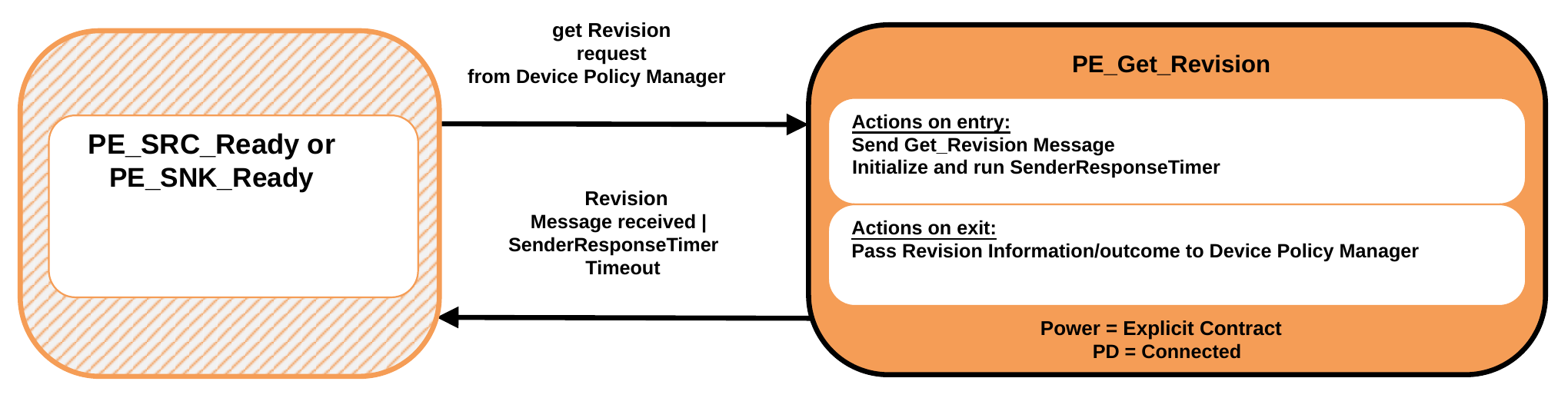
9.2.16.1.1. PE_Get_Revision State
The Policy Engine Shall transition to the PE_Get_Revision State, from either the PE_SRC_Ready or PE_SNK_Ready State, due to a Request to get the remote Revision Information from the Device Policy Manager.
On entry to the PE_Get_Revision State the Policy Engine Shall send a Get_Revision Message and initialize and run the SenderResponseTimer.
On exit from the PE_Get_Revision State the Policy Engine Shall inform the Device Policy Manager of the outcome (Revision information or response timeout).
The Policy Engine Shall transition back to either the PE_SRC_Ready or PE_SNK_Ready State as appropriate (see Figure 9.17 and Figure 9.18 ) when:
- A Revision Message is received
- Or SenderResponseTimer times out.
9.2.16.2. Give Revision State Diagram
Figure 9.50 shows the State diagram for a Source, Sink or Cable Plug on receiving a Get_Revision Message. See also Section 6.3.24 and Section 6.4.11.
Figure 9.50. Give Revision State Diagram
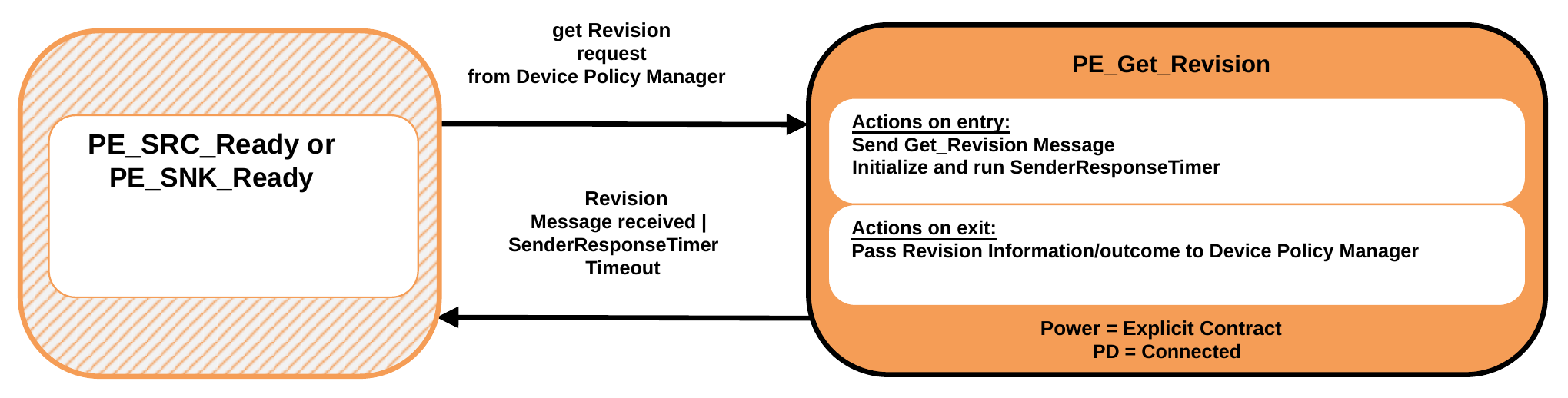
9.2.16.2.1. PE_Give_Revision State
The Policy Engine Shall transition to the PE_Give_Revision State, from either the PE_SRC_Ready, PE_SNK_Ready or PE_CBL_Ready State, when a Get_Revision Message is received.
On entry to the PE_Give_Revision State the Policy Engine Shall Request the Revision information from the Device Policy Manager and then send a Revision Message based on this information.
The Policy Engine Shall transition back to either the PE_SRC_Ready, PE_SNK_Ready or PE_CBL_Ready State as appropriate (see Figure 9.17 , Figure 9.18 and Figure 9.88 ) when:
- The Revision Message has been successfully sent.
9.2.17. Enter_USB Message State Diagrams
9.2.17.1. DFP Enter_USB Message State Diagrams
Figure 9.51 shows the State diagram for an Enter_USB Message sent by a DFP.
Figure 9.51. DFP Enter_USB Message State Diagram
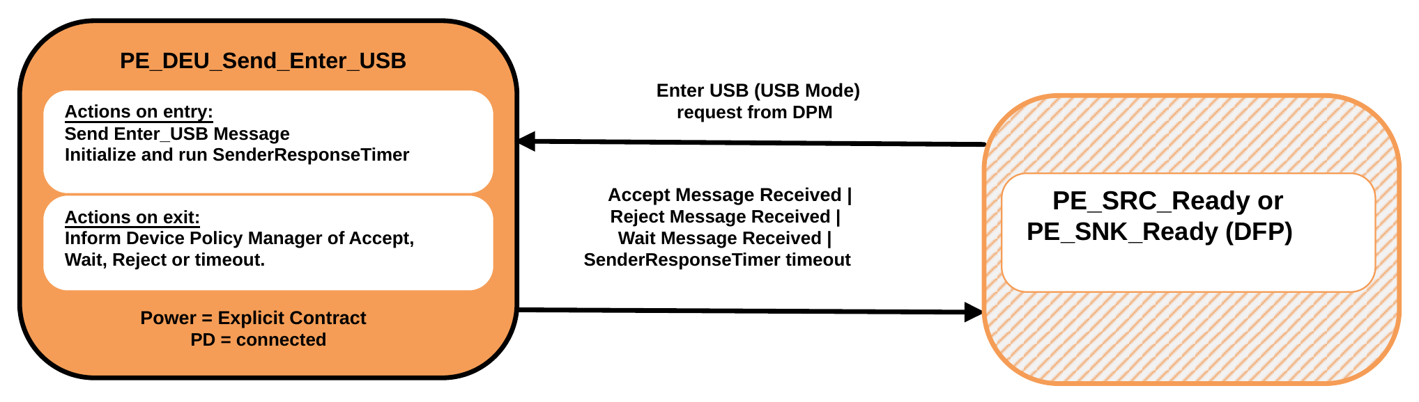
9.2.17.1.1. PE_DEU_Send_Enter_USB State
The PE_DEU_Send_Enter_USB State Shall be entered from the PE_SRC_Ready or PE_SNK_Ready State when requested by the Device Policy Manager and the Port is operating as a DFP. On entry to the PE_DEU_Send_Enter_USB State the Policy Engine Shall Request the Protocol Layer to send an Enter_USB Message and then initialize and run the SenderResponseTimer.
On exit from the PE_DEU_Send_Enter_USB State the Policy Engine Shall inform the Device Policy Manager of the outcome: Accept Message received, Reject Message received, SenderResponseTimer timeout.
The Policy Engine Shall transition back to the PE_SRC_Ready or PE_SNK_Ready State depending on the Ports Power Role when:
- An Accept Message has been received or
- A Wait Message has been received or
- A Reject Message has been received
- There is a SenderResponseTimer timeout.
9.2.17.2. UFP or Cable Plug Enter_USB Message State Diagrams
Figure 9.52 shows the State diagram for an Enter_USB Message received by a UFP or Cable Plug.
Figure 9.52. UFP Enter_USB Message State Diagram

9.2.17.2.1. PE_UEU_Enter_USB_Received State
The PE_UEU_Enter_USB_Received State Shall be entered from the PE_SRC_Ready, PE_SNK_Ready or PE_CBL_Ready State as appropriate (see Figure 9.17, Figure 9.18 and Figure 9.88 ) when an Enter_USB Message is received and the Port is operating as a UFP or is a Cable Plug.
On entry to the PE_UEU_Enter_USB_Received State the Policy Engine Shall inform the Device Policy Manager. The Device Policy Manager responds with an indication of whether the Enter_USB Message is to be accepted or rejected. The Policy Engine Shall send either an Accept Message, a Wait Message or a Reject Message as appropriate.
The Policy Engine Shall transition back to the PE_SRC_Ready, PE_SNK_Ready or PE_CBL_Ready State as appropriate when:
- Either an Accept Message, a Wait Message or a Reject Message has been sent.
9.2.18. Security State Diagrams
9.2.18.1. Send Security Request State Diagram
Figure 9.53 shows the State diagram for a Source or Sink on receiving a Request from the Device Policy Manager to send a security Request.
Figure 9.53. Send security Request State Diagram
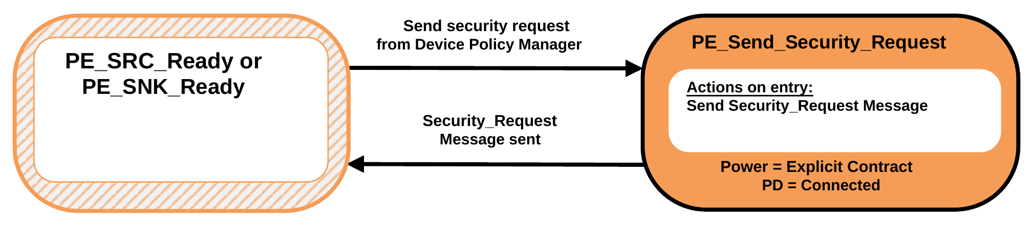
9.2.18.1.1. PE_Send_Security_Request State
The Policy Engine Shall transition to the PE_Send_Security_Request State, from either the PE_SRC_Ready or PE_SNK_Ready State, due to a Request to send a security Request from the Device Policy Manager.
On entry to the PE_Send_Security_Request State the Policy Engine Shall send a Security_Request Message.
The Policy Engine Shall transition back to either the PE_SRC_Ready or PE_SNK_Ready State as appropriate (see Figure 9.17 and Figure 9.18 ) when:
- The Security_Request Message has been sent.
9.2.18.2. Send Security Response State Diagram
Figure 9.54 shows the State diagram for a Source, Sink or Cable Plug on receiving a Security_Request Message. See also Section 6.5.9.
Figure 9.54. Send security response State Diagram
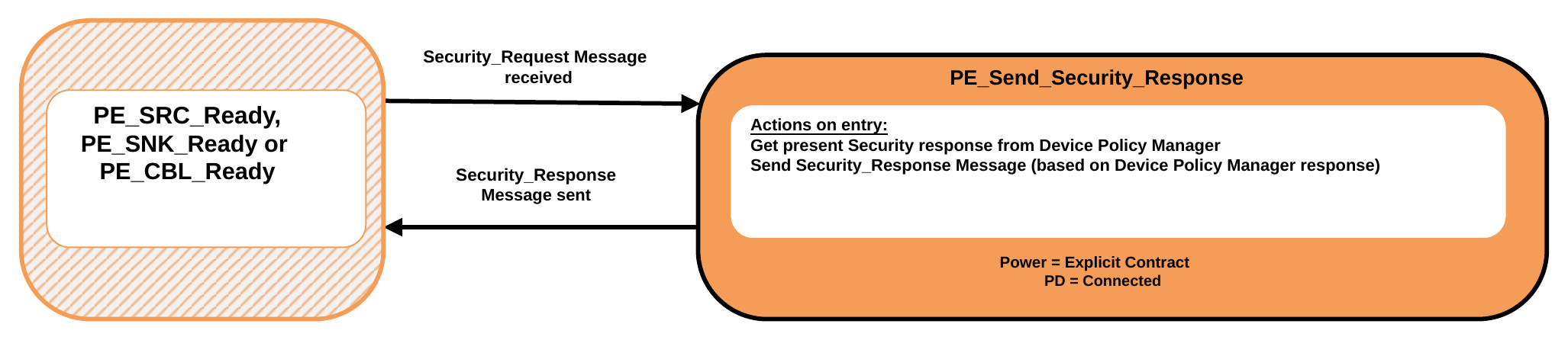
9.2.18.2.1. PE_Send_Security_Response State
The Policy Engine Shall transition to the PE_Send_Security_Response State, from either the PE_SRC_Ready, PE_SNK_Ready or PE_CBL_Ready State, when a Security_Request Message is received.
On entry to the PE_Send_Security_Response State the Policy Engine Shall Request the appropriate response from the Device Policy Manager and then send a Security_Response Message based on this status.
The Policy Engine Shall transition back to either the PE_SRC_Ready, PE_SNK_Ready or PE_CBL_Ready State as appropriate (see Figure 9.17 , Figure 9.18 and Figure 9.88 ) when:
- The Security_Response Message has been successfully sent.
9.2.18.3. Security Response Received State Diagram
Figure 9.55 shows the State diagram for a Source or Sink on receiving a Security_Response Message. See also Section 6.5.10.
Figure 9.55. Security response received State Diagram
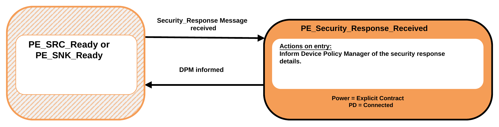
9.2.18.3.1. PE_Security_Response_Received State
The Policy Engine Shall transition to the PE_Security_Response_Received State, from either the PE_SRC_Ready or PE_SNK_Ready when a Security_Response Message is received.
On entry to the PE_Security_Response_Received State the Policy Engine Shall inform the Device Policy Manager of the details of the security response.
The Policy Engine Shall transition back to either the PE_SRC_Ready or PE_SNK_Ready State as appropriate (see Figure 9.17 , Figure 9.18 and Figure 9.88 ) when:
- The Device Policy Manager has been informed.
9.2.19. Firmware Update State Diagrams
9.2.19.1. Send Firmware Update Request State Diagram
Figure 9.56 shows the State diagram for a Source or Sink on receiving a Request from the Device Policy Manager to send a firmware update Request.
Figure 9.56. Send firmware update Request State Diagram
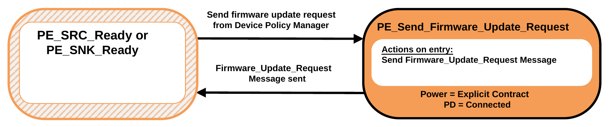
9.2.19.1.1. PE_Send_Firmware_Update_Request State
The Policy Engine Shall transition to the PE_Send_Firmware_Update_Request State, from either the PE_SRC_Ready or PE_SNK_Ready State, due to a Request to send a firmware update Request from the Device Policy Manager.
On entry to the PE_Send_Firmware_Update_Request State the Policy Engine Shall send a Firmware_Update_Request Message.
The Policy Engine Shall transition back to either the PE_SRC_Ready or PE_SNK_Ready State as appropriate (see Figure 9.17 and Figure 9.18 ) when:
- The Firmware_Update_Request Message has been sent.
9.2.19.2. Send Firmware Update Response State Diagram
Figure 9.57 shows the State diagram for a Source, Sink or Cable Plug on receiving a Firmware_Update_Request Message. See also Section 6.5.11.
Figure 9.57. Send firmware update response State Diagram
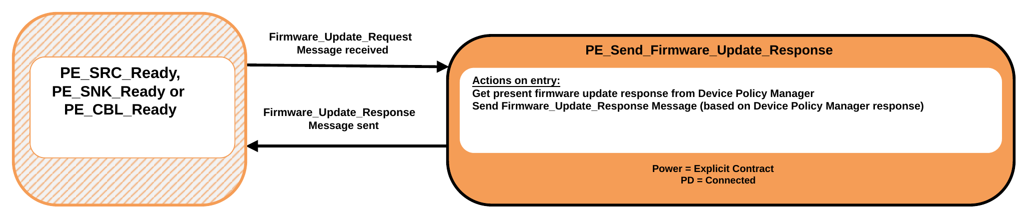
9.2.19.2.1. PE_Send_Firmware_Update_Response State
The Policy Engine Shall transition to the PE_Send_Firmware_Update_Response State, from either the PE_SRC_Ready, PE_SNK_Ready or PE_CBL_Ready State, when a Firmware_Update_Request Message is received.
On entry to the PE_Send_Firmware_Update_Response State the Policy Engine Shall Request the appropriate response from the Device Policy Manager and then send a Firmware_Update_Response Message based on this status.
The Policy Engine Shall transition back to either the PE_SRC_Ready, PE_SNK_Ready or PE_CBL_Ready State as appropriate (see Figure 9.17 , Figure 9.18 and Figure 9.88 ) when:
- The Firmware_Update_Response Message has been successfully sent.
9.2.19.3. Firmware Update Response Received State Diagram
Figure 9.58 shows the State diagram for a Source or Sink on receiving a Firmware_Update_Response Message. See also Section 6.5.12.
Figure 9.58. Firmware update response received State Diagram
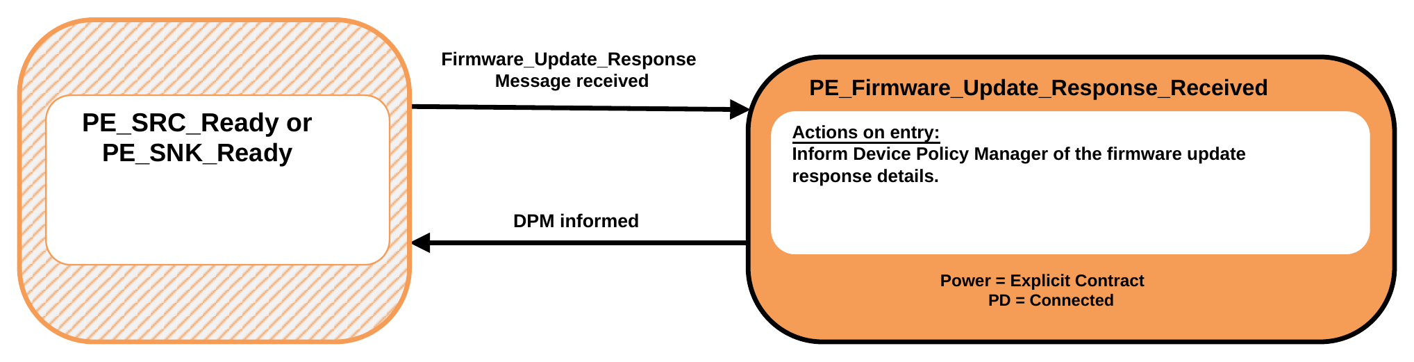
9.2.19.3.1. PE_Firmware_Update_Response_Received State
The Policy Engine Shall transition to the PE_Firmware_Update_Response_Received State, from either the PE_SRC_Ready or PE_SNK_Ready when a Firmware_Update_Response Message is received.
On entry to the PE_Firmware_Update_Response_Received State the Policy Engine Shall inform the Device Policy Manager of the details of the firmware update response.
The Policy Engine Shall transition back to either the PE_SRC_Ready or PE_SNK_Ready State as appropriate (see Figure 9.17 , Figure 9.18 and Figure 9.88 ) when:
- The Device Policy Manager has been informed.
9.2.20. Dual-Role Port State Diagrams
Dual-Role Ports that combine Source and Sink functionality Shall comprise Source and Sink Policy Engine State machines. In addition they Shall have the capability to perform a Power Role Swap from the PE_SRC_Ready or PE_SNK_Ready states and Shall return to USB Default Operation on a Hard Reset.
The State Diagrams in this section Shall apply to every [USB-C] DRP.
9.2.20.1. DFP to UFP Data Role Swap State Diagram
Figure 9.59 shows the additional State diagram required to perform a Data Role Swap from DFP to UFP operation and the changes that Shall be followed for error and Hard Reset handling.
Figure 9.59. DFP to UFP Data Role Swap State Diagram
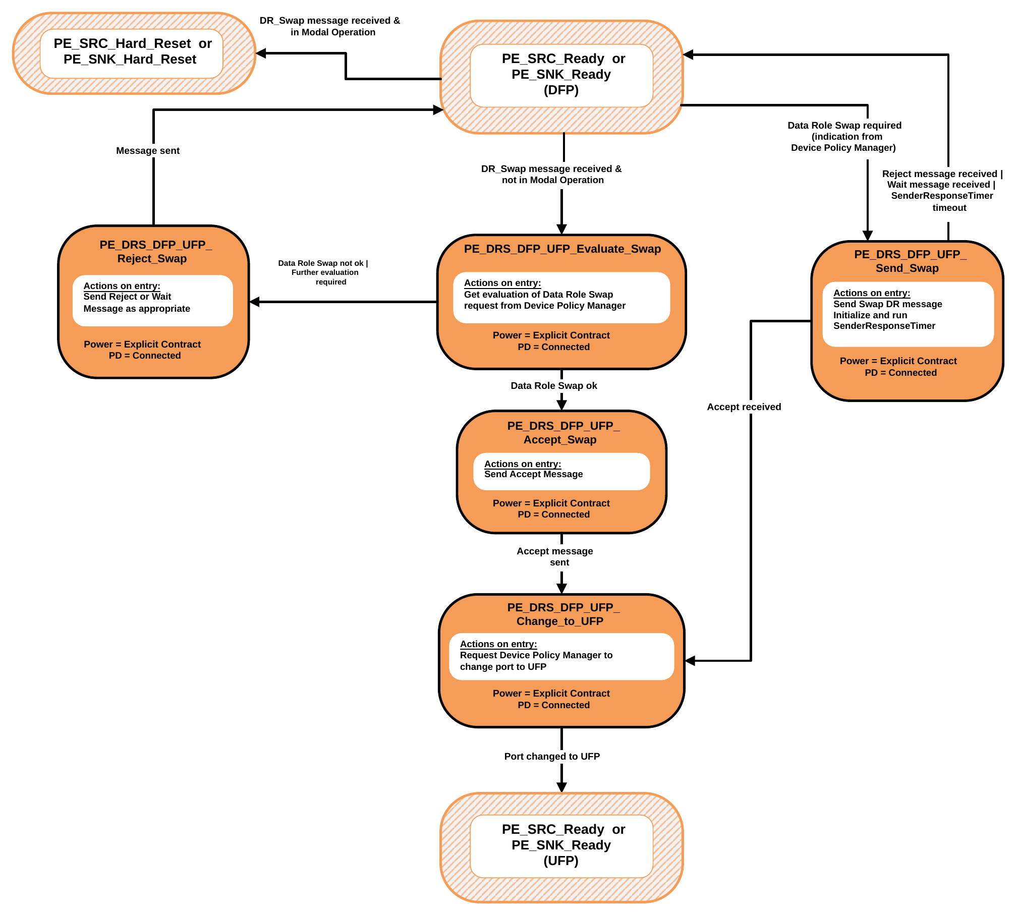
9.2.20.1.1. PE_SRC_Ready or PE_SNK_Ready State
The Data Role Swap process Shall start only from either the PE_SRC_Ready or PE_SNK_Ready State where power is stable.
The Policy Engine Shall transition to the PE_DRS_DFP_UFP_Evaluate_Swap State when:
- A DR_Swap Message is received and
- There are no Active Modes (not in Modal Operation).
The Policy Engine Shall transition to either the PE_SRC_Hard_Reset or PE_SNK_Hard_Reset states when:
- A DR_Swap Message is received and
- There are one or more Active Modes (Modal Operation).
The Policy Engine Shall transition to the PE_DRS_DFP_UFP_Send_Swap State when:
- The Device Policy Manager indicates that a Data Role Swap is required.
9.2.20.1.2. PE_DRS_DFP_UFP_Evaluate_Swap State
On entry to the PE_DRS_DFP_UFP_Evaluate_Swap State the Policy Engine Shall ask the Device Policy Manager whether a Data Role Swap can be made.
The Policy Engine Shall transition to the PE_DRS_DFP_UFP_Accept_Swap State when:
- The Device Policy Manager indicates that a Data Role Swap is OK.
The Policy Engine Shall transition to the PE_DRS_DFP_UFP_Reject_Swap State when:
- The Device Policy Manager indicates that a Data Role Swap is not OK.
- Or further evaluation of the Data Role Swap Request is needed.
9.2.20.1.3. PE_DRS_DFP_UFP_Accept_Swap State
On entry to the PE_DRS_DFP_UFP_Accept_Swap State the Policy Engine Shall Request the Protocol Layer to send an Accept Message.
The Policy Engine Shall transition to the PE_DRS_DFP_UFP_Change_to_UFP State when:
- The Accept Message has been sent.
9.2.20.1.4. PE_DRS_DFP_UFP_Change_to_UFP State
On entry to the PE_DRS_DFP_UFP_Change_to_UFP State the Policy Engine Shall Request the Device Policy Manager to change the Port from a DFP to a UFP.
The Policy Engine Shall transition to either the PE_SRC_Ready or PE_SNK_Ready State when:
- The Device Policy Manager indicates that the Port has been changed to a UFP.
9.2.20.1.5. PE_DRS_DFP_UFP_Send_Swap State
On entry to the PE_DRS_DFP_UFP_Send_Swap State the Policy Engine Shall Request the Protocol Layer to send a DR_Swap Message and Shall start the SenderResponseTimer.
On exit from the PE_DRS_DFP_UFP_Send_Swap State the Policy Engine Shall stop the SenderResponseTimer.
The Policy Engine Shall continue as a DFP and Shall transition to either the PE_SRC_Ready or PE_SNK_Ready State when:
- A Reject Message is received.
- Or a Wait Message is received.
- Or the SenderResponseTimer times out.
The Policy Engine Shall transition to the PE_DRS_DFP_UFP_Change_to_UFP State when:
- An Accept Message is received.
9.2.20.1.6. PE_DRS_DFP_UFP_Reject_Swap State
On entry to the PE_DRS_DFP_UFP_Reject_Swap State the Policy Engine Shall Request the Protocol Layer to send:
- A Reject Message if the Device is unable to perform a Data Role Swap at this time.
- A Wait Message if further evaluation of the Data Role Swap Request is required.
Note: In this case it is expected that one of the Port Partners will send a DR_Swap Message at a later time (see Section 7.12.2).
The Policy Engine Shall continue as a DFP and Shall transition to either the PE_SRC_Ready or PE_SNK_Ready State when:
- The Reject or Wait Message has been sent.
9.2.20.2. UFP to DFP Data Role Swap State Diagram
Figure 9.60 shows the additional State diagram required to perform a Data Role Swap from DRP UFP to DFP operation and the changes that Shall be followed for error and Hard Reset handling.
Figure 9.60. UFP to DFP Data Role Swap State Diagram
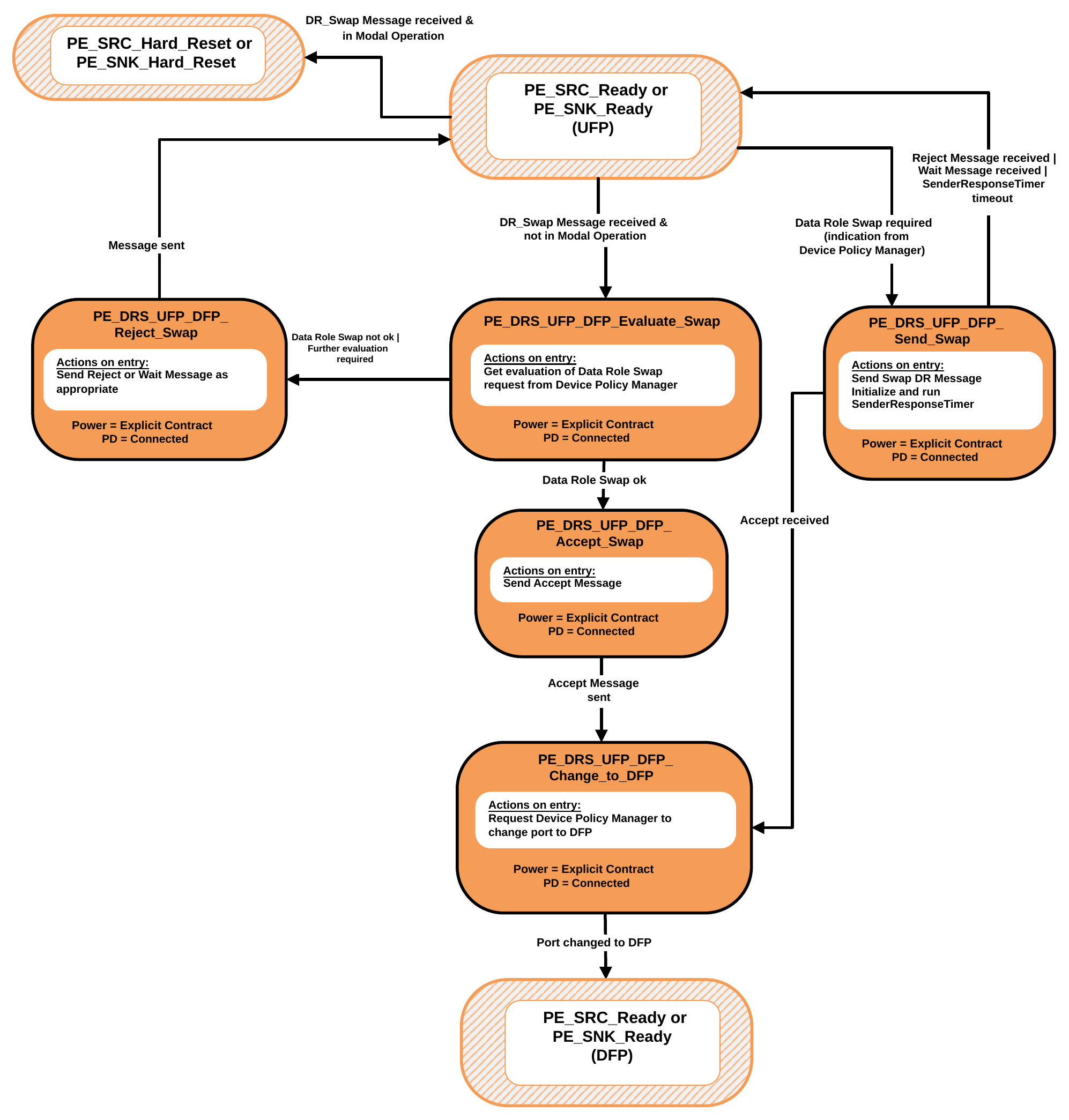
9.2.20.2.1. PE_SRC_Ready or PE_SNK_Ready State
The Data Role Swap process Shall start only from the either the PE_SRC_Ready or PE_SNK_Ready State where power is stable.
The Policy Engine Shall transition to the PE_DRS_UFP_DFP_Evaluate_Swap State when:
- A DR_Swap Message is received and
- There are no Active Modes (not in Modal Operation).
The Policy Engine Shall transition to either the PE_SRC_Hard_Reset or PE_SNK_Hard_Reset states when:
- A DR_Swap Message is received and
- There are one or more Active Modes (Modal Operation).
The Policy Engine Shall transition to the PE_DRS_UFP_DFP_Send_Swap State when:
- The Device Policy Manager indicates that a Data Role Swap is required.
9.2.20.2.2. PE_DRS_UFP_DFP_Evaluate_Swap State
On entry to the PE_DRS_UFP_DFP_Evaluate_Swap State the Policy Engine Shall ask the Device Policy Manager whether a Data Role Swap can be made.
The Policy Engine Shall transition to the PE_DRS_UFP_DFP_Accept_Swap State when:
- The Device Policy Manager indicates that a Data Role Swap is OK.
The Policy Engine Shall transition to the PE_DRS_UFP_DFP_Reject_Swap State when:
- The Device Policy Manager indicates that a Data Role Swap is not OK.
- Or further evaluation of the Data Role Swap Request is needed.
9.2.20.2.3. PE_DRS_UFP_DFP_Accept_Swap State
On entry to the PE_DRS_UFP_DFP_Accept_Swap State the Policy Engine Shall Request the Protocol Layer to send an Accept Message.
The Policy Engine Shall transition to the PE_DRS_UFP_DFP_Change_to_DFP State when:
- The Accept Message has been sent.
9.2.20.2.4. PE_DRS_UFP_DFP_Change_to_DFP State
On entry to the PE_DRS_UFP_DFP_Change_to_DFP State the Policy Engine Shall Request the Device Policy Manager to change the Port from a UFP to a DFP.
The Policy Engine Shall transition to either the PE_SRC_Ready or PE_SNK_Ready State when:
- The Device Policy Manager indicates that the Port has been changed to a DFP.
9.2.20.2.5. PE_DRS_UFP_DFP_Send_Swap State
On entry to the PE_DRS_UFP_DFP_Send_Swap State the Policy Engine Shall Request the Protocol Layer to send a DR_Swap Message and Shall start the SenderResponseTimer.
On exit from the PE_DRS_UFP_DFP_Send_Swap State the Policy Engine Shall stop the SenderResponseTimer.
The Policy Engine Shall continue as a UFP and Shall transition to either the PE_SRC_Ready or PE_SNK_Ready State when:
- A Reject Message is received.
- Or a Wait Message is received.
- Or the SenderResponseTimer times out.
The Policy Engine Shall transition to the PE_DRS_UFP_DFP_Change_to_DFP State when:
- An Accept Message is received.
9.2.20.2.6. PE_DRS_UFP_DFP_Reject_Swap State
On entry to the PE_DRS_UFP_DFP_Reject_Swap State the Policy Engine Shall Request the Protocol Layer to send:
- A Reject Message if the Device is unable to perform a Data Role Swap at this time.
- A Wait Message if further evaluation of the Data Role Swap Request is required.
Note: In this case it is expected that one of the Port Partners will send a DR_Swap Message at a later time (see Section 7.12.2).
The Policy Engine Shall continue as a UFP and Shall transition to the either the PE_SRC_Ready or PE_SNK_Ready State when:
- The Reject or Wait Message has been sent.
9.2.20.3. Policy Engine in Source to Sink Power Role Swap State Diagram
Dual-Role Ports that combine Source and Sink functionality Shall comprise Source and Sink Policy Engine State machines. In addition, they Shall have the capability to do a Power Role Swap from the PE_SRC_Ready State and Shall return to USB Default Operation on a Hard Reset.
Figure 9.61 shows the additional State diagram required to perform a Power Role Swap from Source to Sink Power Roles and the changes that Shall be followed for error handling.
Figure 9.61. Dual-Role Port in Source to Sink Power Role Swap State Diagram
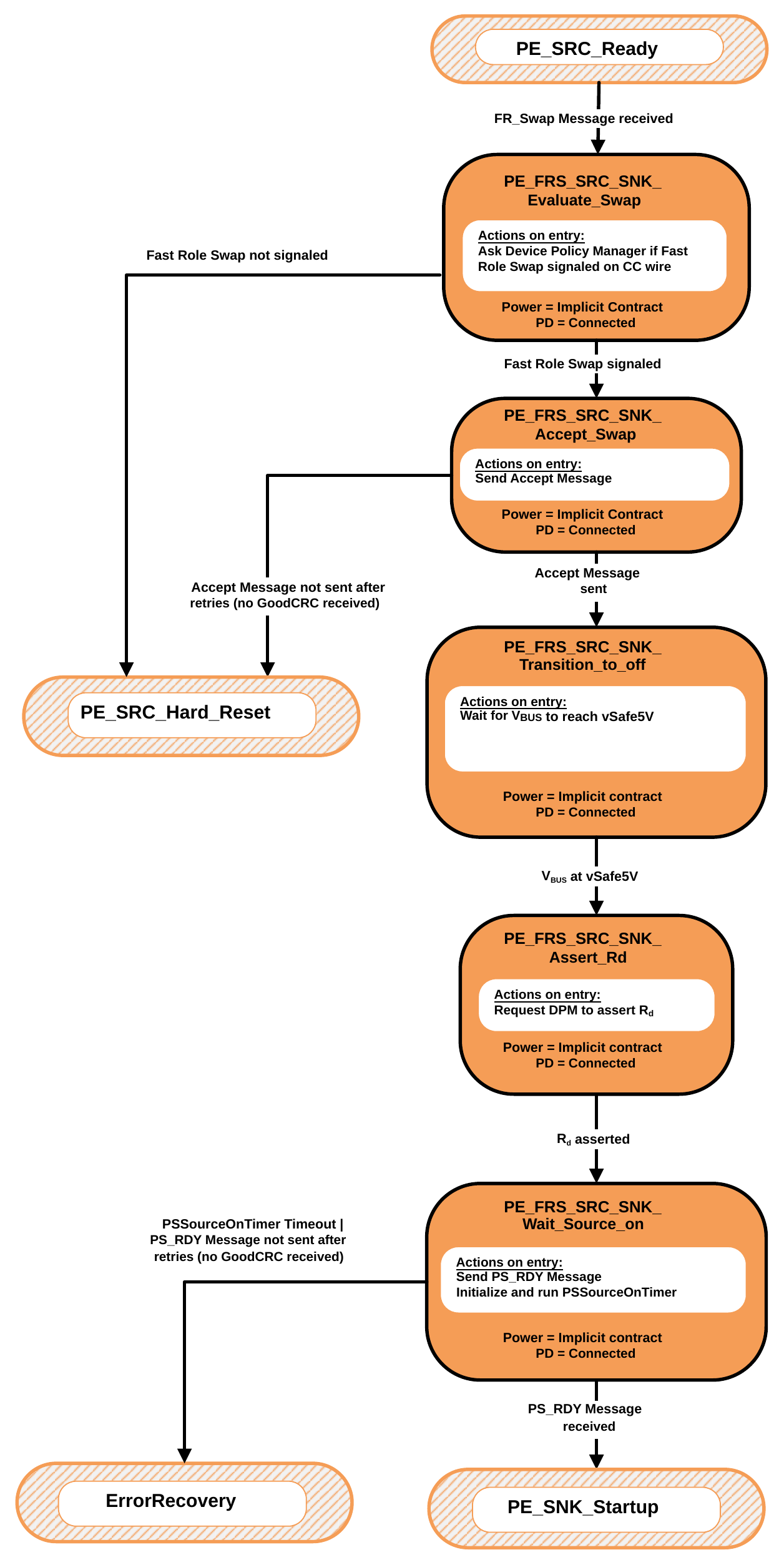
9.2.20.3.1. PE_SRC_Ready State
The Power Role Swap process Shall start only from the PE_SRC_Ready State where power is stable. The Policy Engine Shall transition to the PE_PRS_SRC_SNK_Evaluate_Swap State when:
- A PR_Swap Message is received.
The Policy Engine Shall transition to the PE_PRS_SRC_SNK_Send_Swap State when:
- The Device Policy Manager indicates that a Power Role Swap is required.
9.2.20.3.2. PE_PRS_SRC_SNK_Evaluate_Swap State
On entry to the PE_PRS_SRC_SNK_Evaluate_Swap State the Policy Engine Shall ask the Device Policy Manager whether a Power Role Swap can be made.
The Policy Engine Shall transition to the PE_PRS_SRC_SNK_Accept_Swap State when:
- The Device Policy Manager indicates that a Power Role Swap is OK.
The Policy Engine Shall transition to the PE_PRS_SRC_SNK_Reject_Swap State when:
-
The Device Policy Manager indicates that a Power Role Swap is not OK.
-
Or further evaluation of the Power Role Swap Request is needed.
9.2.20.3.3. PE_PRS_SRC_SNK_Accept_Swap State
On entry to the PE_PRS_SRC_SNK_Accept_Swap State the Policy Engine Shall Request the Protocol Layer to send an Accept Message.
The Policy Engine Shall transition to the PE_PRS_SRC_SNK_Transition_to_off State when:
- The Accept Message has been sent.
9.2.20.3.4. PE_PRS_SRC_SNK_Transition_to_off State
On entry to the PE_PRS_SRC_SNK_Transition_to_off State the Policy Engine Shall Request the Device Policy Manager to turn off the Source.
The Policy Engine Shall transition to the PE_PRS_SRC_SNK_Assert_Rd State when:
- The Device Policy Manager indicates that the Source has been turned off.
9.2.20.3.5. PE_PRS_SRC_SNK_Assert_Rd State
On entry to the PE_PRS_SRC_SNK_Assert_Rd State the Policy Engine Shall Request the Device Policy Manager to change the resistor asserted on the CC wire from Rp to Rd.
The Policy Engine Shall transition to the PE_PRS_SRC_SNK_Wait_Source_on State when:
- The Device Policy Manager indicates that Rd is asserted.
9.2.20.3.6. PE_PRS_SRC_SNK_Wait_Source_on State
On entry to the PE_PRS_SRC_SNK_Wait_Source_on State the Policy Engine Shall Request the Protocol Layer to send a PS_RDY Message and Shall start the PSSourceOnTimer.
On exit from the Source off State the Policy Engine Shall stop the PSSourceOnTimer. The Policy Engine Shall transition to the PE_SNK_Startup when:
-
A PS_RDY Message is received indicating that the remote Source is now supplying power. The Policy Engine Shall transition to the ErrorRecovery State when:
-
The PSSourceOnTimer times out or
-
The PS_RDY Message is not sent after retries (a GoodCRC Message has not been received).
Note: A Soft Reset Shall Not be initiated in this case.
9.2.20.3.7. PE_PRS_SRC_SNK_Send_Swap State
- On entry to the PE_PRS_SRC_SNK_Send_Swap State the Policy Engine Shall Request the Protocol Layer to send a PR_Swap Message and Shall start the SenderResponseTimer.
On exit from the PE_PRS_SRC_SNK_Send_Swap State the Policy Engine Shall stop the SenderResponseTimer. The Policy Engine Shall transition to the PE_SRC_Ready State when:
-
A Reject Message is received.
-
Or a Wait Message is received.
-
Or the SenderResponseTimer times out.
The Policy Engine Shall transition to the PE_PRS_SRC_SNK_Transition_to_off State when:
- An Accept Message is received.
9.2.20.3.8. PE_PRS_SRC_SNK_Reject_Swap State
-
On entry to the PE_PRS_SRC_SNK_Reject_Swap State the Policy Engine Shall Request the Protocol Layer to send:
-
A Reject Message if the Device is unable to perform a Power Role Swap at this time.
-
A Wait Message if further evaluation of the Power Role Swap Request is required.
Note: In this case it is expected that one of the Port Partners will send a PR_Swap Message at a later time (see Section 7.10.1).
The Policy Engine Shall transition to the PE_SRC_Ready when:
- The Reject or Wait Message has been sent.
9.2.20.4. Policy Engine in Sink to Source Power Role Swap State Diagram
Dual-Role Ports that combine Sink and Source functionality Shall comprise Sink and Source Policy Engine State machines. In addition, they Shall have the capability to do a Power Role Swap from the PE_SNK_Ready State and Shall return to USB Default Operation on a Hard Reset.
Figure 9.62 shows the additional State diagram required to perform a Power Role Swap from Sink to Source Power Roles and the changes that Shall be followed for error handling.
Figure 9.62. Dual-role Port in Sink to Source Power Role Swap State Diagram
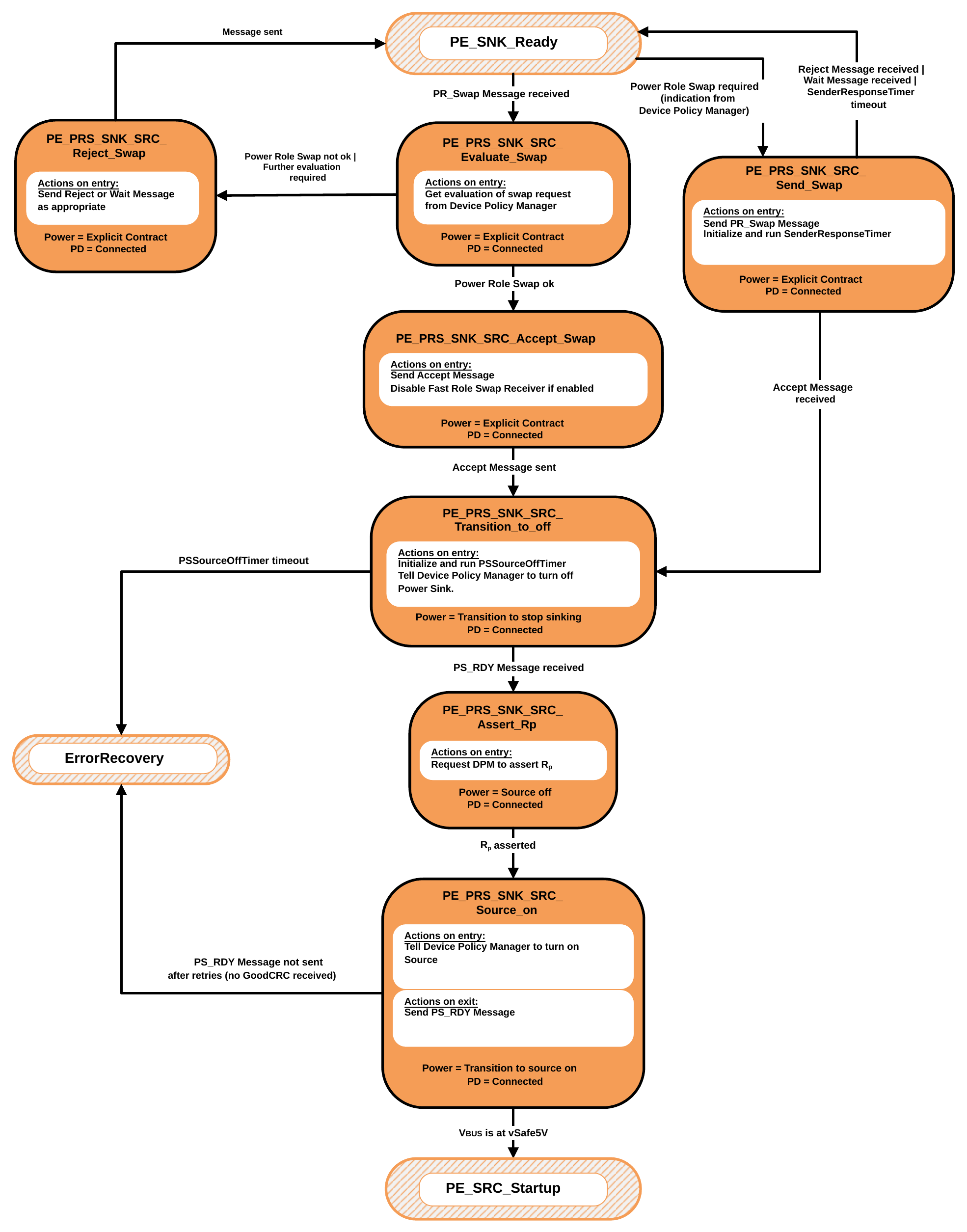
9.2.20.4.1. PE_SNK_Ready State
The Power Role Swap process Shall start only from the PE_SNK_Ready State where power is stable. The Policy Engine Shall transition to the PE_PRS_SNK_SRC_Evaluate_Swap State when:
- A PR_Swap Message is received.
The Policy Engine Shall transition to the PE_PRS_SNK_SRC_Send_Swap State when:
- The Device Policy Manager indicates that a Power Role Swap is required.
9.2.20.4.2. PE_PRS_SNK_SRC_Evaluate_Swap State
On entry to the PE_PRS_SNK_SRC_Send_Swap State the Policy Engine Shall ask the Device Policy Manager whether a Power Role Swap can be made.
The Policy Engine Shall transition to the PE_PRS_SNK_SRC_Accept_Swap State when:
- The Device Policy Manager indicates that a Power Role Swap is OK.
The Policy Engine Shall transition to the PE_PRS_SNK_SRC_Reject_Swap State when:
- The Device Policy Manager indicates that a Power Role Swap is not OK.
9.2.20.4.3. PE_PRS_SNK_SRC_Accept_Swap State
On entry to the PE_PRS_SNK_SRC_Accept_Swap State the Policy Engine Shall Request the Protocol Layer to send an
Accept Message and Shall disable the Fast Role Swap receiver if this is enabled.
The Policy Engine Shall transition to the PE_PRS_SNK_SRC_Transition_to_off State when:
- The Accept Message has been sent.
9.2.20.4.4. PE_PRS_SNK_SRC_Transition_to_off State
On entry to the PE_PRS_SNK_SRC_Transition_to_off State the Policy Engine Shall initialize and run the PSSourceOffTimer and then Request the Device Policy Manager to turn off the Sink. The Policy Engine Shall transition to the ErrorRecovery State when:
- The PSSourceOffTimer times out.
The Policy Engine Shall transition to the PE_PRS_SNK_SRC_Assert_Rp State when:
- A PS_RDY Message is received.
9.2.20.4.5. PE_PRS_SNK_SRC_Assert_Rp State
On entry to the PE_PRS_SNK_SRC_Assert_Rp State the Policy Engine Shall Request the Device Policy Manager to change the resistor asserted on the CC wire from Rd to Rp.
The Policy Engine Shall transition to the PE_PRS_SNK_SRC_Source_on State when:
- The Device Policy Manager indicates that Rd is asserted.
9.2.20.4.6. PE_PRS_SNK_SRC_Source_on State
On entry to the PE_PRS_SNK_SRC_Source_on State the Policy Engine Shall Request the Device Policy Manager to turn on the Source.
On exit from the PE_PRS_SNK_SRC_Source_on State the Policy Engine Shall send a PS_RDY Message. The Policy Engine Shall transition to the PE_SRC_Startup State when:
- The Source Port VBUS is at vSafe5V.
The Policy Engine Shall transition to the ErrorRecovery State when:
- The PS_RDY Message is not sent after retries (a GoodCRC Message has not been received). A Soft Reset
Shall Not be initiated in this case.
9.2.20.4.7. PE_PRS_SNK_SRC_Send_Swap State
On entry to the PE_PRS_SNK_SRC_Send_Swap State the Policy Engine Shall Request the Protocol Layer to send a PR_Swap Message and Shall initialize and run the SenderResponseTimer. The Policy Engine Shall transition to the PE_SNK_Ready State when:
-
A Reject Message is received.
-
Or a Wait Message is received.
-
Or the SenderResponseTimer times out.
The Policy Engine Shall transition to the PE_PRS_SNK_SRC_Transition_to_off State when:
- An Accept Message is received.
9.2.20.4.8. PE_PRS_SNK_SRC_Reject_Swap State
On entry to the PE_PRS_SNK_SRC_Reject_Swap State the Policy Engine Shall Request the Protocol Layer to send:
-
A Reject Message if the Device is unable to perform a Power Role Swap at this time.
-
A Wait Message if further evaluation of the Power Role Swap Request is required.
Note: In this case it is expected that one of the Port Partners will send a PR_Swap Message at a later time (see Section 7.10.1). The Policy Engine Shall transition to the PE_SNK_Ready State when:
- The Reject or Wait Message has been sent.
9.2.20.5. Policy Engine in Source to Sink Fast Role Swap State Diagram
Dual-Role Ports that combine Source and Sink functionality Shall comprise Source and Sink Policy Engine State machines. In addition, they Shall have the capability to do a Power Role Swap from the PE_SRC_Ready State and Shall return to USB Default Operation on a Hard Reset.
Figure 9.63 shows the additional State diagram required to perform a Power Role Swap from Source to Sink Power Roles and the changes that Shall be followed for error handling.
Figure 9.63. Dual-Role Port in Source to Sink Power Role Swap State Diagram
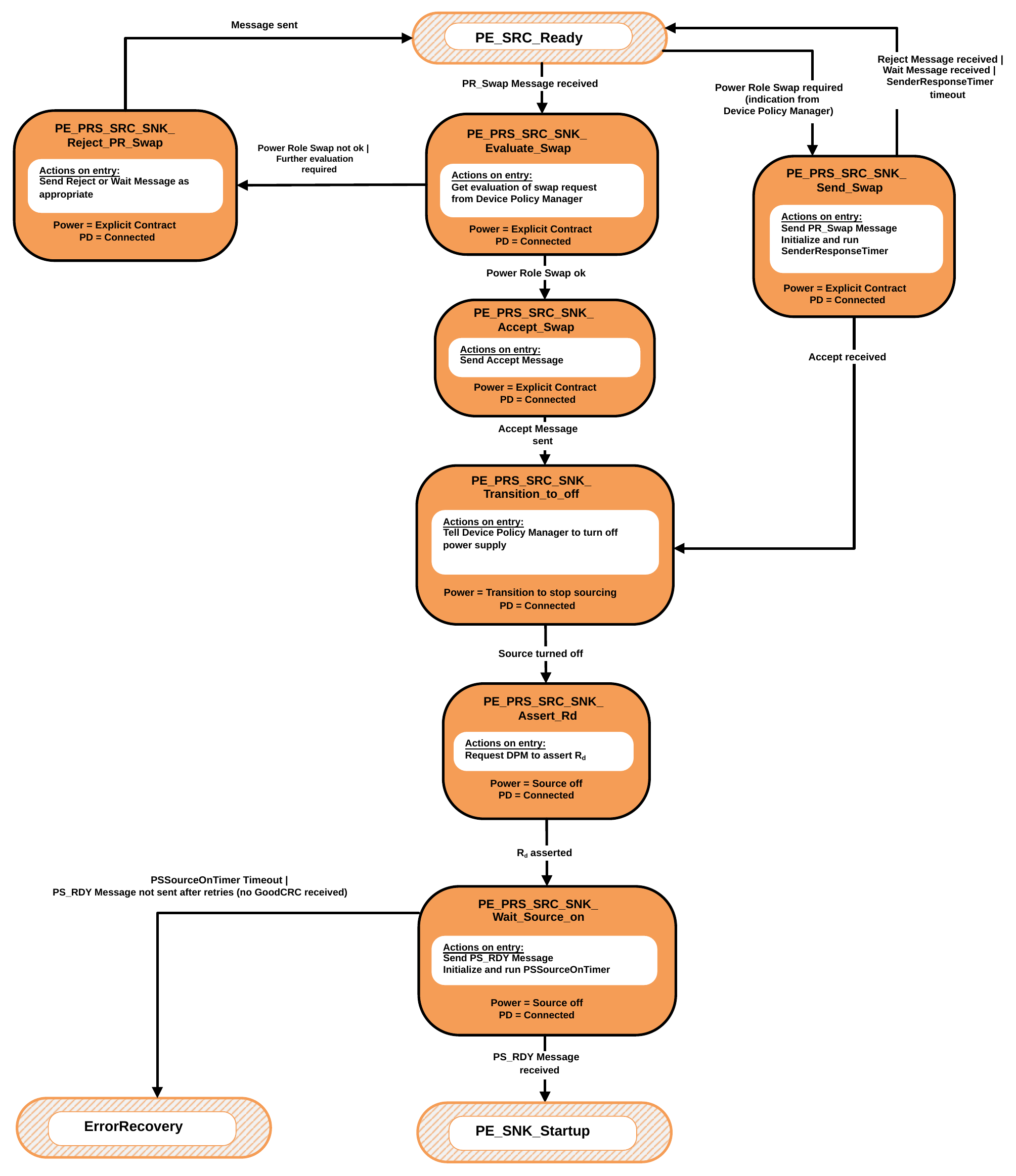
9.2.20.5.1. PE_SRC_Ready State
The Fast Role Swap process Shall start only from the PE_SRC_Ready State where power is stable. The Policy Engine Shall transition to the PE_FRS_SRC_SNK_Evaluate_Swap State when:
- An FR_Swap Message is received.
9.2.20.5.2. PE_FRS_SRC_SNK_Evaluate_Swap State
On entry to the PE_FRS_SRC_SNK_Evaluate_Swap State the Policy Engine Shall ask the Device Policy Manager whether Fast Role Swap has been signaled on the CC wire.
The Policy Engine Shall transition to the PE_FRS_SRC_SNK_Accept_Swap State when:
-
The Device Policy Manager indicates that a Fast Role Swap has been signaled. The Policy Engine Shall transition to the PE_SRC_Hard_Reset State when:
-
The Device Policy Manager indicates that a Fast Role Swap is not being signaled.
9.2.20.5.3. PE_FRS_SRC_SNK_Accept_Swap State
On entry to the PE_FRS_SRC_SNK_Accept_Swap State the Policy Engine Shall Request the Protocol Layer to send an Accept Message.
The Policy Engine Shall transition to the PE_FRS_SRC_SNK_Transition_to_off State when:
- The Accept Message has been sent.
The Policy Engine Shall transition to the PE_SRC_Hard_Reset State when:
- The Accept Message is not sent after retries (a GoodCRC Message has not been received).
Note: A Soft Reset Shall Not be initiated in this case.
9.2.20.5.4. PE_FRS_SRC_SNK_Transition_to_off State
On entry to the PE_FRS_SRC_SNK_Transition_to_off State the Policy Engine Shall wait until VBUS has discharged to vSafe5V.
The Policy Engine Shall transition to the PE_FRS_SRC_SNK_Assert_Rd State when:
- The Device Policy Manager indicates that VBUS has discharged to vSafe5V.
9.2.20.5.5. PE_FRS_SRC_SNK_Assert_Rd State
On entry to the PE_FRS_SRC_SNK_Assert_Rd State the Policy Engine Shall Request the Device Policy Manager to change the resistor asserted on the CC wire from Rp to Rd.
The Policy Engine Shall transition to the PE_FRS_SRC_SNK_Wait_Source_on State when:
- The Device Policy Manager indicates that Rd is asserted.
9.2.20.5.6. PE_FRS_SRC_SNK_Wait_Source_on State
-
A PS_RDY Message is received indicating that the New Source is now applying Rp. The Policy Engine Shall transition to the ErrorRecovery State when:
-
The PSSourceOnTimer times out or
-
The PS_RDY Message is not sent after retries (a GoodCRC Message has not been received).
Note: A Soft Reset Shall Not be initiated in this case.
9.2.20.6. Policy Engine in Sink to Source Fast Role Swap State Diagram
Dual-Role Ports that combine Sink and Source functionality Shall comprise Sink and Source Policy Engine State machines. In addition, they Should have the capability to do a Fast Role Swap from the PE_SNK_Ready State and Shall return to USB Default Operation on a Hard Reset.
Figure 9.64 shows the additional State diagram required to perform a Fast Role Swap from Sink to Source Power Roles and the changes that Shall be followed for error handling.
Figure 9.64. Dual-role Port in Sink to Source Fast Role Swap State Diagram
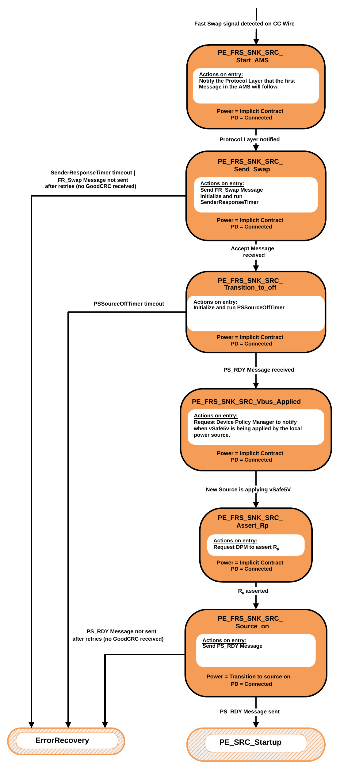
9.2.20.6.1. PE_FRS_SNK_SRC_Start_AMS State
The Policy Engine Shall transition to the PE_FRS_SNK_SRC_Start_AMS State from any other State provided there is an Explicit Contract in place when:
- The Sink Capabilities received from the Initial Source by the Policy Engine has at least one of the Fast Role Swap bits set.
- The system has sufficient reserve power to provide the requested current to the Initial Source, as requested in the Fast Role Swap bits in the Sink Capabilities, and is willing to dedicate it to the Port
- The Device Policy Manager indicates that a Fast Role Swap signal has been detected on the CC wire.
On entry to the PE_FRS_SNK_SRC_Start_AMS State the Policy Engine Shall notify the Protocol Layer that the first Message in an AMS will follow.
The Policy Engine Shall transition to the PE_FRS_SNK_SRC_Send_Swap State when:
- The Protocol Layer has been notified.
9.2.20.6.2. PE_FRS_SNK_SRC_Send_Swap State
On entry to the PE_FRS_SNK_SRC_Send_Swap State the Policy Engine Shall Request the Protocol Layer to send an FR_Swap Message and Shall initialize and run the SenderResponseTimer.
The Policy Engine Shall transition to the PE_FRS_SNK_SRC_Transition_to_off State when:
- An Accept Message is received.
The Policy Engine Shall transition to the ErrorRecovery State when:
- The SenderResponseTimer times out or
- The FR_Swap Message is not sent after retries (a GoodCRC Message has not been received). A Soft Reset Shall Not be initiated in this case.
9.2.20.6.3. PE_FRS_SNK_SRC_Transition_to_off State
On entry to the PE_FRS_SNK_SRC_Transition_to_off State the Policy Engine Shall initialize and run the PSSourceOffTimer and then Request the Device Policy Manager to turn off the Sink. The Policy Engine Shall transition to the ErrorRecovery State when:
- The PSSourceOffTimer times out.
The Policy Engine Shall transition to the PE_FRS_SNK_SRC_VBUS_Applied State when:
- A PS_RDY Message is received.
9.2.20.6.4. PE_FRS_SNK_SRC_VBUS_Applied State
On entry to the PE_FRS_SNK_SRC_VBUS_Applied State the Policy Engine waits for a notification from the Device Policy Manager that the local power Source has applied vSafe5V to VBUS (see Section 10.3).
Note: This could have already been applied prior to entering this State or could be applied while waiting in this State.
The Policy Engine Shall transition to the PE_FRS_SNK_SRC_Assert_Rp State when:
- The Device Policy Manager indicates that vSafe5V is being applied.
9.2.20.6.5. PE_FRS_SNK_SRC_Assert_Rp State
On entry to the PE_FRS_SNK_SRC_Assert_Rp State the Policy Engine Shall Request the Device Policy Manager to change the resistor asserted on the CC wire from Rd to Rp .
The Policy Engine Shall transition to the PE_FRS_SNK_SRC_Source_on State when:
- The Device Policy Manager indicates that Rp is asserted.
9.2.20.6.6. PE_FRS_SNK_SRC_Source_on State
On entry to the PE_FRS_SNK_SRC_Source_on State the Policy Engine Shall Request the Device Policy Manager to turn on the Source.
On exit from the PE_FRS_SNK_SRC_Source_on State the Policy Engine Shall send a PS_RDY Message. The Policy Engine Shall transition to the PE_SRC_Startup State when:
- The PS_RDY Message has been sent.
The Policy Engine Shall transition to the ErrorRecovery State when:
- The PS_RDY Message is not sent after retries (a GoodCRC Message has not been received). A Soft Reset Shall Not be initiated in this case.
9.2.20.7. Dual-Role (Source Port) Get Source Capabilities State Diagram
Figure 9.65 shows the State diagram for a Dual-Role Device, presently operating as a Source, on receiving a Request from the Device Policy Manager to get the Port Partner's Source Capabilities. See also Section 6.4.1.1.
Figure 9.65. Dual-Role (Source) Get Source Capabilities diagram

- Either SPR or EPR Source Capabilities May be requested, regardless of whether or not the Source is currently operating in SPR or EPR Mode..
9.2.20.7.1. PE_DR_SRC_Get_Source_Cap State
The Policy Engine Shall transition to the PE_DR_SRC_Get_Source_Cap State, from the PE_SRC_Ready State, due to a Request to get the remote Source Capabilities from the Device Policy Manager.
- On entry to the PE_DR_SRC_Get_Source_Cap State the Policy Engine Shall Request the Protocol Layer to send a get Source Capabilities Message in order to retrieve the Source Capabilities. The Policy Engine Shall send:
- A Get_Source_Cap Message when the Device Policy Manager requests SPR Capabilities or
- An EPR_Get_Source_Cap Message when the Device Policy Manager requests EPR Capabilities. The Policy Engine Shall then start the SenderResponseTimer.
On exit from the PE_DR_SRC_Get_Source_Cap State the Policy Engine Shall inform the Device Policy Manager of the outcome (Capabilities or response timeout).
The Policy Engine Shall transition back to the PE_SRC_Ready State (see Figure 9.17 ) when:
- In SPR Mode and SPR Source Capabilities were requested and a Source_Capabilities Message is received or
- In EPR Mode and EPR Source Capabilities were requested and an EPR_Source_Capabilities Message is received or
- The SenderResponseTimer times out.
9.2.20.8. Dual-Role (Source Port) Give Sink Capabilities State Diagram
Figure 9.66 shows the State diagram for a Dual-Role Device, presently operating as a Source, on receiving a Get_Sink_Cap Message. See also Section 6.3.8.
Figure 9.66. Dual-Role (Source) Give Sink Capabilities diagram
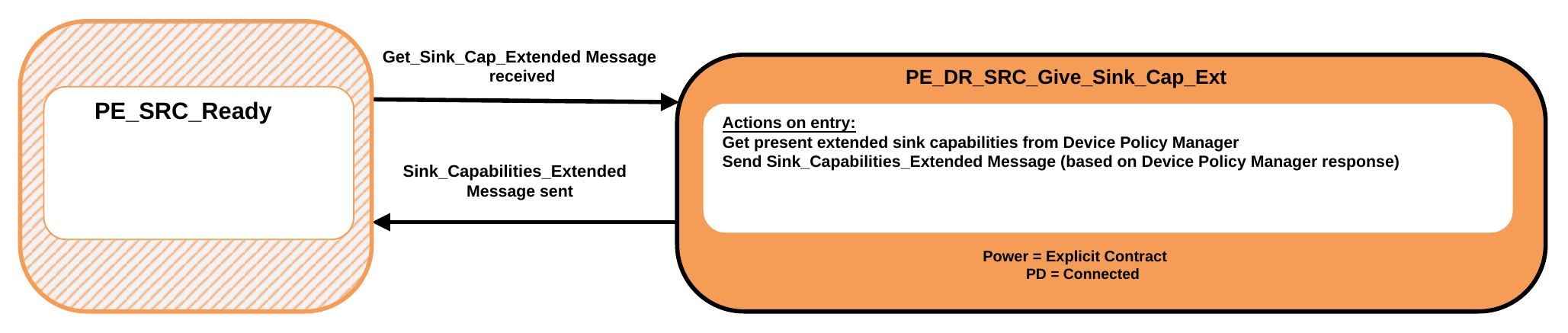
9.2.20.8.1. PE_DR_SRC_Give_Sink_Cap State
The Policy Engine Shall transition to the PE_DR_SRC_Give_Sink_Cap State, from the PE_SRC_Ready State, when a Get_Sink_Cap Message or EPR_Get_Sink_Cap Message is received.
- On entry to the PE_DR_SRC_Give_Sink_Cap State the Policy Engine Shall Request the Device Policy Manager for the current system Capabilities. The Policy Engine Shall then Request the Protocol Layer to send a Sink_Capabilities Message containing these Capabilities. The Policy Engine Shall send:
- A Sink_Capabilities Message when a Get_Sink_Cap Message is received or
- An EPR_Sink_Capabilities Message when a EPR_Get_Sink_Cap Message is received.
The Policy Engine Shall transition back to the PE_SRC_Ready State (see Figure 9.17 ) when:
- The Sink_Capabilities Message has been successfully sent.
9.2.20.9. Dual-Role (Sink Port) Get Sink Capabilities State Diagram
Figure 9.67 shows the State diagram for a Dual-Role Device, presently operating as a Sink, on receiving a Request from the Device Policy Manager to get the Port Partner's Sink Capabilities. See also Section 6.4.1.2.
Figure 9.67. Dual-Role (Sink) Get Sink Capabilities State Diagram
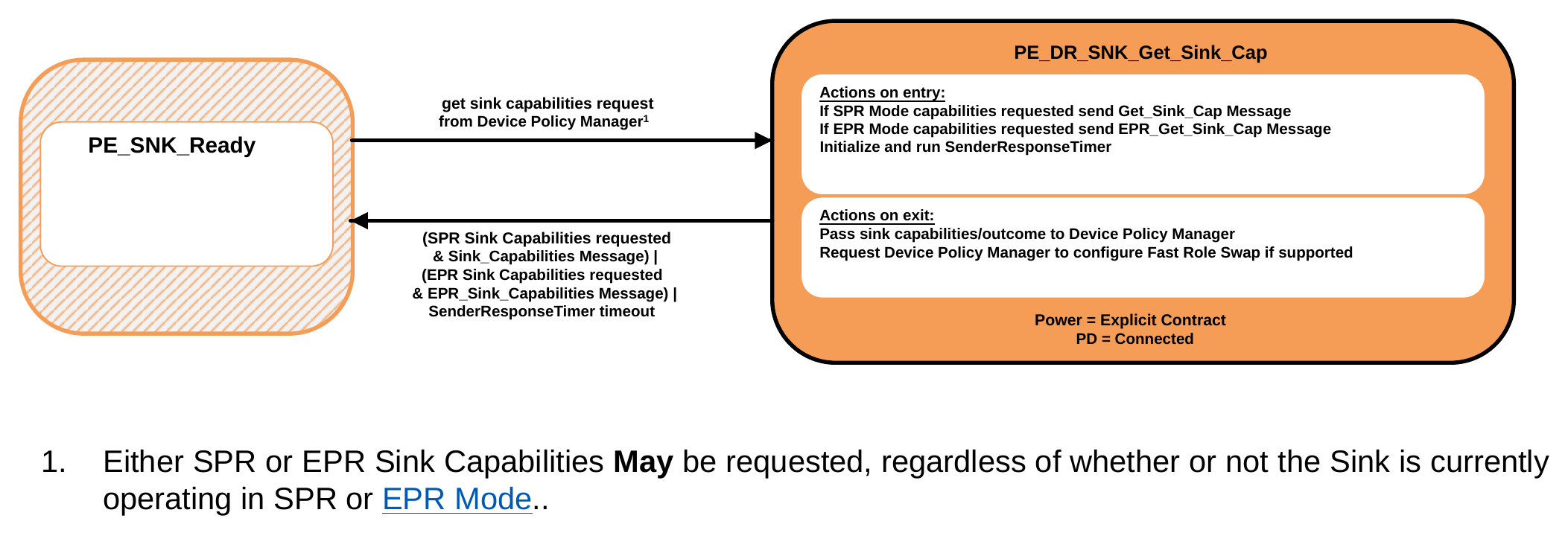
- Either SPR or EPR Sink Capabilities May be requested, regardless of whether or not the Sink is currently operating in SPR or EPR Mode..
9.2.20.9.1. PE_DR_SNK_Get_Sink_Cap State
The Policy Engine Shall transition to the PE_DR_SNK_Get_Sink_Cap State, from the PE_SNK_Ready State, due to a Request to get the remote Source Capabilities from the Device Policy Manager.
- On entry to the PE_DR_SNK_Get_Sink_Cap State the Policy Engine Shall Request the Protocol Layer to send a Get_Sink_Cap Message in order to retrieve the Sink Capabilities. The Policy Engine Shall send:
- A Get_Sink_Cap Message when the Device Policy Manager requests SPR Capabilities or
- An EPR_Get_Sink_Cap Message when the Device Policy Manager requests EPR Capabilities. The Policy Engine Shall then start the SenderResponseTimer.
On exit from the PE_SRC_Get_Sink_Cap State the Policy Engine Shall inform the Device Policy Manager of the outcome (Capabilities or response timeout). If Fast Role Swap is supported, Request Device Policy Manager prepare or disable 5V Source and configure the Fast Role Swap receiver based on the Fast Role Swap required USB Type- C Current bits in the received Sink Capabilities.
The Policy Engine Shall transition to the PE_SNK_Ready State (see Figure 9.18 ) when:
- SPR Sink Capabilities were requested and a Sink_Capabilities Message is received or
- EPR Sink Capabilities were requested and an EPR_Sink_Capabilities Message is received or
- The SenderResponseTimer times out.
9.2.20.10. Dual-Role (Sink Port) Give Source Capabilities State Diagram
Figure 9.68 shows the State diagram for a Dual-Role Device, presently operating as a Sink, on receiving a Get_Source_Cap Message. See also Section 6.3.7.
Figure 9.68. Dual-Role (Sink) Give Source Capabilities State Diagram
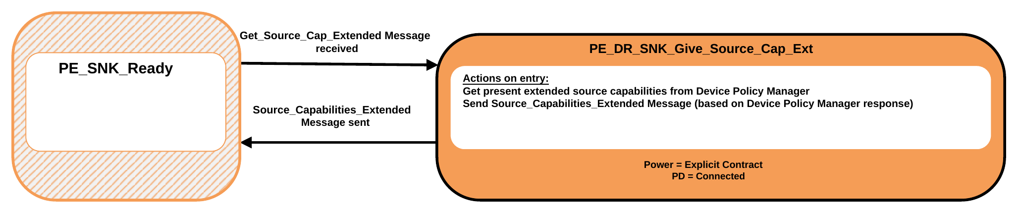
9.2.20.10.1. PE_DR_SNK_Give_Source_Cap State
The Policy Engine Shall transition to the PE_DR_SNK_Give_Source_Cap State, from the PE_SNK_Ready State, when a Get_Source_Cap Message is received.
- On entry to the PE_DR_SNK_Give_Source_Cap State the Policy Engine Shall Request the Device Policy Manager for the current system Capabilities. The Policy Engine Shall then Request the Protocol Layer to send a Source Capabilities Message containing these Capabilities.
- The Policy Engine Shall send:
- A Source_Capabilities Message when a Get_Source_Cap Message is received or
- An EPR_Source_Capabilities Message when a EPR_Get_Source_Cap Message is received.
The Policy Engine Shall transition to the PE_SNK_Ready State (see Figure 9.18 ) when:
- The Source Capabilities Message has been successfully sent.
9.2.20.11. Dual-Role (Source Port) Get Source Capabilities Extended State Diagram
Figure 9.69 shows the State diagram for Dual-Role Device, presently operating as a Source, on receiving a Request from the Device Policy Manager to get the Port Partner's extended Source Capabilities. See also Section 6.5.2.
Figure 9.69. Dual-Role (Source) Get Source Capabilities Extended State Diagram
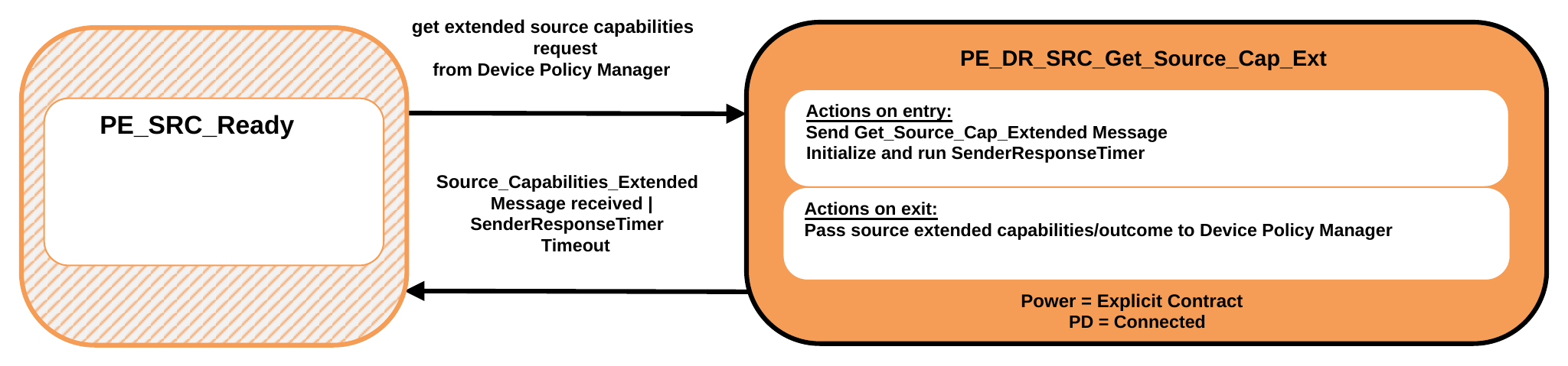
9.2.20.11.1. PE_DR_SRC_Get_Source_Cap_Ext State
The Policy Engine Shall transition to the PE_DR_SRC_Get_Source_Cap_Ext State, from the PE_SRC_Ready State, due to a Request to get the remote extended Source Capabilities from the Device Policy Manager.
On entry to the PE_DR_SRC_Get_Source_Cap_Ext State the Policy Engine Shall send a Get_Source_Cap_Extended Message and initialize and run the SenderResponseTimer.
On exit from the PE_DR_SRC_Get_Source_Cap_Ext State the Policy Engine Shall inform the Device Policy Manager of the outcome (Capabilities or response timeout).
The Policy Engine Shall transition back to the PE_SRC_Ready State (see Figure 9.17 ) when:
- A Source_Capabilities_Extended Message is received
- Or SenderResponseTimer times out.
9.2.20.12. Dual-Role (Sink Port) Give Source Capabilities Extended State Diagram
Figure 9.68 shows the State diagram for a Dual-Role Device, presently operating as a Sink, on receiving a Get_Source_Cap_Extended Message. See also Section 7.19.2.
Figure 9.70. Dual-Role (Sink) Give Source Capabilities Extended diagram
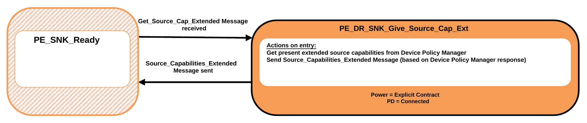
9.2.20.12.1. PE_DR_SNK_Give_Source_Cap_Ext State
The Policy Engine Shall transition to the PE_DR_SNK_Give_Source_Cap_Ext State, from the PE_SNK_Ready State, when a Get_Source_Cap_Extended Message is received.
On entry to the PE_DR_SNK_Give_Source_Cap_Ext State the Policy Engine Shall Request the present extended Source Capabilities from the Device Policy Manager and then send a Source_Capabilities_Extended Message based on these Capabilities.
The Policy Engine Shall transition back to the PE_SNK_Ready State (see Figure 9.18 ) when:
- The Source_Capabilities_Extended Message has been successfully sent.
9.2.20.13. Dual-Role (Sink Port) Get Sink Capabilities Extended State Diagram
Figure 9.67 shows the State diagram for a Dual-Role Device, presently operating as a Sink, on receiving a Request from the Device Policy Manager to get the Port Partner's extended Sink Capabilities. See also Section 6.5.16.
Figure 9.71. Dual-Role (Sink) Get Sink Capabilities Extended State Diagram
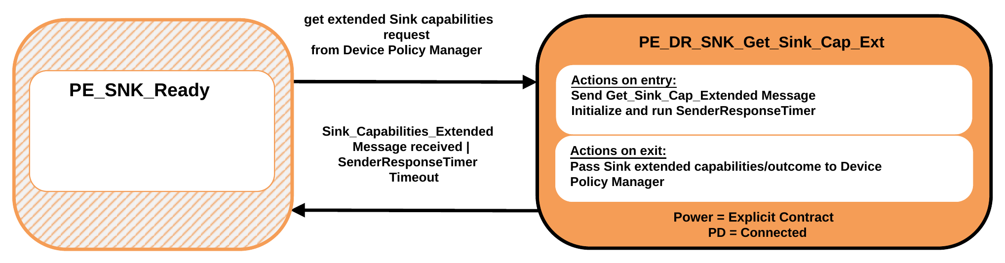
9.2.20.13.1. PE_DR_SNK_Get_Sink_Cap_Ext State
The Policy Engine Shall transition to the PE_DR_SNK_Get_Sink_Cap_Ext State, from the PE_SNK_Ready State, due to a Request to get the remote extended Source Capabilities from the Device Policy Manager.
On entry to the PE_DR_SNK_Get_Sink_Cap_Ext State the Policy Engine Shall send a Get_Sink_Cap_Extended Message and initialize and run the SenderResponseTimer.
On exit from the PE_DR_SNK_Get_Sink_Cap_Ext State the Policy Engine Shall inform the Device Policy Manager of the outcome (Capabilities or response timeout).
The Policy Engine Shall transition back to the PE_SNK_Ready State (see Figure 9.18 ) when:
-
A Sink_Capabilities_Extended Message is received.
-
Or SenderResponseTimer times out.
9.2.20.14. Dual-Role (Source Port) Give Sink Capabilities Extended State Diagram
Figure 9.72 shows the State diagram for a Dual-Role Device, presently operating as a Sink, on receiving a Get_Sink_Cap_Extended Message. See also Section 6.5.16.
Figure 9.72. Dual-Role (Source) Give Sink Capabilities Extended diagram
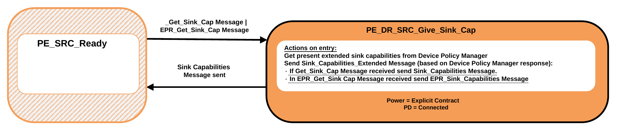
9.2.20.14.1. PE_DR_SRC_Give_Sink_Cap_Ext State
The Policy Engine Shall transition to the PE_DR_SRC_Give_Sink_Cap_Ext State, from the PE_SRC_Ready State, when a Get_Sink_Cap_Extended Message is received.
On entry to the PE_DR_SRC_Give_Sink_Cap_Ext State the Policy Engine Shall Request the present extended Sink Capabilities from the Device Policy Manager and then send a Sink_Capabilities_Extended Message based on these Capabilities.
The Policy Engine Shall transition back to the PE_SRC_Ready State (see Figure 9.17 )when:
- The Sink_Capabilities_Extended Message has been successfully sent.
9.2.20.15. Dual-Role (Source Port) Get Source Information State Diagram
Figure 9.73 shows the State diagram for a Dual-Role Device, presently operating as a Source, on receiving a Request from the Device Policy Manager to get the Port Partner's Source information. See also Section 6.3.23 and Section 6.4.10.
Figure 9.73. Dual-Role (Source) Get Source Information State Diagram
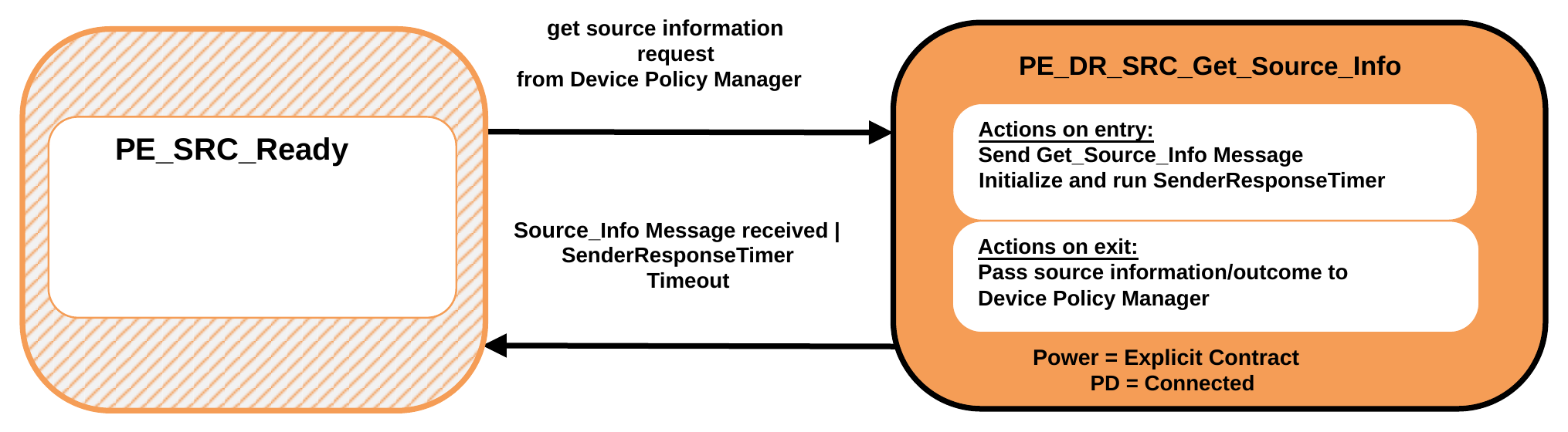
9.2.20.15.1. PE_DR_SRC_Get_Source_Info State
The Policy Engine Shall transition to the PE_DR_SRC_Get_Source_Info State, from the PE_SRC_Ready State, due to a Request to get the remote Source information from the Device Policy Manager.
On entry to the PE_DR_SRC_Get_Source_Info State the Policy Engine Shall send a Get_Source_Info Message and initialize and run the SenderResponseTimer.
On exit from the PE_DR_SRC_Get_Source_Info State the Policy Engine Shall inform the Device Policy Manager of the outcome (information or response timeout).
The Policy Engine Shall transition back to the PE_SRC_Ready State (see Figure 9.17 ) when:
-
A Source_Info Message is received.
-
Or SenderResponseTimer times out.
9.2.20.16. Dual-Role (Sink Port) Give Source Information State Diagram
Figure 9.68 shows the State diagram for a Dual-Role Device, presently operating as a Sink, on receiving a Get_Source_Info Message. See also Section 6.3.23 and Section 6.4.10.
Figure 9.74. Dual-Role (Source) Give Source Information diagram
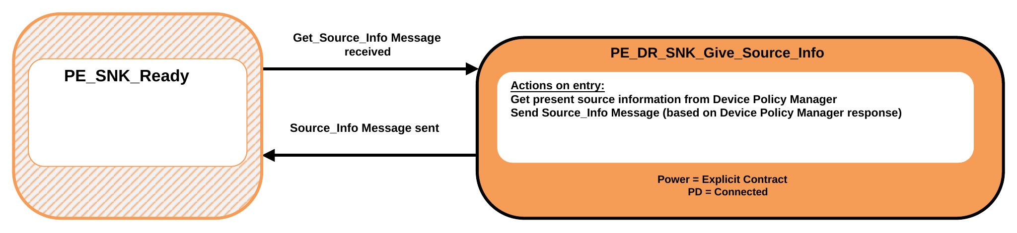
9.2.20.16.1. PE_DR_SNK_Give_Source_Info State
The Policy Engine Shall transition to the PE_DR_SNK_Give_Source_Info State, from the PE_SNK_Ready State, when a Get_Source_Info Message is received.
On entry to the PE_DR_SNK_Give_Source_Info State the Policy Engine Shall Request the present Source information from the Device Policy Manager and then send a Source_Info Message based on this information.
The Policy Engine Shall transition back to the PE_SNK_Ready State (see Figure 9.18 ) when:
- The Source_Info Message has been successfully sent.
9.2.21. VCONN Swap State Diagram
The State Diagram in this section Shall apply to Ports that supply VCONN. Figure 9.75 shows the State operation for a Port on sending or receiving a VCONN Swap Request.
Figure 9.75. VCONN Swap State Diagram
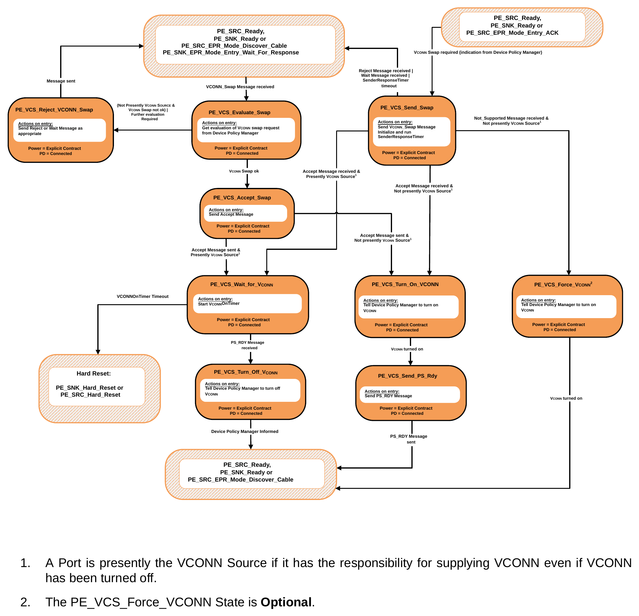
-
A Port is presently the VCONN Source if it has the responsibility for supplying VCONN even if VCONN has been turned off.
-
The PE_VCS_Force_VCONN State is Optional.
9.2.21.1. PE_VCS_Send_Swap State
The PE_VCS_Send_Swap State is entered from either the PE_SRC_Ready or PE_SNK_Ready State when the Policy Engine receives a Request from the Device Policy Manager to perform a VCONN Swap.
On entry to the PE_VCS_Send_Swap State the Policy Engine Shall send a VCONN_Swap Message and start the SenderResponseTimer.
The Policy Engine Shall transition to the PE_VCS_Wait_For_VCONN State when:
-
An Accept Message is received and
-
The Port is presently the VCONN Source.
The Policy Engine Shall transition to the PE_VCS_Turn_On_VCONN State when:
-
An Accept Message is received and
-
The Port is not presently the VCONN Source.
The Policy Engine Shall transition back to either the PE_SRC_Ready, PE_SNK_Ready or PE_SRC_EPR_Mode_Discover_Cable State when:
-
A Reject Message is received or
-
A Wait Message is received or
-
The SenderResponseTimer times out.
The Policy Engine May transition to the PE_VCS_Force_VCONN State when:
-
A Not_Supported Message is received and
-
The Port is not presently the VCONN Source.
9.2.21.2. PE_VCS_Evaluate_Swap State
The PE_VCS_Evaluate_Swap State is entered from either the PE_SRC_Ready or PE_SNK_Ready State when the Policy Engine receives a VCONN_Swap Message.
On entry to the PE_VCS_Evaluate_Swap State the Policy Engine Shall Request the Device Policy Manager for an evaluation of the VCONN Swap Request.
The Policy Engine Shall transition to the PE_VCS_Accept_Swap State when:
- The Device Policy Manager indicates that a VCONN Swap is OK.
The Policy Engine Shall transition to the PE_VCS_Reject_Swap State when:
-
The Port is not presently the VCONN Source and the Device Policy Manager indicates that a VCONN Swap is not OK or
-
The Device Policy Manager indicates that a VCONN Swap cannot be done at this time.
9.2.21.3. PE_VCS_Accept_Swap State
On entry to the PE_VCS_Accept_Swap State the Policy Engine Shall send an Accept Message. The Policy Engine Shall transition to the PE_VCS_Wait_For_VCONN State when:
-
The Accept Message has been sent and
-
The Port's VCONN is on.
The Policy Engine Shall transition to the PE_VCS_Turn_On_VCONN State when:
-
The Accept Message has been sent and
-
The Port's VCONN is off.
9.2.21.4. PE_VCS_Reject_Swap State
On entry to the PE_VCS_Reject_Swap State the Policy Engine Shall Request the Protocol Layer to send:
-
A Reject Message if the Device is unable to perform a VCONN Swap at this time.
-
A Wait Message if further evaluation of the VCONN Swap Request is required.
Note: In this case it is expected that the Port will send a VCONN_Swap Message at a later time. The Policy Engine Shall transition back to either the PE_SRC_Ready, PE_SNK_Ready or PE_SRC_EPR_Mode_Discover_Cable State when:
- The Reject or Wait Message has been sent.
9.2.21.5. PE_VCS_Wait_for_VCONN State
On entry to the PE_VCS_Wait_For_VCONN State the Policy Engine Shall start the VconnOnTimer. The Policy Engine Shall transition to the PE_VCS_Turn_Off_VCONN State when:
- A PS_RDY Message is received.
The Policy Engine Shall transition to either the PE_SRC_Hard_Reset or PE_SNK_Hard_Reset State when:
- The VconnOnTimer times out.
9.2.21.6. PE_VCS_Turn_Off_VCONN State
On entry to the PE_VCS_Turn_Off_VCONN State the Policy Engine Shall tell the Device Policy Manager to turn off VCONN.
The Policy Engine Shall transition back to either the PE_SRC_Ready, PE_SNK_Ready or PE_SRC_EPR_Mode_Discover_Cable State when:
- The Device Policy Manager has been informed.
9.2.21.7. PE_VCS_Turn_On_VCONN State
On entry to the PE_VCS_Turn_On_VCONN State the Policy Engine Shall tell the Device Policy Manager to turn on VCONN.
The Policy Engine Shall transition to the PE_VCS_Send_Ps_Rdy State when:
- The Port's VCONN is on.
9.2.21.8. PE_VCS_Send_PS_Rdy State
On entry to the PE_VCS_Send_Ps_Rdy State the Policy Engine Shall send a PS_RDY Message. The Policy Engine Shall transition back to either the PE_SRC_Ready, PE_SNK_Ready or PE_SRC_EPR_Mode_Discover_Cable State when:
- The PS_RDY Message has been sent.
9.2.21.9. PE_VCS_Force_VCONN State
On entry to the PE_VCS_Force_VCONN State the Policy Engine Shall tell the Device Policy Manager to turn on VCONN. The Policy Engine Shall transition back to either the PE_SRC_Ready, PE_SNK_Ready or PE_SRC_EPR_Mode_Discover_Cable State when:
- The Port's VCONN is on.
9.2.22. Initiator Structured VDM State Diagrams
The State Diagrams in this section Shall apply to all Initiators.
9.2.22.1. Initiator Structured VDM Discover Identity State Diagram
Figure 9.76 shows the State diagram for an Initiator when discovering the identity of its Port Partner or Cable Plug.
Figure 9.76. Initiator to Port VDM Discover Identity State Diagram
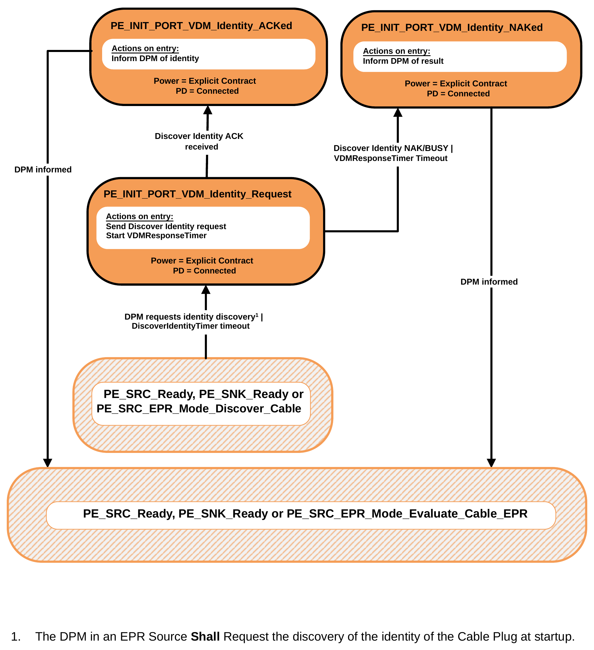
- The DPM in an EPR Source Shall Request the discovery of the identity of the Cable Plug at startup.
9.2.22.1.1. PE_INIT_Port_VDM_Identity_Request State
The Policy Engine transitions to the PE_INIT_Port_VDM_Identity_Request State from either the PE_SRC_Ready or PE_SNK_Ready State when:
-
The Device Policy Manager requests the discovery of the identity of the Port Partner or Cable Plug or
-
The DiscoverIdentityTimer times out.
The Policy Engine transitions to the PE_INIT_Port_VDM_Identity_Request State from the PE_SRC_EPR_Mode_Discover_Cable State when:
- The Cable Plug Discovery Process has been initiated.
On entry to the PE_INIT_Port_VDM_Identity_Request State the Policy Engine Shall send a Structured VDM Discover Identity Command Request and Shall start the VDMResponseTimer.
The Policy Engine Shall transition to the PE_INIT_Port_VDM_Identity_ACKed State when:
- A Structured VDM Discover Identity ACK Command response is received.
The Policy Engine Shall transition to the PE_INIT_Port_VDM_Identity_NAKed State when:
-
A Structured VDM Discover Identity NAK or BUSY Command response is received or
-
The VDMResponseTimer times out.
9.2.22.1.2. PE_INIT_Port_VDM_Identity_ACKed State
On entry to the PE_INIT_Port_VDM_Identity_ACKed State the Policy Engine Shall inform the Device Policy Manager of the Identity information.
The Policy Engine Shall transition to either the PE_SRC_Ready, PE_SNK_Ready or PE_SRC_EPR_Mode_Evaluate_Cable_EPR State when:
- The Device Policy Manager has been informed.
9.2.22.1.3. PE_INIT_Port_VDM_Identity_NAKed State
On entry to the PE_INIT_Port_VDM_Identity_NAKed State the Policy Engine Shall inform the Device Policy Manager of the result (NAK, BUSY or timeout).
The Policy Engine Shall transition to either the PE_SRC_Ready, PE_SNK_Ready or PE_SRC_EPR_Mode_Evaluate_Cable_EPR State when:
- The Device Policy Manager has been informed.
9.2.22.2. Initiator Structured VDM Discover SVIDs State Diagram
Figure 9.77 shows the State diagram for an Initiator when discovering SVIDs of its Port Partner or Cable Plug.
Figure 9.77. Initiator VDM Discover SVIDs State Diagram
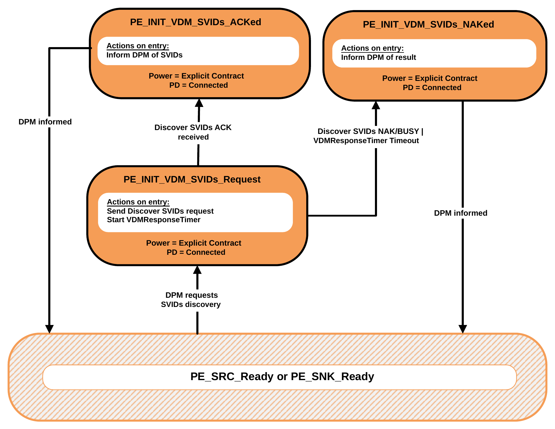
9.2.22.2.1. PE_INIT_VDM_SVIDs_Request State
The Policy Engine transitions to the PE_INIT_VDM_SVIDs_Request State from either the PE_SRC_Ready or PE_SNK_Ready State when:
- The Device Policy Manager requests the discovery of the SVIDs of the Port Partner or a Cable Plug.
On entry to the PE_INIT_VDM_SVIDs_Request State the Policy Engine Shall send a Structured VDM Discover SVIDs Command Request and Shall start the VDMResponseTimer.
The Policy Engine Shall transition to the PE_INIT_VDM_SVIDs_ACKed State when:
- A Structured VDM Discover SVIDs ACK Command response is received. The Policy Engine Shall transition to the PE_INIT_VDM_SVIDs_NAKed State when:
- A Structured VDM Discover SVIDs NAK or BUSY Command response is received or
- The VDMResponseTimer times out.
9.2.22.2.2. PE_INIT_VDM_SVIDs_ACKed State
On entry to the PE_INIT_VDM_SVIDs_ACKed State the Policy Engine Shall inform the Device Policy Manager of the SVIDs information.
The Policy Engine Shall transition to either the PE_SRC_Ready or PE_SNK_Ready State when:
- The Device Policy Manager has been informed.
9.2.22.2.3. PE_INIT_VDM_SVIDs_NAKed State
On entry to the PE_INIT_VDM_SVIDs_NAKed State the Policy Engine Shall inform the Device Policy Manager of the result (NAK, BUSY or timeout).
The Policy Engine Shall transition to either the PE_SRC_Ready or PE_SNK_Ready State when:
- The Device Policy Manager has been informed.
9.2.22.3. Initiator Structured VDM Discover Modes State Diagram
Figure 9.78 shows the State diagram for an Initiator when discovering Modes of its Port Partner or Cable Plug.
Figure 9.78. Initiator VDM Discover Modes State Diagram
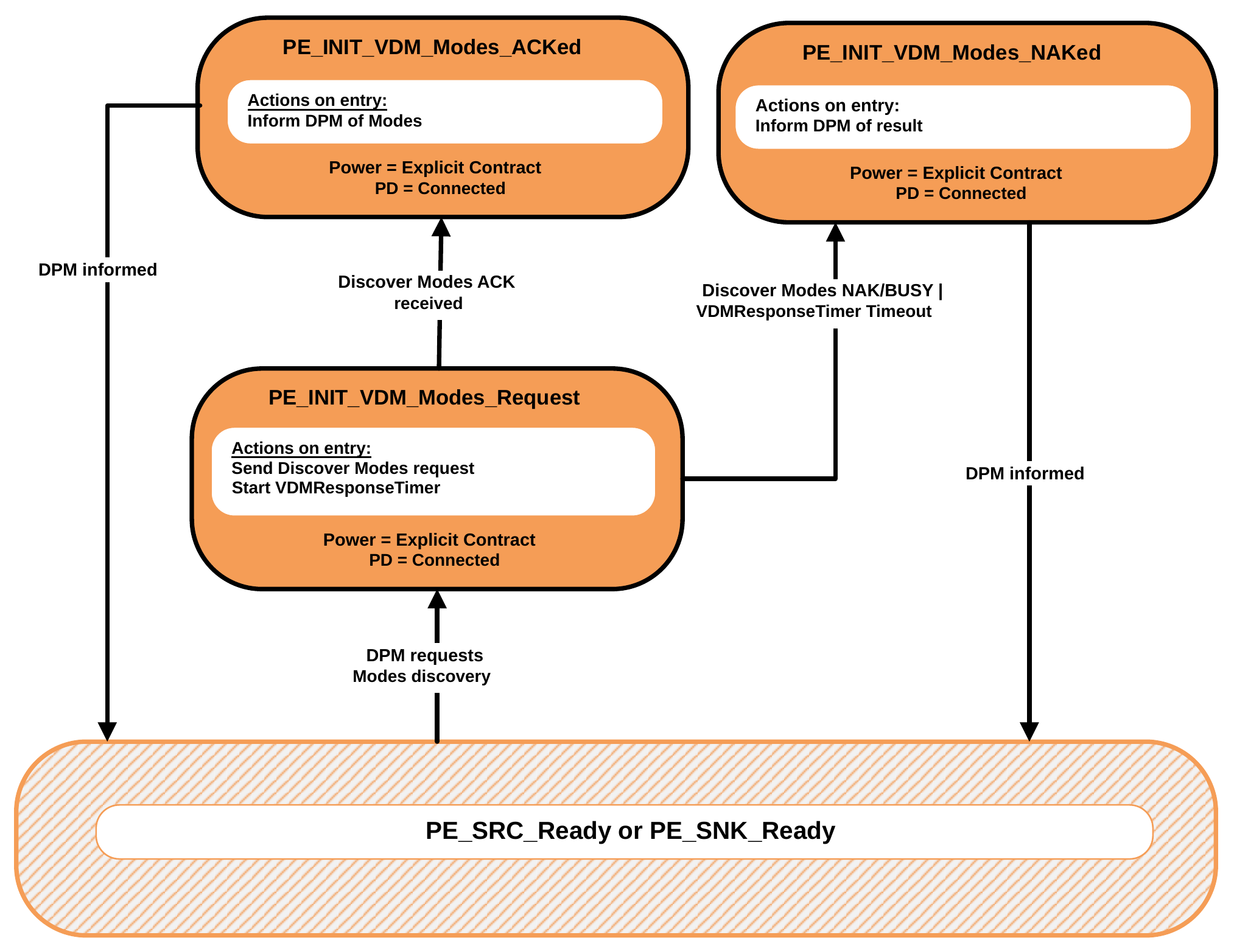
9.2.22.4. Initiator Structured VDM Attention State Diagram
Figure 9.79 shows the State diagram for an Initiator when sending an Attention Command Request.
Figure 9.79. Initiator VDM Attention State Diagram
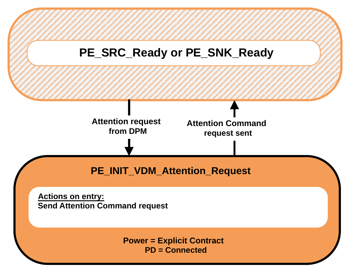
9.2.22.4.1. PE_INIT_VDM_Modes_Request State
The Policy Engine transitions to the PE_INIT_VDM_Modes_Request State from either the PE_SRC_Ready or PE_SNK_Ready State when:
- The Device Policy Manager requests the discovery of the Modes of the Port Partner or a Cable Plug.
On entry to the PE_INIT_VDM_Modes_Request State the Policy Engine Shall send a Structured VDM Discover Modes Command Request and Shall start the VDMResponseTimer.
The Policy Engine Shall transition to the PE_INIT_VDM_Modes_ACKed State when:
- A Structured VDM Discover Modes ACK Command response is received. The Policy Engine Shall transition to the PE_INIT_VDM_Modes_NAKed State when:
- A Structured VDM Discover Modes NAK or BUSY Command response is received or
- The VDMResponseTimer times out.
9.2.22.4.2. PE_INIT_VDM_Modes_ACKed State
On entry to the PE_INIT_VDM_Modes_ACKed State the Policy Engine Shall inform the Device Policy Manager of the Modes information.
The Policy Engine Shall transition to either the PE_SRC_Ready or PE_SNK_Ready State for a DFP when:
- The Device Policy Manager has been informed.
9.2.22.4.3. PE_INIT_VDM_Modes_NAKed State
On entry to the PE_INIT_VDM_Modes_NAKed State the Policy Engine Shall inform the Device Policy Manager of the result (NAK, BUSY or timeout).
The Policy Engine Shall transition to either the PE_SRC_Ready or PE_SNK_Ready State for a DFP when:
- The Device Policy Manager has been informed.
9.2.22.4.4. PE_INIT_VDM_Attention_Request State
The Policy Engine transitions to the PE_INIT_VDM_Attention_Request State from either the PE_SRC_Ready or PE_SNK_Ready State when:
- When the Device Policy Manager requests attention from its Port Partner.
On entry to the PE_INIT_VDM_Attention_Request State the Policy Engine Shall send an Attention Command Request.
The Policy Engine Shall transition to either the PE_SRC_Ready or PE_SNK_Ready State when:
- The Attention Command Request has been sent.
9.2.23. Responder Structured VDM State Diagrams
9.2.23.1. Responder Structured VDM Discover Identity State Diagram
Figure 9.80 shows the State diagram for a Responder receiving a Discover Identity Command Request.
Figure 9.80. Responder Structured VDM Discover Identity State Diagram
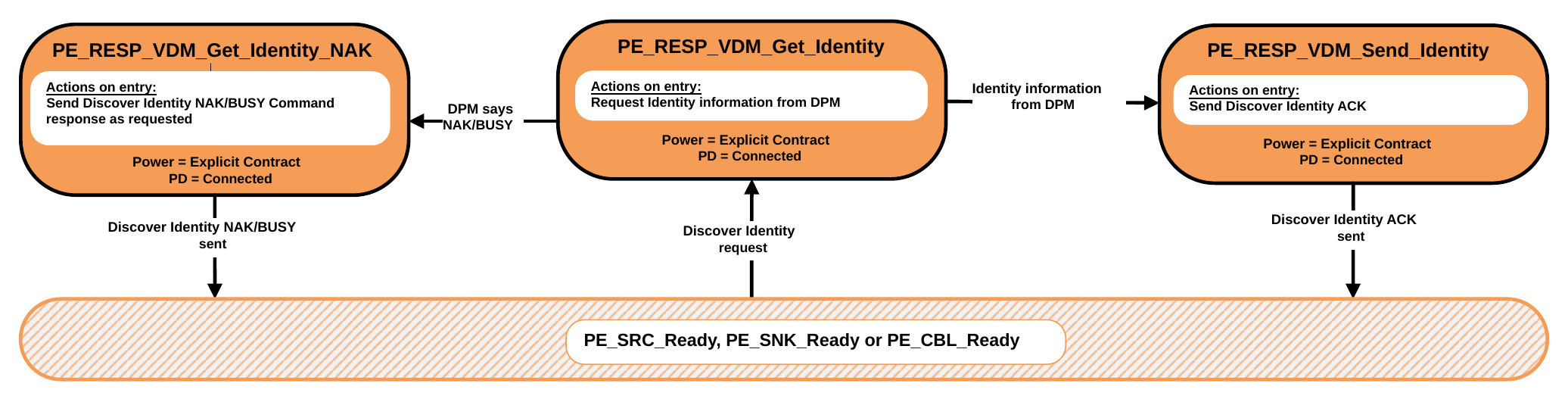
The Policy Engine transitions to the PE_RESP_VDM_Get_Identity State from either the PE_SRC_Ready, PE_SNK_Ready or PE_CBL_Ready State when:
- A Structured VDM Discover Identity Command Request is received.
On entry to the PE_RESP_VDM_Get_Identity State the Responder Shall Request identity information from the Device Policy Manager.
The Policy Engine Shall transition to the PE_RESP_VDM_Send_Identity State when:
- Identity information is received from the Device Policy Manager.
The Policy Engine Shall transition to the PE_RESP_VDM_Get_Identity_NAK State when:
- The Device Policy Manager indicates that the response to the Discover Identity Command Request isNAK or BUSY.
9.2.23.1.1. PE_RESP_VDM_Send_Identity State
On entry to the PE_RESP_VDM_Send_Identity State the Responder Shall send the Structured VDM Discover Identity ACK Command response.
The Policy Engine Shall transition to either the PE_SRC_Ready or PE_SNK_Ready State for a UFP when:
- The Structured VDM Discover Identity ACK Command response has been sent.
9.2.23.1.2. PE_RESP_VDM_Get_Identity_NAK State
On entry to the PE_RESP_VDM_Get_Identity_NAK State the Policy Engine Shall send a Structured VDM Discover Identity NAK or BUSY Command response as indicated by the Device Policy Manager.
The Policy Engine Shall transition to either the PE_SRC_Ready, PE_SNK_Ready or PE_CBL_Ready State when:
- The Structured VDM Discover Identity NAK or BUSY Command response has been sent.
9.2.23.2. Responder Structured VDM Discover SVIDs State Diagram
Figure 9.81 shows the State diagram for a Responder when receiving a Discover SVIDs Command.
Figure 9.81. Responder Structured VDM Discover SVIDs State Diagram
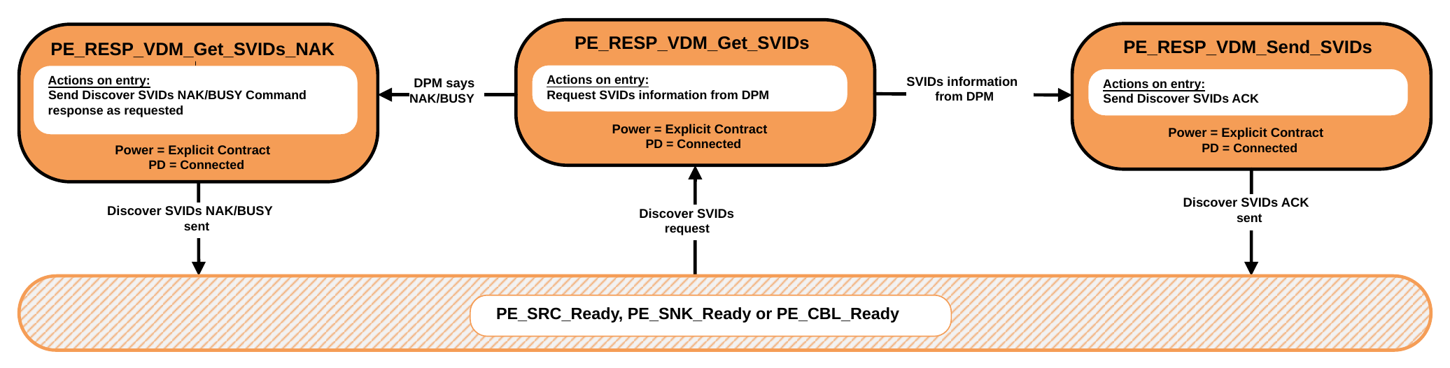
The Policy Engine transitions to the PE_RESP_VDM_Get_SVIDs State from either the PE_SRC_Ready, PE_SNK_Ready or PE_CBL_Ready State when:
- A Structured VDM Discover SVIDs Command Request is received.
On entry to the PE_RESP_VDM_Get_SVIDs State the Responder Shall Request SVIDs information from the Device Policy Manager.
The Policy Engine Shall transition to the PE_RESP_VDM_Send_SVIDs State when:
- SVIDs information is received from the Device Policy Manager.
The Policy Engine Shall transition to the PE_RESP_VDM_Get_SVIDs_NAK State when:
- The Device Policy Manager indicates that the response to the Discover SVIDs Command Request is NAK or BUSY.
9.2.23.2.1. PE_UFP_VDM_Send_SVIDs State
On entry to the PE_RESP_VDM_Send_SVIDs State the Responder Shall send the Structured VDM Discover SVIDs ACK Command response.
The Policy Engine Shall transition to either the PE_SRC_Ready, PE_SNK_Ready or PE_CBL_Ready State when:
- The Structured VDM Discover SVIDs ACK Command response has been sent.
9.2.23.2.2. PE_UFP_VDM_Get_SVIDs_NAK State
On entry to the PE_RESP_VDM_Get_SVIDs_NAK State the Policy Engine Shall send a Structured VDM Discover SVIDs NAK or BUSY Command response as indicated by the Device Policy Manager.
The Policy Engine Shall transition to either the PE_SRC_Ready, PE_SNK_Ready or PE_CBL_Ready State when:
- The Structured VDM Discover SVIDs NAK or BUSY Command response has been sent.
9.2.23.3. Responder Structured VDM Discover Modes State Diagram
Figure 9.82 shows the State diagram for a Responder on receiving a Discover Modes Command.
Figure 9.82. Responder Structured VDM Discover Modes State Diagram
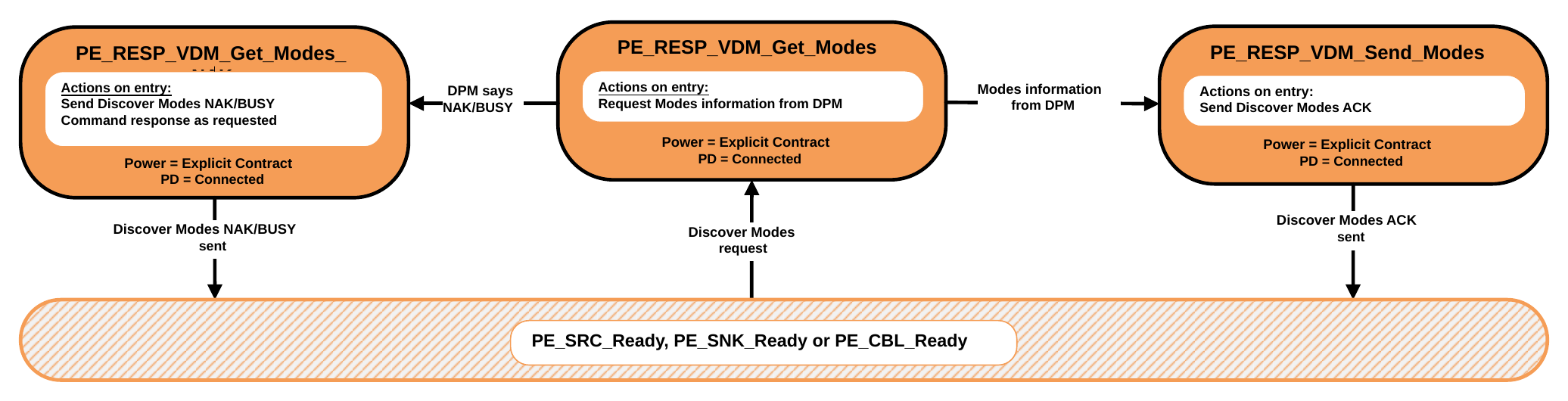
The Policy Engine transitions to the PE_RESP_VDM_Get_Modes State from either the PE_SRC_Ready, PE_SNK_Ready or PE_CBL_Ready State when:
- A Structured VDM Discover Modes Command Request is received.
On entry to the PE_RESP_VDM_Get_Modes State the Responder Shall Request Modes information from the Device Policy Manager.
The Policy Engine Shall transition to the PE_RESP_VDM_Send_Modes State when:
- Modes information is received from the Device Policy Manager.
The Policy Engine Shall transition to the PE_RESP_VDM_Get_Modes_NAK State when:
- The Device Policy Manager indicates that the response to the Discover Modes Command Request is NAK or BUSY.
9.2.23.3.1. PE_RESP_VDM_Send_Modes State
On entry to the PE_RESP_VDM_Send_Modes State the Responder Shall send the Structured VDM Discover Modes ACK Command response.
The Policy Engine Shall transition to either the PE_SRC_Ready, PE_SNK_Ready or PE_CBL_Ready State when:
- The Structured VDM Discover Modes ACK Command response has been sent.
9.2.23.3.2. PE_RESP_VDM_Get_Modes_NAK State
On entry to the PE_RESP_VDM_Get_Modes_NAK State the Policy Engine Shall send a Structured VDM Discover Modes NAK or BUSY Command response as indicated by the Device Policy Manager.
The Policy Engine Shall transition to either the PE_SRC_Ready, PE_SNK_Ready or PE_CBL_Ready State when:
- The Structured VDM Discover Modes NAK or BUSY Command response has been sent.
9.2.23.4. Receiving a Structured VDM Attention State Diagram
Figure 9.83 shows the State diagram for a Responder when receiving an Attention Command Request.
Figure 9.83. Receiving a Structured VDM Attention State Diagram
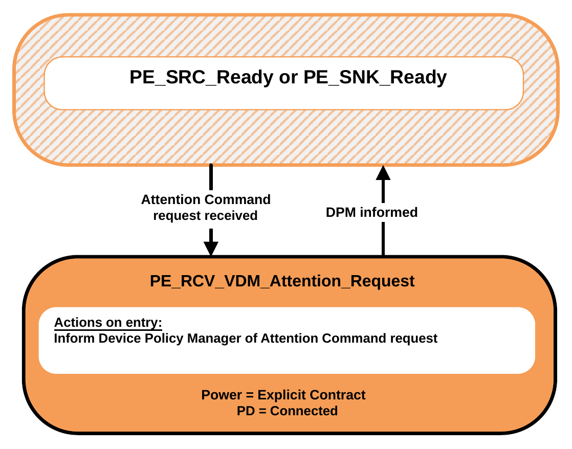
9.2.23.4.1. PE_RCV_VDM_Attention_Request State
The Policy Engine transitions to the PE_RCV_VDM_Attention_Request State from either the PE_SRC_Ready or PE_SNK_Ready State when:
- An Attention Command Request is received.
On entry to the PE_RCV_VDM_Attention_Request State the Policy Engine Shall inform the Device Policy Manager of the Attention Command Request.
The Policy Engine Shall transition to either the PE_SRC_Ready or PE_SNK_Ready State when:
- The Device Policy Manager has been informed.
9.2.24. DFP Structured VDM State Diagrams
The State Diagrams in this section Shall apply to all DFPs that support Structured VDMs.
9.2.24.1. DFP Structured VDM Mode Entry State Diagram
Figure 9.84 shows the State operation for a DFP when entering a Mode.
Figure 9.84. DFP VDM Mode Entry State Diagram
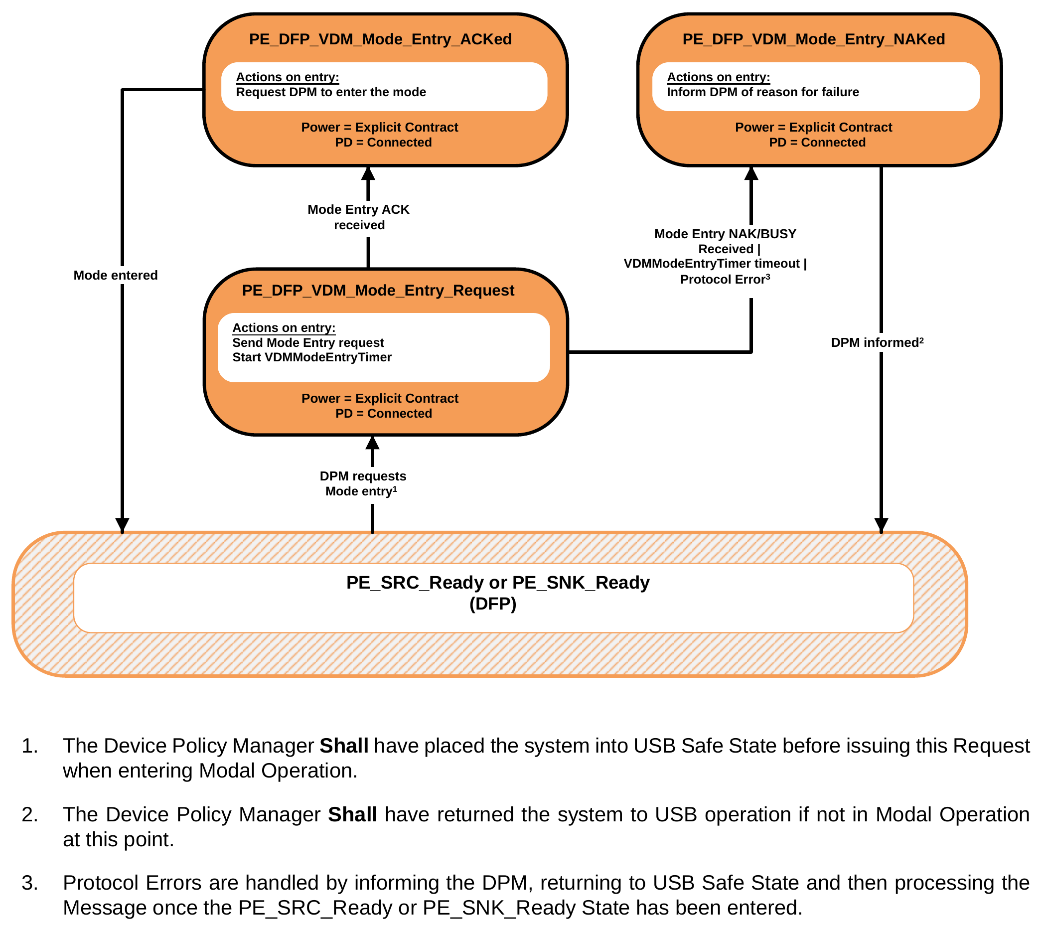
- The Device Policy Manager Shall have placed the system into USB Safe State before issuing this Request when entering Modal Operation.
- The Device Policy Manager Shall have returned the system to USB operation if not in Modal Operation at this point.
- Protocol Errors are handled by informing the DPM, returning to USB Safe State and then processing the Message once the PE_SRC_Ready or PE_SNK_Ready State has been entered.
9.2.24.1.1. PE_DFP_VDM_Mode_Entry_Request State
The Policy Engine transitions to the PE_DFP_VDM_Mode_Entry_Request State from either the PE_SRC_Ready or PE_SNK_Ready State for a DFP when:
- The Device Policy Manager requests that the Port Partner or a Cable Plug enter a Mode.
On entry to the PE_DFP_VDM_Mode_Entry_Request State the Policy Engine Shall send a Structured VDM Enter Mode Command Request and Shall start the VDMModeEntryTimer.
The Policy Engine Shall transition to the PE_DFP_VDM_Mode_Entry_ACKed State when:
- A Structured VDM Enter Mode ACK Command response is received.
The Policy Engine Shall transition to the PE_DFP_VDM_Mode_Entry_NAKed State when:
- A Structured VDM Enter Mode NAK or BUSY Command response is received or
- The VDMModeEntryTimer times out.
9.2.24.1.2. PE_DFP_VDM_Mode_Entry_ACKed State
On entry to the PE_DFP_VDM_Mode_Entry_ACKed State the Policy Engine Shall Request the Device Policy Manager to enter the Mode.
The Policy Engine Shall transition to either the PE_SRC_Ready or PE_SNK_Ready State for a DFP when:
- The Mode has been entered.
9.2.24.1.3. PE_DFP_VDM_Mode_Entry_NAKed State
On entry to the PE_DFP_VDM_Mode_Entry_NAKed State the Policy Engine Shall inform the Device Policy Manager of the reason for failure (NAK, BUSY, timeout or Protocol Error).
The Policy Engine Shall transition to either the PE_SRC_Ready or PE_SNK_Ready State for a DFP when:
- The Device Policy Manager has been informed.
9.2.24.2. DFP Structured VDM Mode Exit State Diagram
Figure 9.85 shows the State operation for a DFP when exiting a Mode.
Figure 9.85. DFP VDM Mode Exit State Diagram
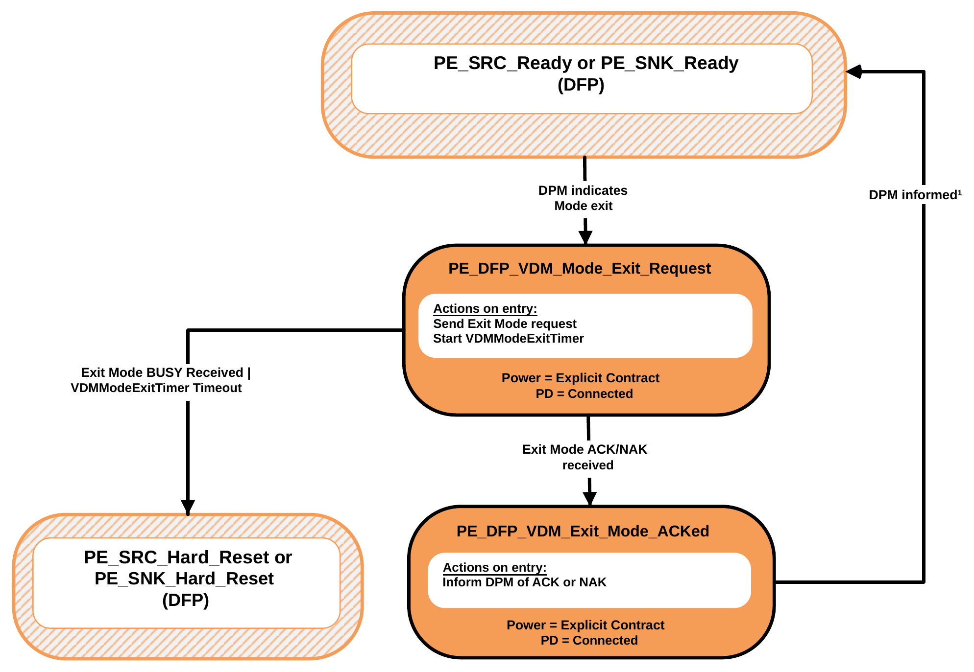
- The Device Policy Manager is required to return the system to USB operation at this point when exiting Modal Operation.
9.2.24.2.1. PE_DFP_VDM_Mode_Exit_Request State
The Policy Engine transitions to the PE_DFP_VDM_Mode_Exit_Request State from either the PE_SRC_Ready or PE_SNK_Ready State for a DFP when:
- The Device Policy Manager requests that the Port Partner or a Cable Plug exit a Mode.
On entry to the PE_DFP_VDM_Mode_Exit_Request State the Policy Engine Shall send a Structured VDM Exit Mode Command Request and Shall start the VDMModeExitTimer.
The Policy Engine Shall transition to the PE_DFP_VDM_Mode_Entry_ACKed State when:
- A Structured VDM Exit Mode ACK or NAK Command response is received.
The Policy Engine Shall transition to either the PE_SRC_Hard_Reset or PE_SNK_Hard_Reset State depending on the present Power Role when:
- A Structured VDM Exit Mode BUSY Command response is received or
- The VDMModeExitTimer times out.
9.2.24.2.2. PE_DFP_VDM_DFP_Mode_Exit_ACKed State
On Exit to the PE_DFP_VDM_Mode_Entry_ACKed State the Policy Engine Shall inform the Device Policy Manager Of the result: ACK or NAK.
The Policy Engine Shall transition to either the PE_SRC_Ready or PE_SNK_Ready State for a DFP when:
- The Device Policy Manager has been informed.
9.2.25. UFP Structured VDM State Diagrams
The State Diagrams in this section Shall apply to all UFPs that support Structured VDMs.
9.2.25.1. UFP Structured VDM Enter Mode State Diagram
Figure 9.86 shows the State diagram for a UFP in response to an Enter Mode Command.
Figure 9.86. UFP Structured VDM Enter Mode State Diagram
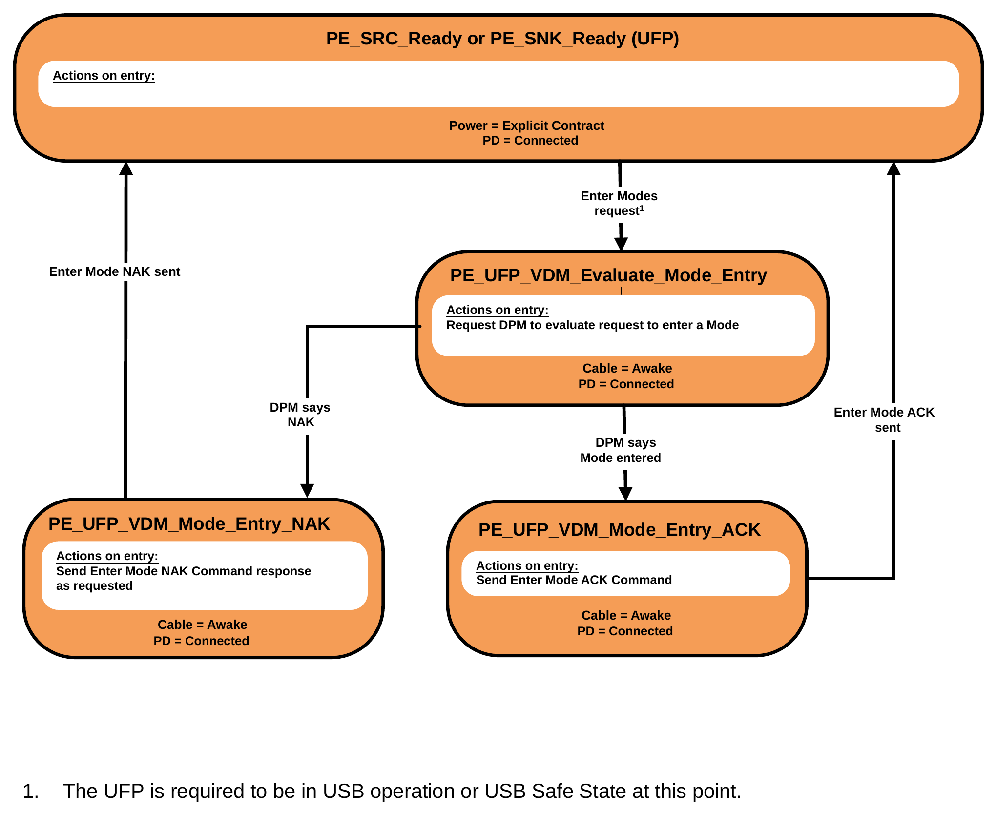
- The UFP is required to be in USB operation or USB Safe State at this point.
9.2.25.1.1. PE_UFP_VDM_Evaluate_Mode_Entry State
The Policy Engine transitions to the PE_UFP_VDM_Evaluate_Mode_Entry State from either the PE_SRC_Ready or PE_SNK_Ready State for a UFP when:
- A Structured VDM Enter Mode Command Request is received from the DFP.
On Entry to the PE_UFP_VDM_Evaluate_Mode_Entry State the Policy Engine Shall Request the Device Policy Manager to evaluate the Enter Mode Command Request and enter the Mode indicated in the Command Request if the Request is acceptable.
The Policy Engine Shall transition to the PE_UFP_VDM_Mode_Entry_ACK State when:
- The Device Policy Manager indicates that the Mode has been entered.
The Policy Engine Shall transition to the PE_UFP_VDM_Mode_Entry_NAK State when:
- The Device Policy Manager indicates that the response to the Mode Request is NAK.
9.2.25.1.2. PE_UFP_VDM_Mode_Entry_ACK State
On entry to the PE_UFP_VDM_Mode_Entry_ACK State the Policy Engine Shall send a Structured VDM Enter Mode ACK Command response.
The Policy Engine Shall transition to either the PE_SRC_Ready or PE_SNK_Ready State for a UFP when:
- The Structured VDM Enter Mode ACK Command response has been sent.
9.2.25.1.3. PE_UFP_VDM_Mode_Entry_NAK State
On entry to the PE_UFP_VDM_Mode_Entry_NAK State the Policy Engine Shall send a Structured VDM Enter Mode NAK Command response as indicated by the Device Policy Manager.
The Policy Engine Shall transition to either the PE_SRC_Ready or PE_SNK_Ready State for a UFP when:
- The Structured VDM Enter Mode NAK Command response has been sent.
9.2.25.2. UFP Structured VDM Exit Mode State Diagram
Figure 9.87 shows the State diagram for a UFP in response to an Exit Mode Command.
Figure 9.87. UFP Structured VDM Exit Mode State Diagram
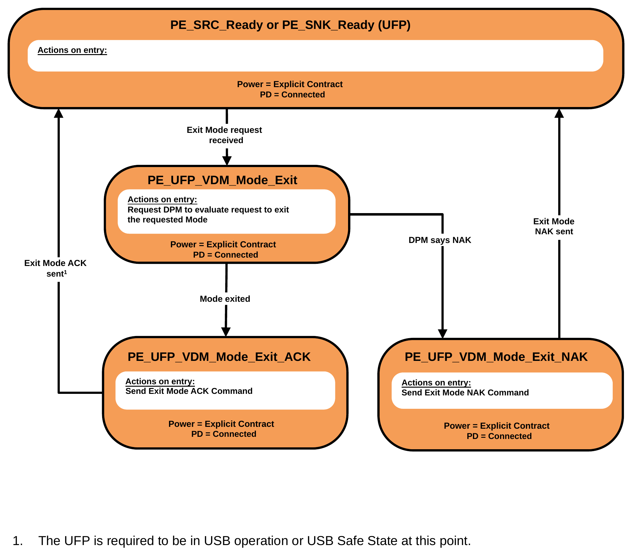
- The UFP is required to be in USB operation or USB Safe State at this point.
9.2.25.2.1. PE_UFP_VDM_Mode_Exit State
The Policy Engine transitions to the PE_UFP_VDM_Mode_Exit State from either the PE_SRC_Ready or PE_SNK_Ready State for a UFP when:
- A Structured VDM Exit Mode Command Request is received from the DFP.
On entry to the PE_UFP_VDM_Mode_Exit State the Policy Engine Shall Request the Device Policy Manager to exit the Mode indicated in the Command.
The Policy Engine Shall transition to the PE_UFP_VDM_Mode_Exit_ACK State when:
- The Device Policy Manager indicates that the Mode has been exited.
The Policy Engine Shall transition to the PE_UFP_VDM_Mode_Exit_NAK State when:
- The Device Policy Manager indicates that the Command response to the Exit Mode Command Request is NAK.
9.2.25.2.2. PE_UFP_VDM_Mode_Exit_ACK State
On entry to the PE_UFP_VDM_Mode_Exit_ACK State the Policy Engine Shall send a Structured VDM Exit Mode ACK Command response.
The Policy Engine Shall transition to either the PE_SRC_Ready or PE_SNK_Ready State for a UFP when:
- The Structured VDM Exit Mode ACK Command response has been sent.
9.2.25.2.3. PE_UFP_VDM_Mode_Exit_NAK State
On entry to the PE_UFP_VDM_Mode_Exit_NAK State the Policy Engine Shall send a Structured VDM Exit Mode NAK Command response as indicated by the Device Policy Manager.
The Policy Engine Shall transition to either the either the PE_SRC_Ready or PE_SNK_Ready State for a UFP when:
- The Structured VDM Exit Mode NAK Command response has been sent.
9.2.26. Cable Plug Specific State Diagrams
The State Diagrams in this section Shall apply to all Cable Plugs that support Structured VDMs.
9.2.26.1. Cable Plug Cable Ready State Diagram
Figure 9.88 shows the Cable Ready State diagram for a Cable Plug.
Figure 9.88. Cable Ready State Diagram
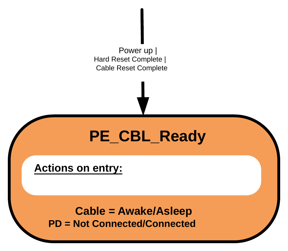
9.2.26.1.1. PE_CBL_Ready State
The PE_CBL_Ready State shown in the following sections is the normal operational State for a Cable Plug and where it starts after power up or a Hard/Cable Reset.
9.2.26.2. Soft/Hard/Cable Reset
9.2.26.2.1. Cable Plug Soft Reset State Diagram
Figure 9.89 shows the Cable Plug State diagram for a Soft Reset.
Figure 9.89. Cable Plug Soft Reset State Diagram
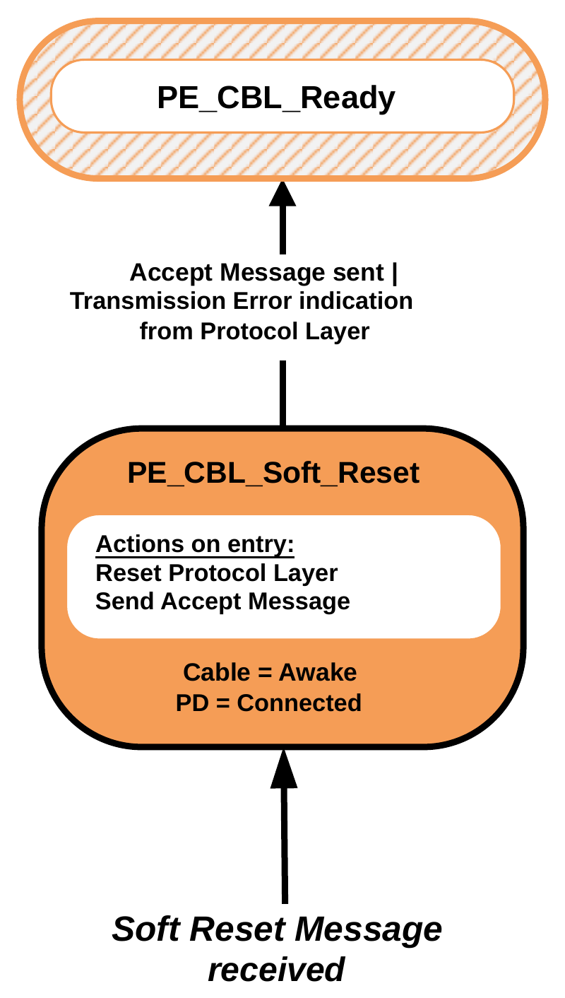
9.2.26.2.1.1. PE_CBL_Soft_Reset State
The PE_CBL_Soft_Reset State Shall be entered from any State when a Soft_Reset Message is received from the Protocol Layer.
On entry to the PE_CBL_Soft_Reset State the Policy Engine Shall reset the Protocol Layer in the Cable Plug and Shall then Request the Protocol Layer to send an Accept Message.
The Policy Engine Shall transition to the PE_CBL_Ready State when:
- The Accept Message has been sent or
- The Protocol Layer indicates that a transmission error has occurred.
9.2.26.2.2. Cable Plug Hard Reset State Diagram
Figure 9.90 shows the Cable Plug State diagram for a Hard Reset.
Figure 9.90. Cable Plug Hard Reset State Diagram
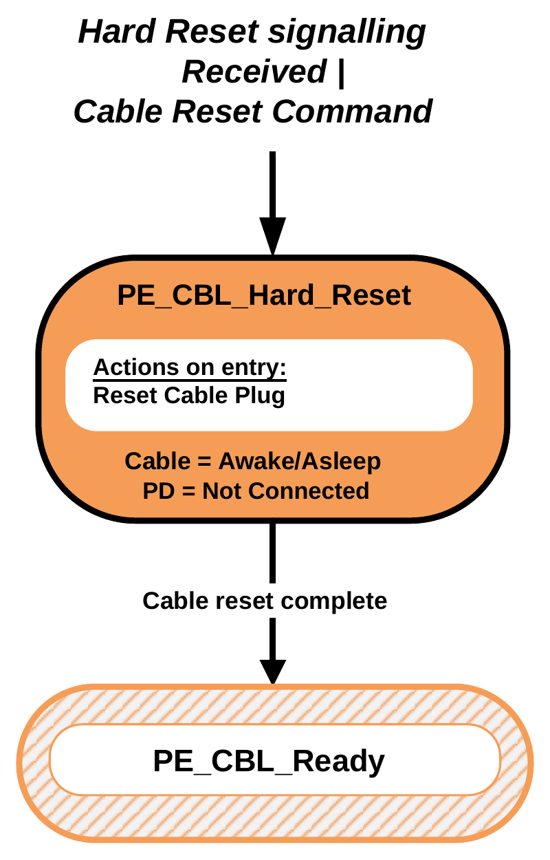
9.2.26.2.2.1. PE_CBL_Hard_Reset State
The PE_CBL_Hard_Reset State Shall be entered from any State when either Hard Reset Signaling or Cable Reset Signaling is detected.
On entry to the PE_CBL_Hard_Reset State the Policy Engine Shall reset the Cable Plug (equivalent to a power cycle). The Policy Engine Shall transition to the PE_CBL_Ready State when:
- The Cable Plug reset is complete.
9.2.26.2.3. DFP/VCONN Source SOP'/SOP" Soft Reset or Cable Reset of a Cable Plug or VPD State Diagram
This figure shows the State diagram for the Policy Engine in a VCONN Source when performing a Soft Reset or Cable Reset of a Cable Plug or VPD on SOP'/SOP". The following sections describe operation in each of the states.
Figure 9.91. DFP/VCONN Source Soft Reset or Cable Reset of a Cable Plug or VPD State Diagram
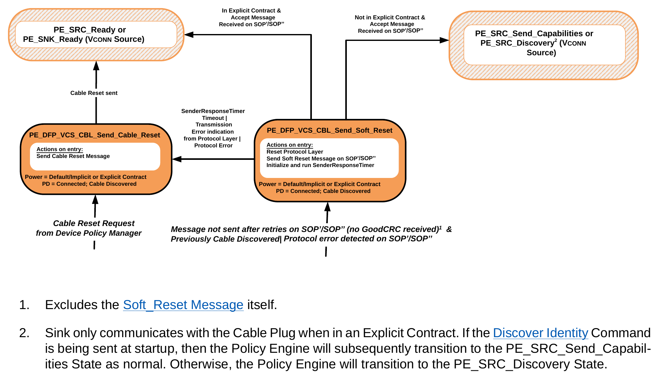
- Excludes the Soft_Reset Message itself.
- Sink only communicates with the Cable Plug when in an Explicit Contract. If the Discover Identity Command is being sent at startup, then the Policy Engine will subsequently transition to the PE_SRC_Send_Capabilities State as normal. Otherwise, the Policy Engine will transition to the PE_SRC_Discovery State.
9.2.26.2.3.1. PE_DFP_VCS_CBL_Send_Soft_Reset State
The PE_DFP_VCS_CBL_Send_Soft_Reset State Shall be entered from any State when a Protocol Error is detected on SOP'/SOP'' by the Protocol Layer (see Section 7.1.1) or when a Message has not been sent after retries on SOP'/SOP'' while communicating with a Cable Plug/VPD and when there was previous communication with the Cable Plug that did not result in a Transmission Error or whenever the Device Policy Manager directs a Soft Reset on SOP'/SOP''.
On entry to the PE_DFP_VCS_CBL_Send_Soft_Reset State the DFP Policy Engine Shall Request the SOP'/SOP'' Protocol Layer to perform a Soft Reset, then Shall send a Soft_Reset Message on SOP'/SOP'' to the Cable Plug/VPD, and initialize and run the SenderResponseTimer.
The Policy Engine Shall transition to either the PE_SRC_Ready or PE_SNK_Ready State, depending on the DFP VCONN Source's Power Role, when:
- There is no Explicit Contract in place and
- An Accept Message has been received on SOP'/SOP''.
The Policy Engine Shall transition to either the PE_SRC_Send_Capabilities State or PE_SRC_Discovery State, depending on the DFP's VCONN Source's Power Role, when:
- There is an Explicit Contract in place and
- An Accept Message has been received on SOP'/SOP''.
The Policy Engine Shall transition to the PE_DFP_VCS_CBL_Send_Cable_Reset State when:
- A SenderResponseTimer timeout occurs
- Or the Protocol Layer indicates that a transmission error has occurred
- Or when a Protocol Error is detected on SOP'/SOP'' by the Protocol Layer.
9.2.26.2.3.2. PE_DFP_VCS_CBL_Send_Cable_Reset State
The PE_DFP_VCS_CBL_Send_Cable_Reset State Shall be entered from any State when the Device Policy Manager requests a Cable Reset.
On entry to the PE_DFP_VCS_CBL_Send_Cable_Reset State the DFP Policy Engine Shall Request the Protocol Layer to send Cable Reset Signaling.
The Policy Engine Shall transition to either the PE_SRC_Ready or PE_SNK_Ready State, depending on the VCONN Source's Power Role, when:
- Cable Reset Signaling has been sent.
9.2.26.2.4. UFP/VCONN Source SOP'/SOP'' Soft Reset of a Cable Plug or VPD State Diagram
This figure shows the State diagram for the UFP Policy Engine in a VCONN Source when performing a Soft Reset of a Cable Plug or VPD on SOP'/SOP''. The following sections describe operation in each of the states.
Figure 9.92. UFP/VCONN Source Soft Reset of a Cable Plug or VPD State Diagram
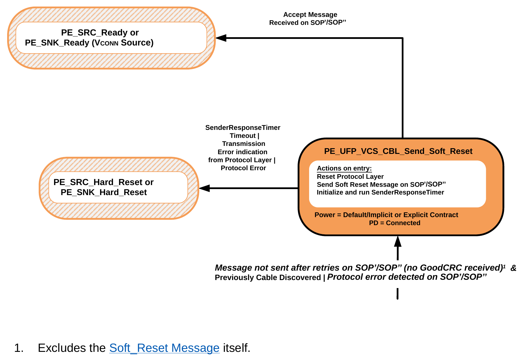
- Excludes the Soft_Reset Message itself.
9.2.26.2.4.1. PE_UFP_VCS_CBL_Send_Soft_Reset State
The PE_UFP_VCS_CBL_Send_Soft_Reset State Shall be entered from any State when a Protocol Error is detected on SOP'/SOP'' by the Protocol Layer (see Section 7.1.1) or when a Message has not been sent after retries on
SOP'/SOP'' while communicating with a Cable Plug/VPD and when there was previous communication with the Cable Plug that did not result in a Transmission Error or whenever the Device Policy Manager directs a Soft Reset on SOP'/SOP''.
On entry to the PE_UFP_VCS_CBL_Send_Soft_Reset State the Policy Engine Shall Request the SOP'/SOP'' Protocol Layer to perform a Soft Reset, then Shall send a Soft_Reset Message on SOP'/SOP'' to the Cable Plug, and initialize and run the SenderResponseTimer.
The Policy Engine Shall transition to either the PE_SRC_Ready or PE_SNK_Ready State, depending on the UFP VCONN Source's Power Role, when:
- An Accept Message has been received on SOP'/SOP''.
The Policy Engine Shall transition to either the PE_SRC_Hard_Reset or PE_SNK_Hard_Reset State, depending on the UFP VCONN Source's Power Role, when:
- A SenderResponseTimer timeout occurs
- Or the Protocol Layer indicates that a transmission error has occurred
- Or when a Protocol Error is detected on SOP'/SOP'' by the Protocol Layer.
9.2.26.2.5. Source Startup Structured VDM Discover Identity of a Cable Plug State Diagram
Figure 9.93 shows the State diagram for Source discovery of identity information from a Cable Plug during the startup sequence.
Figure 9.93. Source Startup Structured VDM Discover Identity State Diagram
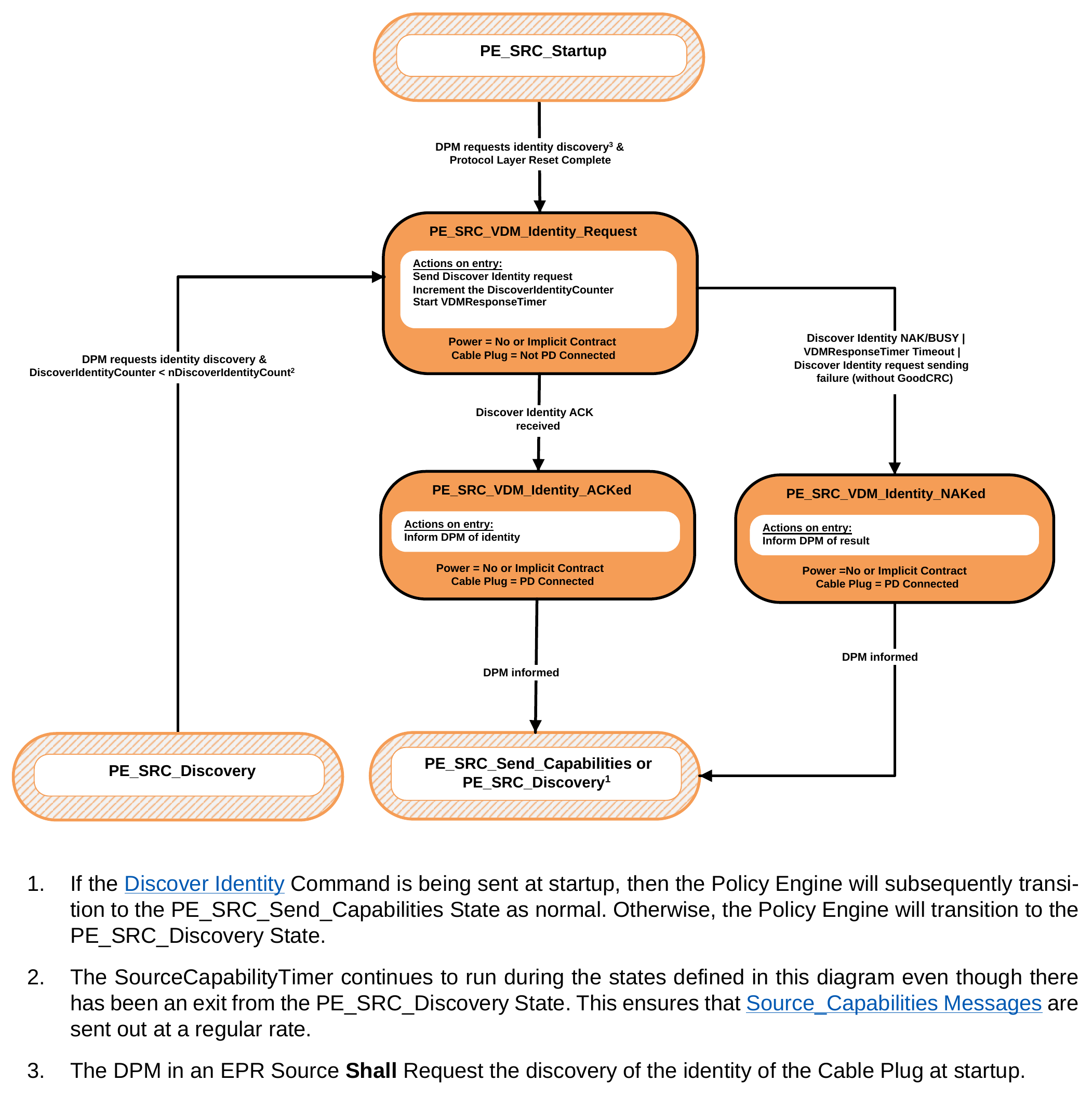
- If the Discover Identity Command is being sent at startup, then the Policy Engine will subsequently transition to the PE_SRC_Send_Capabilities State as normal. Otherwise, the Policy Engine will transition to the PE_SRC_Discovery State.
- The SourceCapabilityTimer continues to run during the states defined in this diagram even though there has been an exit from the PE_SRC_Discovery State. This ensures that Source_Capabilities Messages are sent out at a regular rate.
- The DPM in an EPR Source Shall Request the discovery of the identity of the Cable Plug at startup.
9.2.26.2.5.1. PE_SRC_VDM_Identity_Request State
The Policy Engine Shall transition to the PE_SRC_VDM_Identity_Request State from the PE_SRC_Startup State when:
- The Device Policy Manager requests the discovery of the identity of the Cable Plug.
The Policy Engine Shall transition to the PE_SRC_VDM_Identity_Request State from the PE_SRC_Discovery State when:
- The Device Policy Manager requests the discovery of the identity of the Cable Plug and
- The DiscoverIdentityCounter < nDiscoverIdentityCount.
Even though there has been a transition out of the PE_SRC_Discovery State the SourceCapabilityTimer Shall continue to run during the states shown in Figure 9.93 and Shall Not be initialized on re-entry to PE_SRC_Discovery.
Note: An EPR Source is required to discover the identity of the Cable Plug prior to entering the First Explicit Contract (see Section 7.30.1)
On entry to the PE_SRC_VDM_Identity_Request State the Policy Engine Shall send a Structured VDM Discover Identity Command Request, Shall increment the DiscoverIdentityCounter and Shall start the VDMResponseTimer.
The Policy Engine Shall transition to the PE_SRC_VDM_Identity_ACKed State when:
- A Structured VDM Discover Identity ACK Command response is received. The Policy Engine Shall transition to the PE_SRC_VDM_Identity_NAKed State when:
-
A Structured VDM Discover Identity NAK or BUSY Command response is received or
-
The VDMResponseTimer times out or
-
The Structured VDM Discover Identity Command Request Message sending fails (no GoodCRC Message
received after retries).
-
9.2.26.2.5.2. PE_SRC_VDM_Identity_ACKed State
On entry to the PE_SRC_VDM_Identity_ACKed State the Policy Engine Shall inform the Device Policy Manager of the Identity information.
The Policy Engine Shall transition back to either the PE_SRC_Send_Capabilities or PE_SRC_Discovery State when:
- The Device Policy Manager has been informed.
9.2.26.2.5.3. PE_SRC_VDM_Identity_NAKed State
On entry to the PE_SRC_VDM_Identity_NAKed State the Policy Engine Shall inform the Device Policy Manager of the result (NAK, BUSY or timeout).
The Policy Engine Shall transition back to either the PE_SRC_Send_Capabilities or PE_SRC_Discovery State when:
- The Device Policy Manager has been informed.
9.2.26.2.6. Cable Plug Mode Entry/Exit
9.2.26.2.6.1. Cable Plug Structured VDM Enter Mode State Diagram
Figure 9.94 shows the State diagram for a Cable Plug in response to an Enter Mode Command.
Figure 9.94. Cable Plug Structured VDM Enter Mode State Diagram
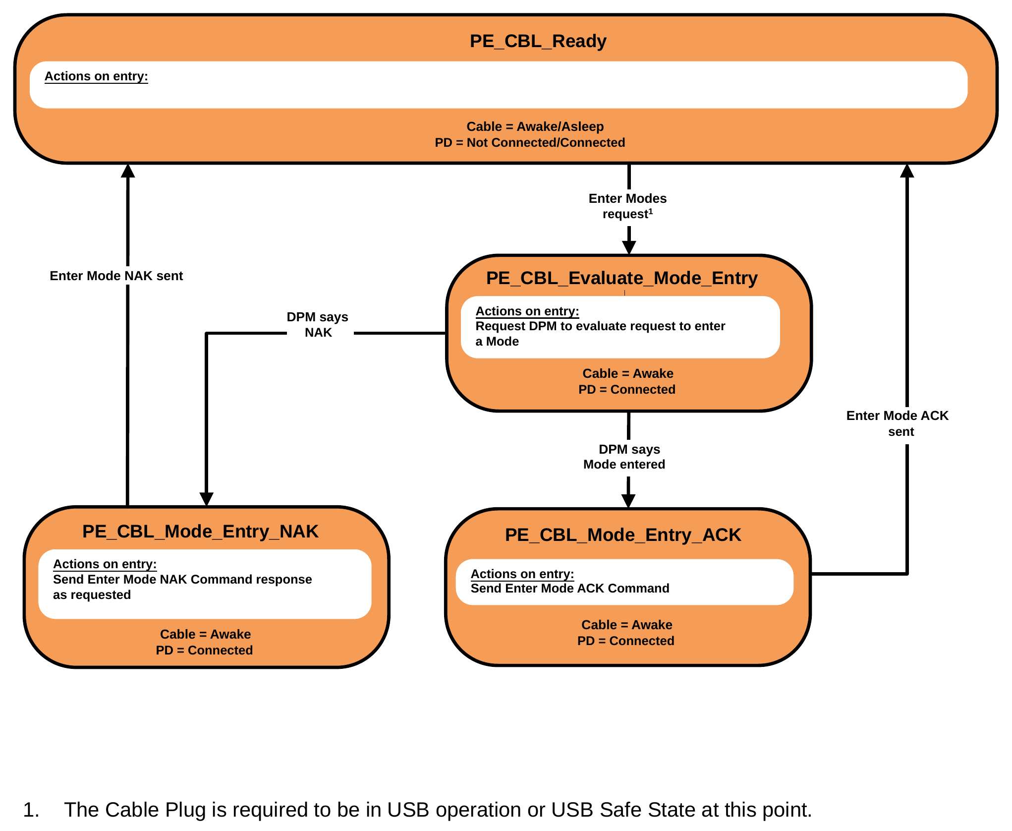
- The Cable Plug is required to be in USB operation or USB Safe State at this point.
PE_CBL_Evaluate_Mode_Entry State
The Policy Engine transitions to the PE_CBL_Evaluate_Mode_Entry State from the PE_CBL_Ready State when:
- A Structured VDM Enter Mode Command Request is received from the DFP.
On Entry to the PE_CBL_Evaluate_Mode_Entry State the Policy Engine Shall Request the Device Policy Manager to evaluate the Enter Mode Command Request and enter the Mode indicated in the Command Request if the Request is acceptable.
The Policy Engine Shall transition to the PE_CBL_Mode_Entry_ACK State when:
- The Device Policy Manager indicates that the Mode has been entered. The Policy Engine Shall transition to the PE_CBL_Mode_Entry_NAK State when:
- The Device Policy Manager indicates that the response to the Mode Request is NAK.
PE_CBL_Mode_Entry_ACK State
On entry to the PE_CBL_Mode_Entry_ACK State the Policy Engine Shall send a Structured VDM Enter Mode ACK Command response.
The Policy Engine Shall transition to the PE_CBL_Ready State when:
- The Structured VDM Enter Mode ACK Command response has been sent.
PE_CBL_Mode_Entry_NAK State
On entry to the PE_CBL_Mode_Entry_NAK State the Policy Engine Shall send a Structured VDM Enter Mode NAK Command response as indicated by the Device Policy Manager.
The Policy Engine Shall transition to the PE_CBL_Ready State when:
- The Structured VDM Enter Mode NAK Command response has been sent.
9.2.26.2.6.2. Cable Plug Structured VDM Exit Mode State Diagram
- Figure 9.95 shows the State diagram for a Cable Plug in response to an Exit Mode Command.
Figure 9.95. Cable Plug Structured VDM Exit Mode State Diagram
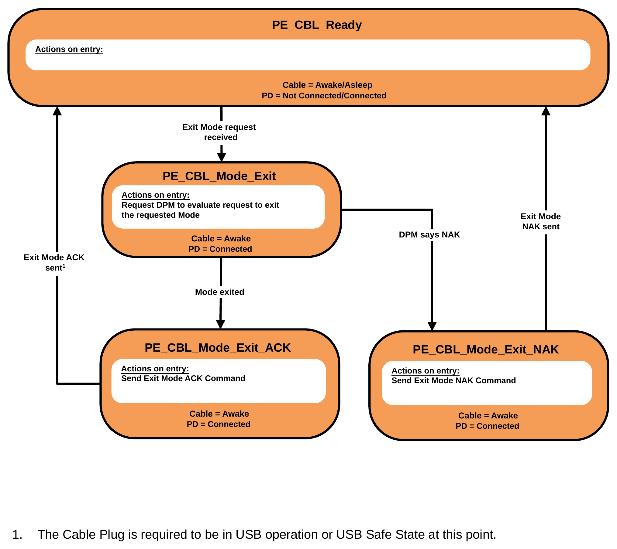
- The Cable Plug is required to be in USB operation or USB Safe State at this point.
PE_CBL_Mode_Exit State
The Policy Engine transitions to the PE_CBL_Mode_Exit State from the PE_CBL_Ready State when:
- A Structured VDM Exit Mode Command Request is received from the DFP.
On entry to the PE_CBL_Mode_Exit State the Policy Engine Shall Request the Device Policy Manager to exit the Mode indicated in the Command.
The Policy Engine Shall transition to the PE_CBL_Mode_Exit_ACK State when:
- The Device Policy Manager indicates that the Mode has been exited. The Policy Engine Shall transition to the PE_CBL_Mode_Exit_NAK State when:
- The Device Policy Manager indicates that the Command response to the Exit Mode Command Request is NAK.
PE_CBL_Mode_Exit_ACK State
On entry to the PE_CBL_Mode_Exit_ACK State the Policy Engine Shall send a Structured VDM Exit Mode ACK Command response.
The Policy Engine Shall transition to the PE_CBL_Ready State when:
- The Structured VDM Exit Mode ACK Command response has been sent.
PE_CBL_Mode_Exit_NAK State
On entry to the PE_CBL_Mode_Exit_NAK State the Policy Engine Shall send a Structured VDM Exit Mode NAK Command response as indicated by the Device Policy Manager.
The Policy Engine Shall transition to the PE_CBL_Ready State when:
- The Structured VDM Exit Mode NAK Command response has been sent.
9.2.26.3. EPR Mode State Diagrams
9.2.26.3.1. Source EPR Mode Entry State Diagram
Figure 9.96 shows the State diagram for an EPR Source in response to an EPR_Mode Message.
Figure 9.96. Source EPR Mode Entry State Diagram
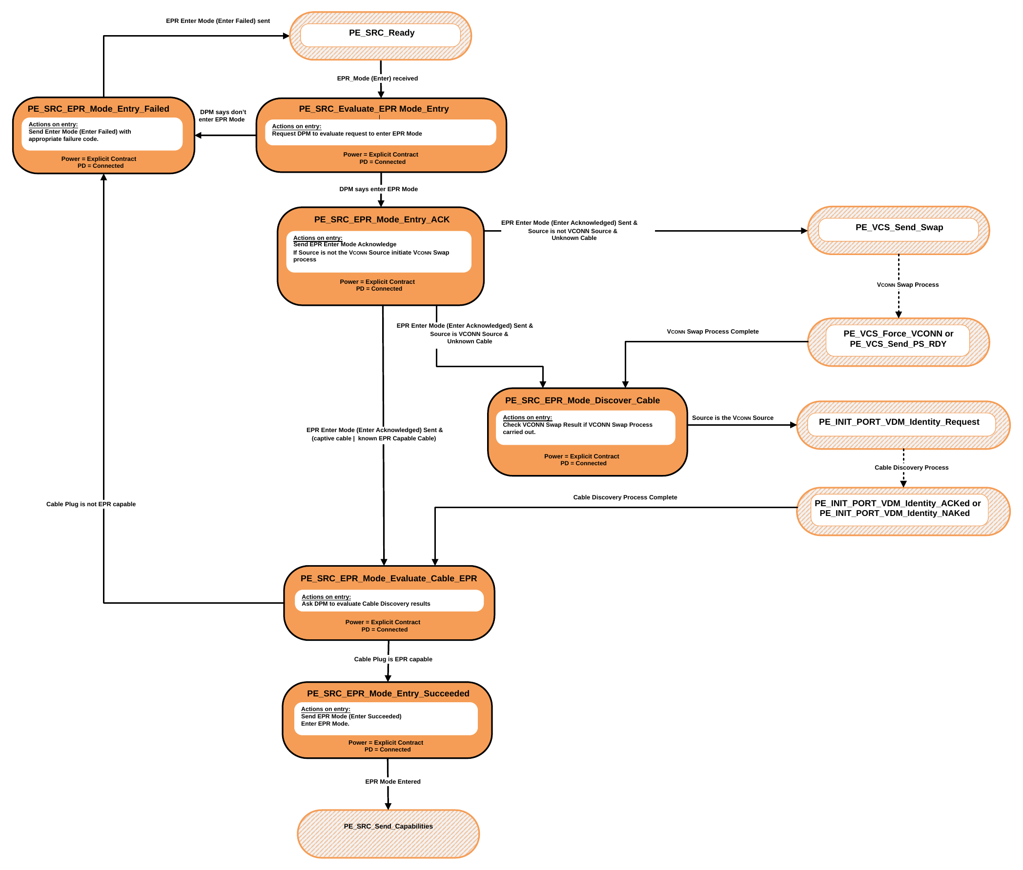
9.2.26.3.1.1. PE_SRC_Evaluate_EPR_Mode_Entry State
The Policy Engine transitions to the PE_SRC_Evaluate_EPR_Mode_Entry State from the PE_SRC_Ready State when:
- An
EPR_Mode(Enter) Message is received from the Sink.
On Entry to the PE_SRC_Evaluate_EPR_Mode_Entry State the Policy Engine Shall Request the Device Policy Manager to evaluate the EPR_Mode (Enter) Message.
The Policy Engine Shall transition to the PE_SRC_EPR_Mode_Entry_Ack State when:
- The Device Policy Manager indicates that EPR Mode can be entered.
The Policy Engine Shall transition to the PE_SRC_EPR_Mode_Entry_Failed State when:
- The Device Policy Manager indicates that the EPR Mode is not to be entered.
9.2.26.3.1.2. PE_SRC_EPR_Mode_Entry_Ack State
On entry to the PE_SRC_EPR_Mode_Entry_Ack State the Policy Engine Shall send a EPR_Mode (Enter Acknowledged) Message.
The Policy Engine Shall transition to the PE_SRC_EPR_Mode_Evaluate_Cable_EPR State when:
- The
EPR_Mode(Enter Acknowledged) Message has been sent and - The Source is not the VCONN Source and
- The cable is a captive cable or a known EPR Cable.
The Policy Engine Shall transition to the PE_VCS_Send_Swap State when:
- The
EPR_Mode(Enter Acknowledged) Message has been sent and - The Source is not the VCONN Source and
- The cable is unknown.
The Policy Engine Shall transition to the PE_SRC_EPR_Mode_Discover_Cable State when:
- The
EPR_Mode(Enter Acknowledged) Message has been sent and - The Source is the VCONN Source and
- The cable is unknown.
9.2.26.3.1.3. PE_SRC_EPR_Mode_Discover_Cable State
The Policy Engine transitions to the PE_SRC_EPR_Mode_Discover_Cable State from the PE_VCS_Force_VCONN State or PE_VCS_Send_Ps_Rdy State when:
- A Source initiated
VCONN Swapprocess has completed.
The Policy Engine Shall transition to the PE_INIT_Port_VDM_Identity_Request State in order to perform Cable Plug discovery when:
- The Source is the VCONN Source.
The Policy Engine Shall transition to the PE_SRC_EPR_Mode_Entry_Failed State when:
- The
VCONN Swapprocess failed (the Source is not the VCONN Source).
9.2.26.3.1.4. PE_SRC_EPR_Mode_Evaluate_Cable_EPR State
In the PE_SRC_EPR_Mode_Evaluate_Cable_EPR State the Policy Engine requests the DPM to evaluate the Cable Discovery results.
The Policy Engine Shall transition to the PE_SRC_EPR_Mode_Entry_Succeeded State when:
- The Cable Plug is capable of EPR Mode.
The Policy Engine Shall transition to the PE_SRC_EPR_Mode_Entry_Failed State when:
- The Cable Plug is not capable of EPR Mode.
9.2.26.3.1.5. PE_SRC_EPR_Mode_Entry_Succeeded State
On entry to the PE_SRC_EPR_Mode_Entry_Succeeded State the Policy Engine Shall send a EPR_Mode (Enter Succeeded) Message and enter EPR Mode.
The Policy Engine Shall transition to the PE_SRC_Send_Capabilities State when:
- EPR Mode has been entered.
9.2.26.3.1.6. PE_SRC_EPR_Mode_Entry_Failed State
On entry to the PE_SRC_EPR_Mode_Entry_Failed State the Policy Engine Shall send a EPR_Mode (Enter Failed) Message.
The Policy Engine Shall transition to the PE_SRC_Ready State when:
- The
EPR_Mode(Enter Failed) Message has been sent.
9.2.26.3.2. Sink EPR Mode Entry State Diagram
Figure 9.97 shows the State diagram for an EPR Sink initiating the EPR Mode Entry process.
Figure 9.97. Sink EPR Mode Entry State Diagram
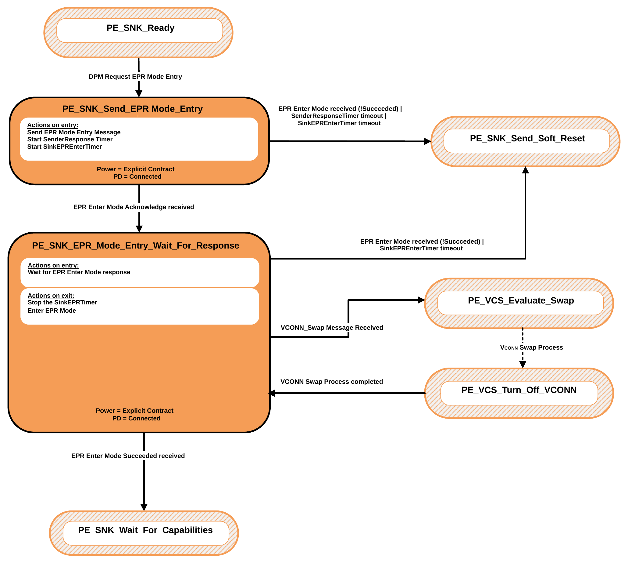
9.2.26.3.2.1. PE_SNK_Send_EPR_Mode_Entry State
The Policy Engine transitions to the PE_SNK_Send_EPR_Mode_Entry State from the PE_SNK_Ready State when:
- The DPM requests entry into EPR Mode.
On Entry to the PE_SNK_Send_EPR_Mode_Entry State the Policy Engine Shall send an EPR_Mode (Enter) Message and starts the SenderResponseTimer and the SinkEPREnterTimer.
Note: The SinkEPREnterTimer Shall continue to run in every State until it is stopped or times out. The Policy Engine Shall transition to the PE_SNK_EPR_Mode_Wait_For_Response State when:
- An
EPR_Mode(Enter Acknowledge) Message is received.
The Policy Engine Shall transition to the PE_SNK_Send_Soft_Reset State when:
- An
EPR_ModeMessage is received which is not Enter Succeeded or - The SenderResponseTimer times out or
- The SinkEPREnterTimer times out.
9.2.26.3.2.2. PE_SNK_EPR_Mode_Wait_For_Response State
In the State the Policy Engine waits for a confirmation that the EPR Mode entry Request has succeeded. On exit from the PE_SNK_EPR_Mode_Wait_For_Response State the Policy Engine Shall stop the SinkEPREnterTimer and enter EPR Mode.
The Policy Engine Shall transition to the PE_SNK_Send_Soft_Reset State when:
- An
EPR_ModeMessage is received which is not Enter Succeeded or - The SinkEPREnterTimer times out.
The Policy Engine Shall transition to the PE_VCS_Evaluate_Swap State when:
- A
VCONN_SwapMessage is received.
The Policy Engine Shall transition back from the PE_VCS_Turn_Off_VCONN State to the PE_SNK_EPR_Mode_Wait_For_Response State when:
- The
VCONN Swapprocess has completed.
The Policy Engine Shall transition to the PE_SNK_Wait_for_Capabilities State when:
- An
EPR_Mode(Enter Succeeded) Message has been received.
9.2.26.3.3. Source EPR Mode Exit State Diagram
Figure 9.98 shows the State diagram for an EPR Source initiating the EPR Mode Exit process.
Figure 9.98. Source EPR Mode Exit State Diagram
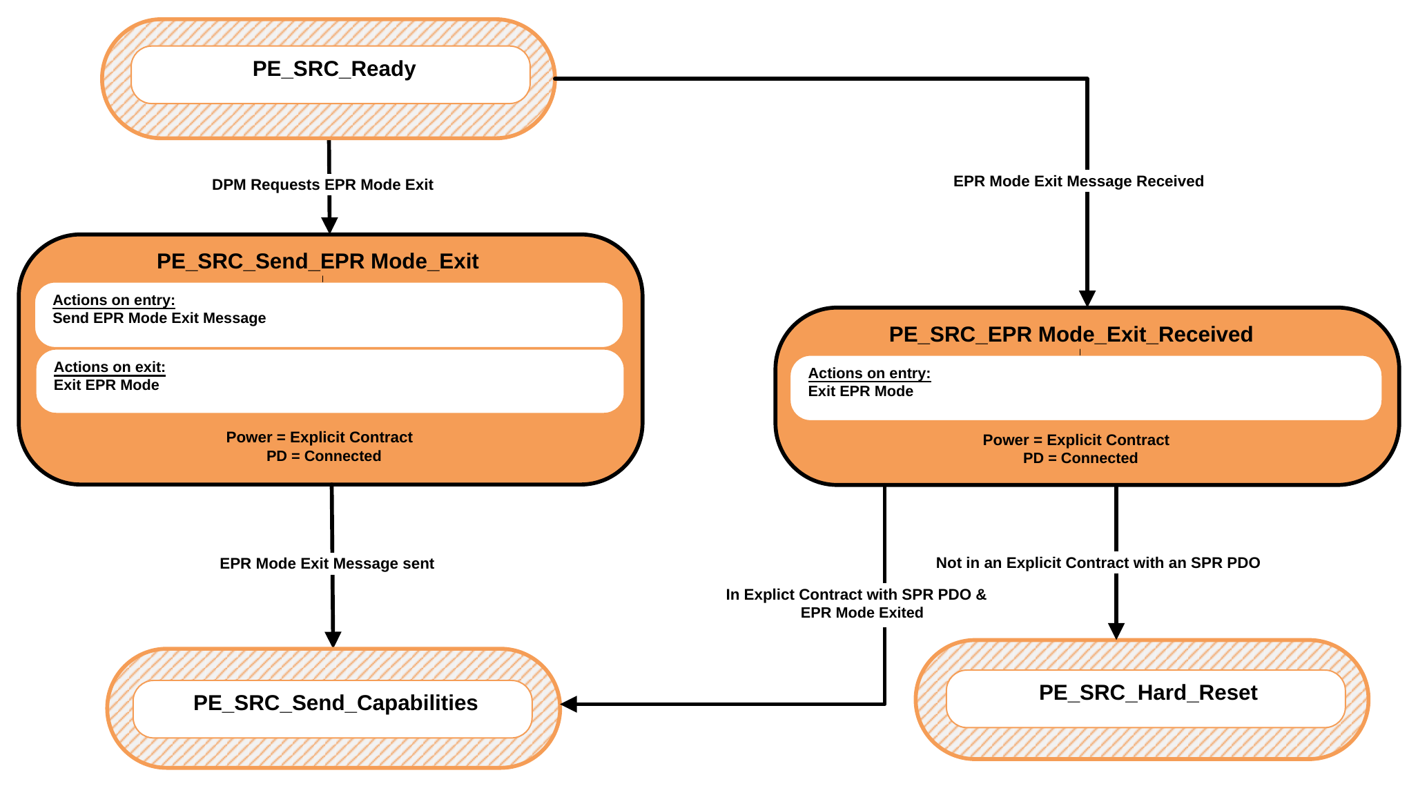
9.2.26.3.3.1. PE_SRC_Send_EPR_Mode_Exit State
The Policy Engine transitions to the PE_SRC_Send_EPR_Mode_Exit State from the PE_SRC_Ready State when:
- The DPM requests exit from EPR Mode.
On Entry to the PE_SRC_Send_EPR_Mode_Exit State the Policy Engine Shall send an EPR_Mode (Exit) Message. On Exit from the PE_SRC_Send_EPR_Mode_Exit State the Policy Engine Shall exit EPR Mode.
The Policy Engine Shall transition to the PE_SRC_Send_Capabilities State when:
- The
EPR_Mode(Exit) Message has been sent.
9.2.26.3.3.2. PE_SRC_EPR_Mode_Exit_Received State
The Policy Engine transitions to the PE_SRC_EPR_Mode_Exit_Received State from the PE_SRC_Ready State when:
- An
EPR_Mode(Exit) Message is received.
On Entry to the PE_SRC_EPR_Mode_Exit_Received State the Policy Engine Shall exit EPR Mode. The Policy Engine Shall transition to the PE_SRC_Send_Capabilities State when:
- In an Explicit Contract with an SPR PDO or APDO and
- EPR Mode has been exited.
The Policy Engine Shall transition to the PE_SRC_Hard_Reset State when:
- Not in an Explicit Contract with an SPR PDO or APDO.
9.2.26.3.4. Sink EPR Mode Exit State Diagram
Figure 9.99 shows the State diagram for an EPR Sink initiating the EPR Mode Exit process.
Figure 9.99. Sink EPR Mode Exit State Diagram
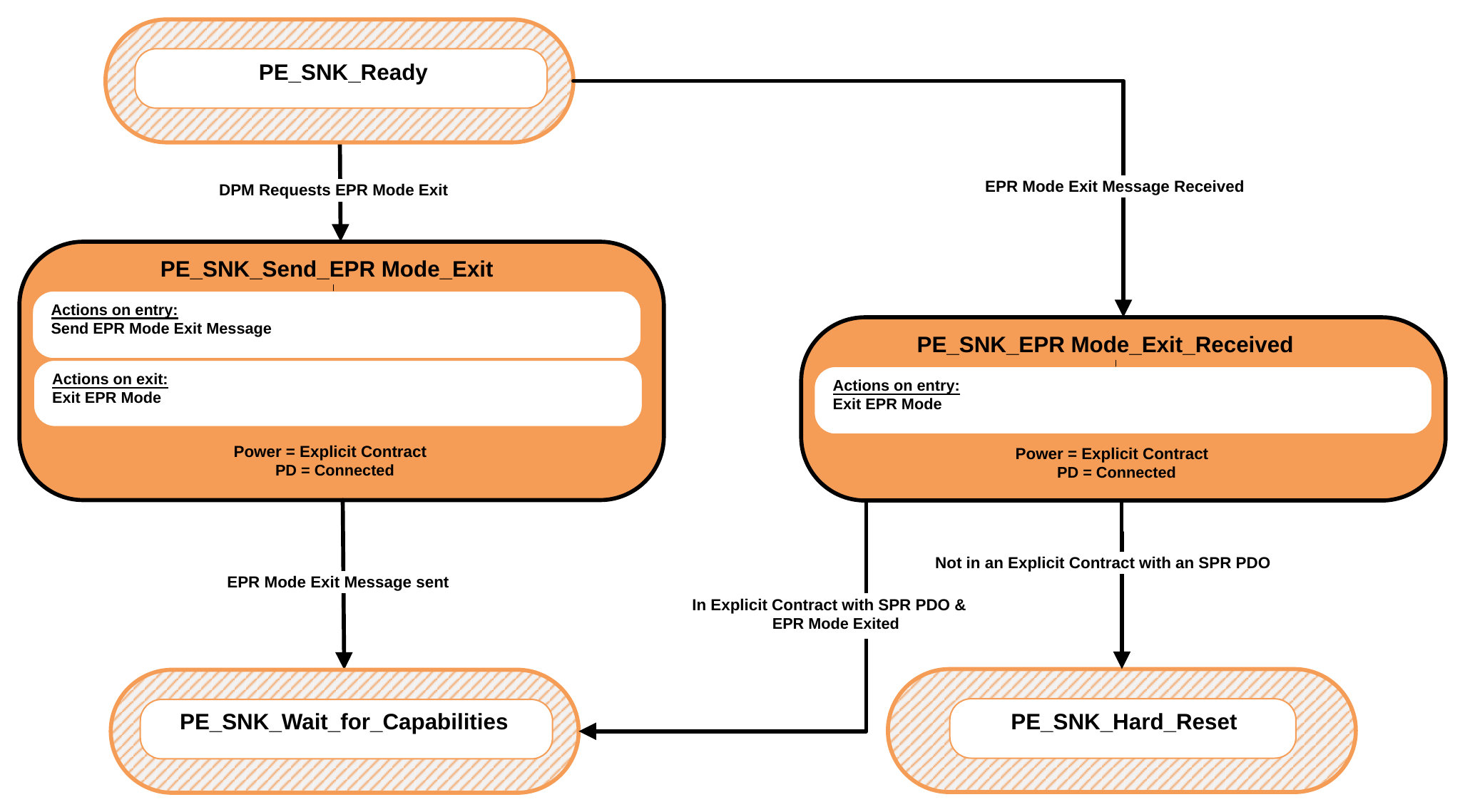
9.2.26.3.4.1. PE_SNK_Send_EPR_Mode_Exit State
The Policy Engine transitions to the PE_SNK_Send_EPR_Mode_Exit State from the PE_SNK_Ready State when:
- The DPM requests exit from EPR Mode.
On Entry to the PE_SNK_Send_EPR_Mode_Exit State the Policy Engine Shall send an EPR_Mode (Exit) Message. On Exit from the PE_SNK_Send_EPR_Mode_Exit State the Policy Engine Shall exit EPR Mode.
The Policy Engine Shall transition to the PE_SNK_Wait_for_Capabilities State when:
- The
EPR_Mode(Exit) Message has been sent.
9.2.26.3.4.2. PE_SNK_EPR_Mode_Exit_Received State
The Policy Engine transitions to the PE_SNK_EPR_Mode_Exit_Received State from the PE_SNK_Ready State when:
- An
EPR_Mode(Exit) Message is received.
On Entry to the PE_SNK_EPR_Mode_Exit_Received State the Policy Engine Shall exit EPR Mode. The Policy Engine Shall transition to the PE_SNK_Wait_for_Capabilities State when:
- In an Explicit Contract with an SPR PDO or APDO and
- EPR Mode has been exited.
The Policy Engine Shall transition to the PE_SNK_Hard_Reset State when:
- Not in an Explicit Contract with an SPR PDO or APDO.
9.2.26.4. BIST State diagrams
9.2.26.4.1. BIST Carrier Mode State Diagram
Figure 9.100 shows the State diagram required by a UUT, which can be either a Source, Sink or Cable Plug, when operating in BIST Carrier Mode. Transitions Shall be from either the PE_SRC_Ready, PE_SNK_Ready or PE_CBL_Ready states.
Figure 9.100. BIST Carrier Mode State Diagram
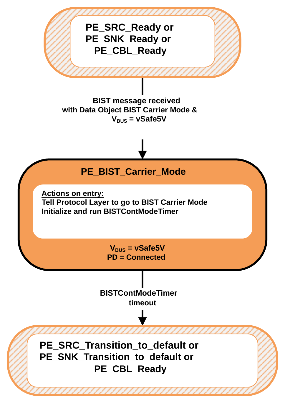
9.2.26.4.1.1. PE_BIST_Carrier_Mode State
The Source, Sink or Cable Plug Shall enter the PE_BIST_Carrier_Mode State from either the PE_SRC_Ready, PE_SNK_Ready or PE_CBL_Ready State when:
- A
BIST Messageis received with a BIST Carrier Mode BIST Data Object and - VBUS is at
vSafe5V.
On entry to the PE_BIST_Carrier_Mode State the Policy Engine Shall tell the Protocol Layer to go to BIST Carrier Mode (see Section 5.4.1) and Shall initialize and run the BISTContModeTimer.
The Policy Engine Shall transition to either the PE_SRC_Transition_to_default State, PE_SNK_Transition_to_default State or PE_CBL_Ready State (as appropriate) when:
- The BISTContModeTimer times out.
9.2.26.4.2. BIST Test Data Mode State Diagram
Figure 9.101 shows the State diagram required by a UUT, which can be either a Source, Sink, or Cable Plug, when operating in BIST Test Data Mode. Transitions Shall be from either the PE_SRC_Ready, PE_SNK_Ready or PE_CBL_Ready states.
Figure 9.101. BIST Test Data Mode State Diagram
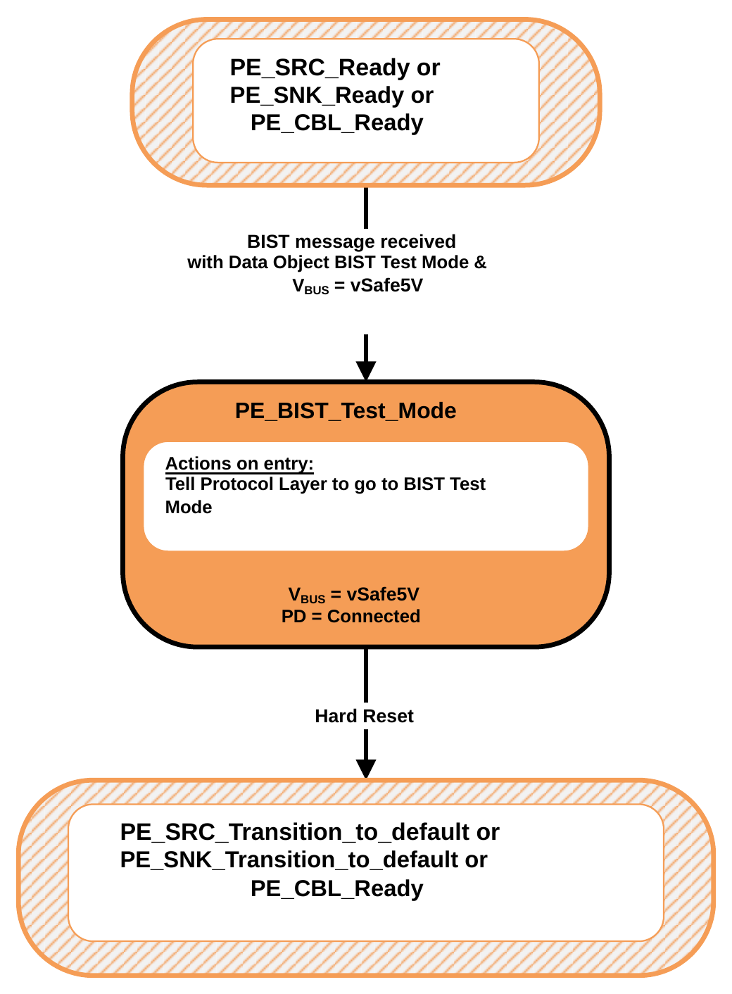
9.2.26.4.2.1. PE_BIST_Test_Mode State
The Source, Sink or Cable Plug Shall enter the PE_BIST_Test_Mode State from either the PE_SRC_Ready, PE_SNK_Ready or PE_CBL_Ready State when:
- A
BIST Messageis received with a BIST Test Data BIST Data Object and - VBUS is at
vSafe5V.
On entry to the PE_BIST_Test_Mode State the Policy Engine Shall tell the Protocol Layer to go into BIST Test Data Mode where it sends no further Messages except for GoodCRC Messages in response to received Messages (see Section 6.4.3).
The Policy Engine Shall transition to either the PE_SRC_Transition_to_default State, PE_SNK_Transition_to_default State or PE_CBL_Ready State (as appropriate) when:
- A Hard Reset occurs.
9.2.26.4.3. BIST Shared Capacity Test Mode State Diagram
Figure 9.102 shows the State diagram required by a UUT, which can be either a Source, Sink, or Cable Plug, when operating in BIST Shared Capacity Test Mode. Transitions Shall be from either the PE_SRC_Ready, PE_SNK_Ready or PE_CBL_Ready states.
Figure 9.102. BIST Shared Capacity Test Mode State Diagram
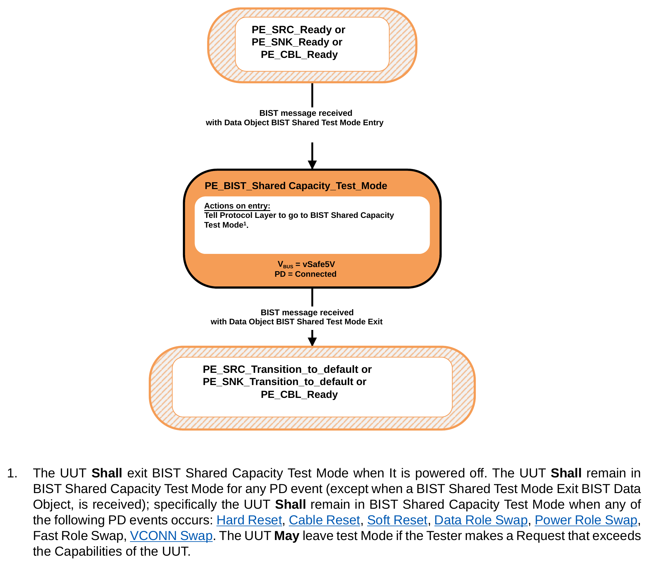
- The UUT Shall exit BIST Shared Capacity Test Mode when It is powered off. The UUT Shall remain in BIST Shared Capacity Test Mode for any PD event (except when a BIST Shared Test Mode Exit BIST Data Object, is received); specifically the UUT Shall remain in BIST Shared Capacity Test Mode when any of the following PD events occurs: Hard Reset, Cable Reset, Soft Reset, Data Role Swap, Power Role Swap, Fast Role Swap, VCONN Swap. The UUT May leave test Mode if the Tester makes a Request that exceeds the Capabilities of the UUT.
9.2.26.4.3.1. PE_BIST_Shared_Capacity_Test_Mode State
The Source, Sink or Cable Plug Shall enter the PE_BIST_Shared_Capacity_Test_Mode state when:
- A BIST Message is received with a BIST Shared Test Mode Entry BIST Data Object and
- VBUS is at vSafe5V.
On entry to the PE_BIST_Shared_Capacity_Test_Mode State the Policy Engine Shall tell the Protocol Layer to go to BIST Shared Capacity Test Mode (see Section 6.4.3).
The Policy Engine Shall transition to either the PE_SRC_Transition_to_default State, PE_SNK_Transition_to_default State or PE_CBL_Ready State (as appropriate) when:
- A BIST Message is received with a BIST Shared Test Mode Exit BIST Data Object.
9.2.26.5. USB Type-C Referenced States
This section contains states cross-referenced from the [USB-C] specification.
9.2.26.5.1. ErrorRecovery State
The ErrorRecovery State is used to electronically disconnect Port Partners using the USB Type-C connector. The ErrorRecovery State Shall be entered when there are errors on USB Type-C Ports which cannot be recovered by Hard Reset. The ErrorRecovery State Shall map to USB Type-C ErrorRecovery State operation as defined in the [USB-C] specification. Bus powered Sinks Shall Not be required to meet this requirement as removal of their power will serve the same purpose.
On entry to the ErrorRecovery State the Explicit Contract and PD Connection Shall be ended.
On exit from the ErrorRecovery State a new Explicit Contract Should be established once the Port Partners have re-Connected over the CC wire.